Network Communication Report: Two Router and Four Device Network

Verified

Added on  2021/06/14

|9
|1437
|286
Report
AI Summary
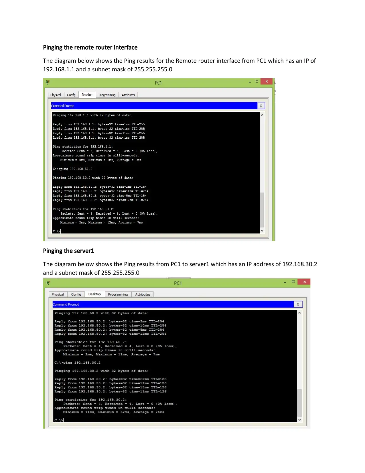
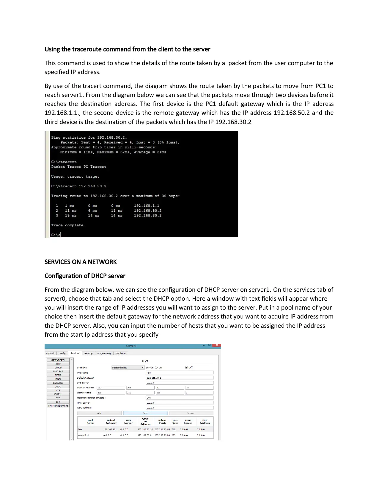
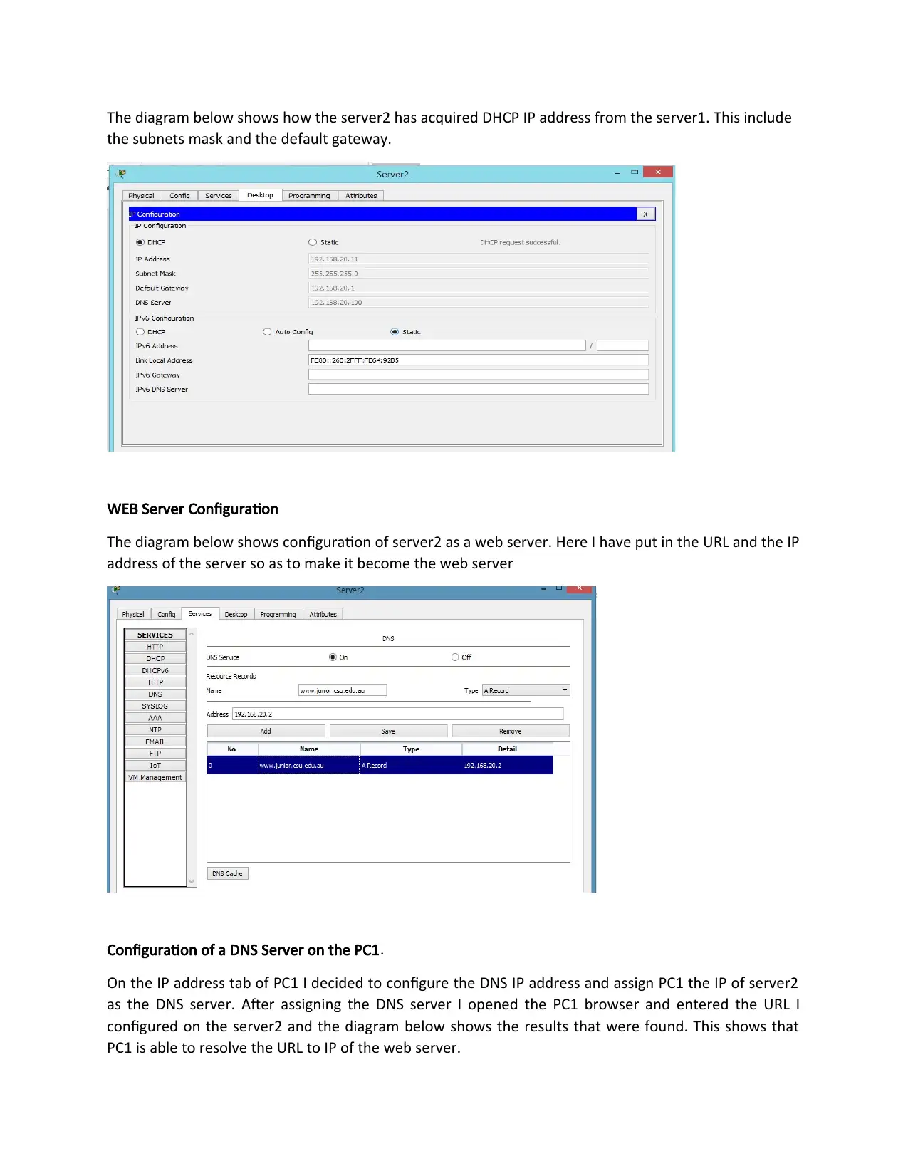
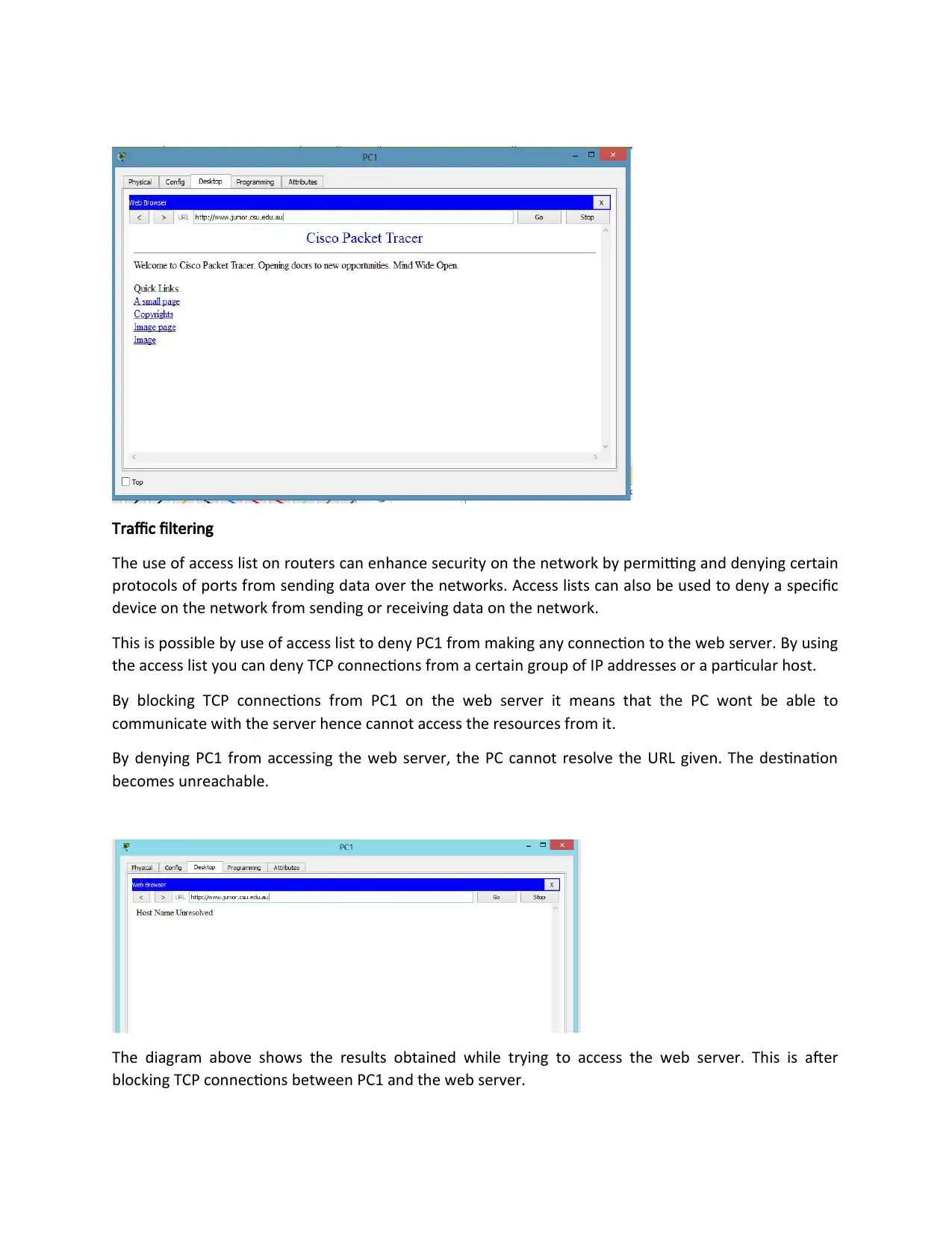
This report details the configuration and communication within a small network comprising two routers, two servers, and two PCs. The author assigned private IP addresses, configured router interfaces, and established routing protocols to enable packet transmission between all devices. The report showcases DHCP server configuration, allowing devices to automatically acquire IP addresses. Furthermore, it demonstrates the setup of a web server, enabling client access to web services. The report includes network topology diagrams, IP address assignments, routing configurations, and ping test results to illustrate the functionality of the network. The use of traceroute commands to track packet routes and the application of access lists for traffic filtering are also discussed, enhancing network security by controlling data flow and restricting access to web server resources. The report concludes with references to relevant networking literature.
Document Page
EXECUTIVE SUMMARY
The purpose of this report is to demonstrate how devices can communicate with each other over a
network. This report covers the routing and communication between devices on a small network setting.
The report analyzez and shows how two routers can communicate with each other and send
information to devices on the network. In my report I decided to demonstrate the network by use of
two routers and four end devices. That is two servers and two PCs. I assigned a private IP address to all
the devices in the network and after that I configured the interfaces on the routers. After I configured
the routing between the two routers so that all the devices in the network can send packets to each
other.
In my report also, I demonstrated how a DHCP server can be configured and how devices can acquire IP
addresses through the DHCP server. I also configured a web server so that a client machine can access
the service on the network. Through configuration of the web server the client machine can access the
web service regardless of anywhere he is but should be connected to the same network. The following
report will show the results that I got in details
tabler-icon-diamond-filled.svg

Secure Best Marks with AI Grader

Need help grading? Try our AI Grader for instant feedback on your assignments.
Document Page
NETWORK TOPOLOGY AND CONFIGURATIONS
The above diagram illustrates the topology that I used to configure the network. As you can see I used
two routers and four end points i.e. two pcs and two servers. I decided to use the private IP address of
range 192.168.0.0-192.168.255.255. PC1 has an IP of 192.168.1.2 while PC2 has an IP of 192.168.0.2.
The two routers are connected via a serial cable. The network address between the two routers is
192.168.50.0. Server1 has an IP of 192.168.30.2 while server2 has an IP of 192.168.20.2. After assigning
all the devices an IP address I configured default gateways for the devices. The diagram below shows
clearly the device, its IP address, its default gateway and the subnet mask
Device IP address Default gateway Subnet mask
PC1 192.168.1.2 192.168.1.1 255.255.255.0
PC2 192.168.0.2 192.168.0.1 255.255.255.0
Server1 192.168.30.2 192.168.30.1 255.255.255.0
Server2 192.168.20.2 192.168.20.1 255.255.255.0
Document Page
Configuration of routing on the routers i.e. IP packet forwarding
Routing refers to the process of selecting a path or a route for the network traffic. Therefore, it can be
said that it’s the process of establishing the route by which packets can pass from the source to the
specified destination.
The figure above shows the route taken by packets from one end point device to another after
configuration of routing in the network. This route is shown after putting the command show IP route on
the routers. This is after configuration of routing between the two routers so that the PCs can
communicate with the servers.
To configure routing, we use the command “IP route <network address> <subnet mask> <next hop
address>”.
In my network I used the following command on router2 to route traffic to PC1. Since there are two
network addresses I route the packets for both the networks
IP route 192.168.1.0 255.255.255.0 192.168.50.1
To route traffic to PC2 I used
IP route 192.168.0.0 255.255.255.0 192.168.50.1
On router one I used the following commands to route to server1 and server two since there are two
network addresses
IP route 192.168.30.0 255.255.255.0 192.168.50.2
To route traffic to server2
IP route 192.168.20.0 255.255.255.0 192.168.50.2
Document Page
Pinging the clients own interface.
The diagram below shows the results after I pinged PC1 IP address. The IP address of PC1 is 192.168.1.2
and the subnet mask is 255.255.255.0
Pinging the local router interface
The diagram below shows the ping results from PC1 to the local router gateway interface which has an
Ip address of 192.168.1.1 and the subnet mask is 255.255.255.0
tabler-icon-diamond-filled.svg

Secure Best Marks with AI Grader

Need help grading? Try our AI Grader for instant feedback on your assignments.
Document Page
Pinging the remote router interface
The diagram below shows the Ping results for the Remote router interface from PC1 which has an IP of
192.168.1.1 and a subnet mask of 255.255.255.0
Pinging the server1
The diagram below shows the Ping results from PC1 to server1 which has an IP address of 192.168.30.2
and a subnet mask of 255.255.255.0
Document Page
Using the traceroute command from the client to the server
This command is used to show the details of the route taken by a packet from the user computer to the
specified IP address.
By use of the tracert command, the diagram shows the route taken by the packets to move from PC1 to
reach server1. From the diagram below we can see that the packets move through two devices before it
reaches the destination address. The first device is the PC1 default gateway which is the IP address
192.168.1.1., the second device is the remote gateway which has the IP address 192.168.50.2 and the
third device is the destination of the packets which has the IP 192.168.30.2
SERVICES ON A NETWORK
Configuration of DHCP server
From the diagram below, we can see the configuration of DHCP server on server1. On the services tab of
server0, choose that tab and select the DHCP option. Here a window with text fields will appear where
you will insert the range of IP addresses you will want to assign to the server. Put in a pool name of your
choice then insert the default gateway for the network address that you want to acquire IP address from
the DHCP server. Also, you can input the number of hosts that you want to be assigned the IP address
from the start Ip address that you specify
Document Page
The diagram below shows how the server2 has acquired DHCP IP address from the server1. This include
the subnets mask and the default gateway.
WEB Server Configuration
The diagram below shows configuration of server2 as a web server. Here I have put in the URL and the IP
address of the server so as to make it become the web server
Configuration of a DNS Server on the PC1.
On the IP address tab of PC1 I decided to configure the DNS IP address and assign PC1 the IP of server2
as the DNS server. After assigning the DNS server I opened the PC1 browser and entered the URL I
configured on the server2 and the diagram below shows the results that were found. This shows that
PC1 is able to resolve the URL to IP of the web server.
tabler-icon-diamond-filled.svg

Paraphrase This Document

Need a fresh take? Get an instant paraphrase of this document with our AI Paraphraser
Document Page
Traffic filtering
The use of access list on routers can enhance security on the network by permitting and denying certain
protocols of ports from sending data over the networks. Access lists can also be used to deny a specific
device on the network from sending or receiving data on the network.
This is possible by use of access list to deny PC1 from making any connection to the web server. By using
the access list you can deny TCP connections from a certain group of IP addresses or a particular host.
By blocking TCP connections from PC1 on the web server it means that the PC wont be able to
communicate with the server hence cannot access the resources from it.
By denying PC1 from accessing the web server, the PC cannot resolve the URL given. The destination
becomes unreachable.
The diagram above shows the results obtained while trying to access the web server. This is after
blocking TCP connections between PC1 and the web server.
Document Page
REFERENCES
Jeff Doyle & Jennifer Carroll (2005). CCIE Professional Development: Routing TCP/IP Volume I, Second
Edition. ciscopress.com. p. 169.
ISBN 9781587052026.
Jeff Doyle & Jennifer Carroll (2005). CCIE Professional Development: Routing TCP/IP Volume I, Second
Edition. ciscopress.com. p. 170. ISBN 9781587052026.
Jeff Doyle & Jennifer Carroll (2005). CCIE Professional Development: Routing TCP/IP Volume I, Second
Edition. ciscopress.com. p. 170. ISBN 9781587052026.
Jeff Doyle & Jennifer Carroll (2005). CCIE Professional Development: Routing TCP/IP Volume I, Second
Edition. ciscopress.com. p. 170. ISBN 9781587052026.
Jeff Doyle & Jennifer Carroll (2005). CCIE Professional Development: Routing TCP/IP Volume I, Second
Edition. ciscopress.com. p. 170. ISBN 9781587052026.
chevron_up_icon
1 out of 9
circle_padding
hide_on_mobile
zoom_out_icon
[object Object]