Configuration of Network Devices, Redundancy and Routing Protocols
VerifiedAdded on 2023/04/26
|20
|3031
|253
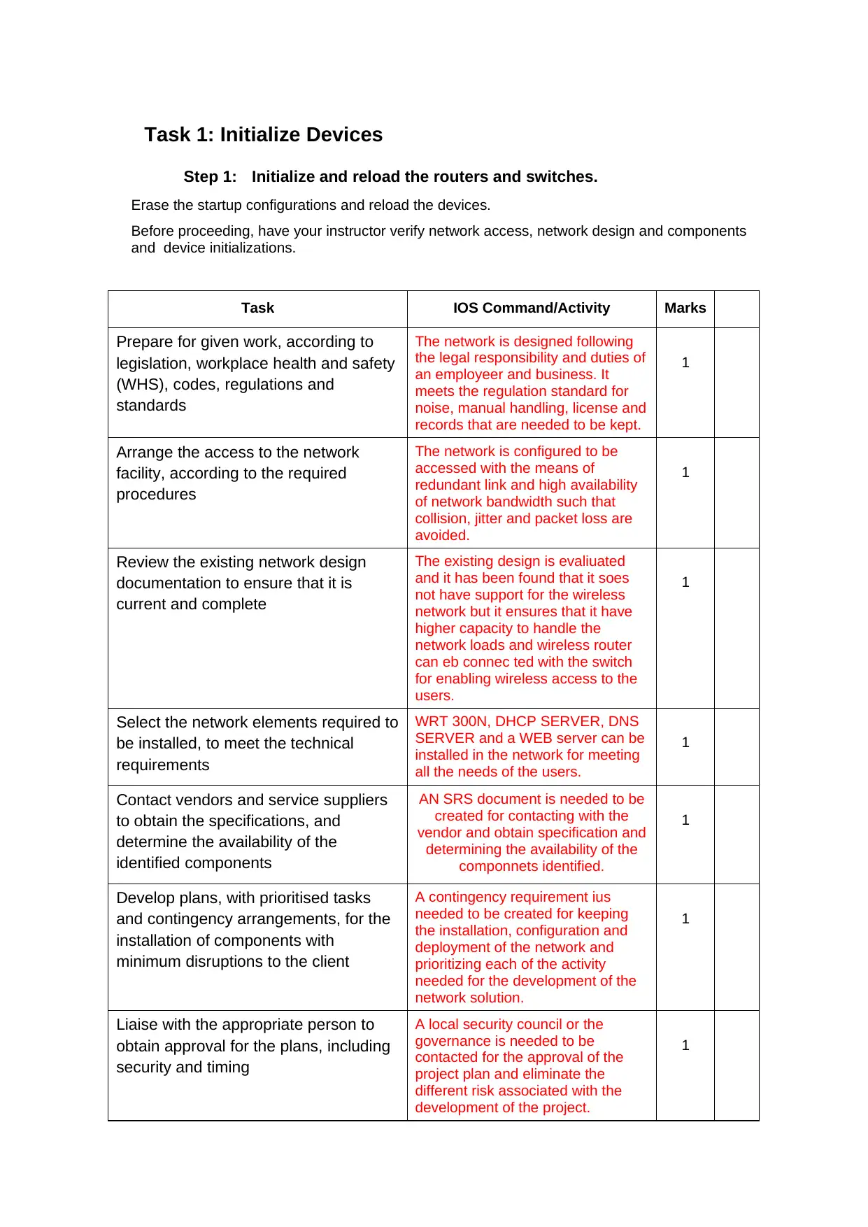
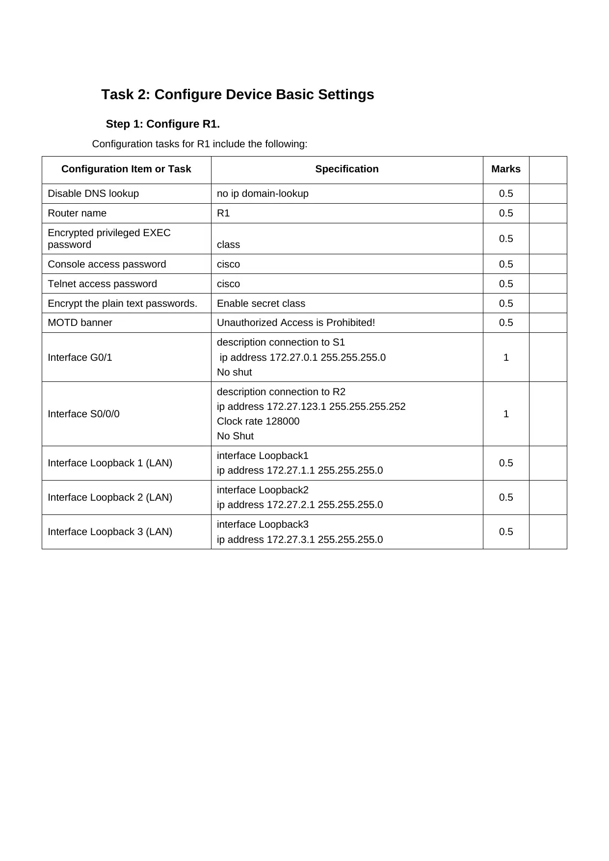
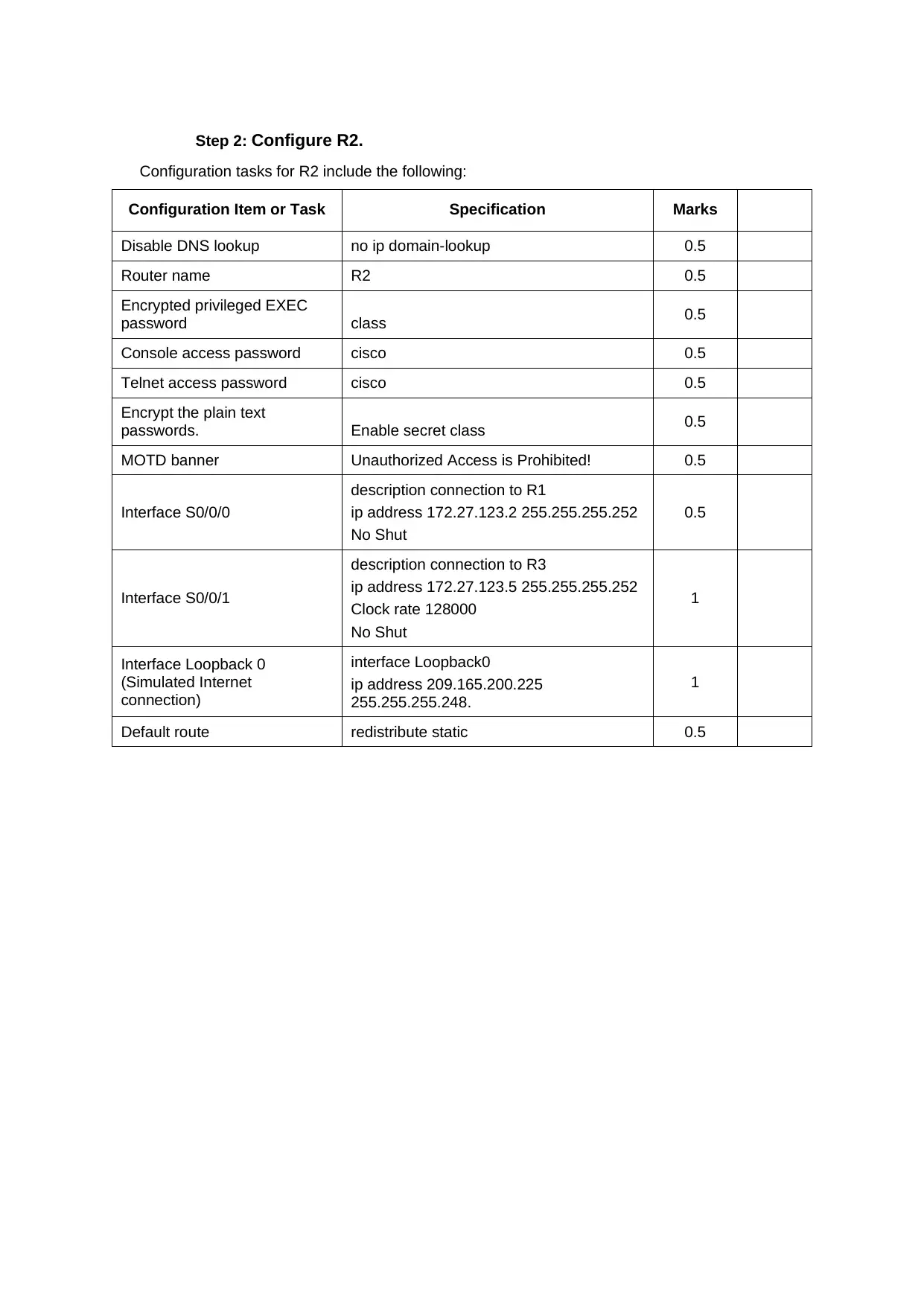
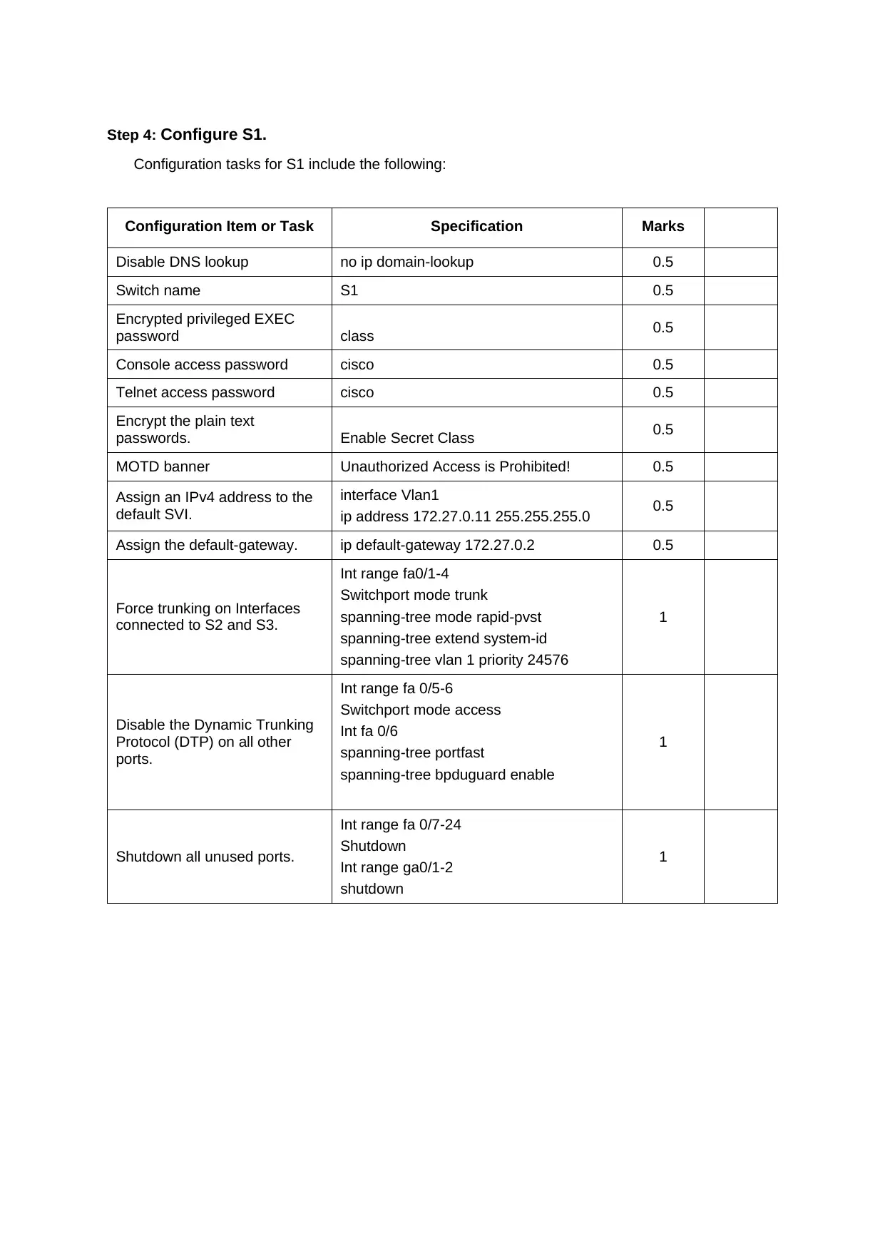
Practical Assignment
AI Summary
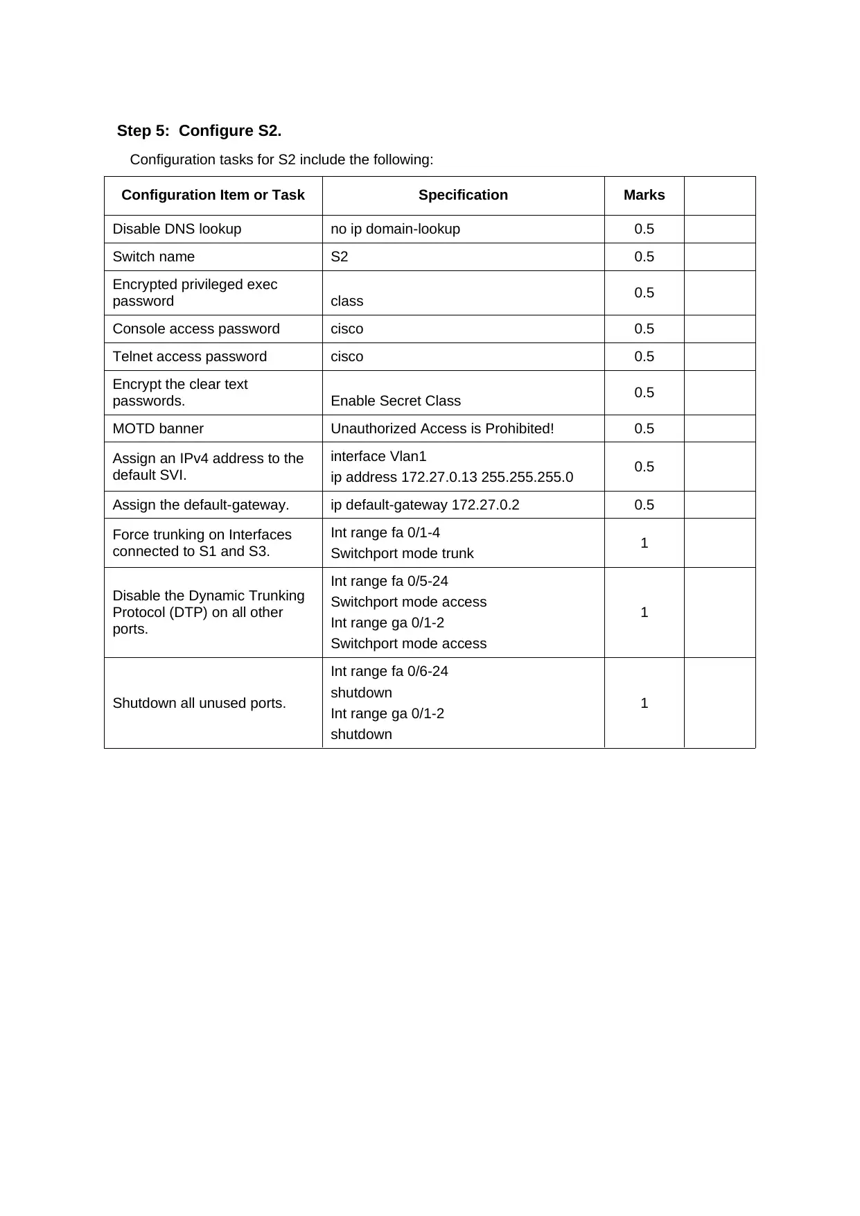
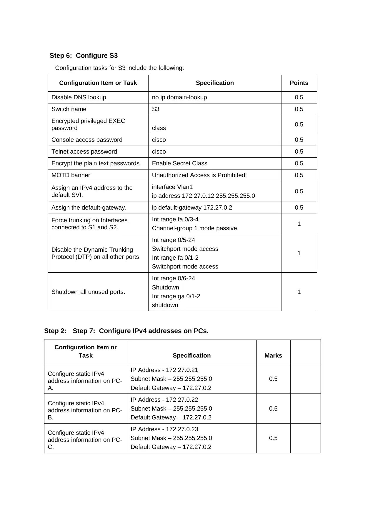
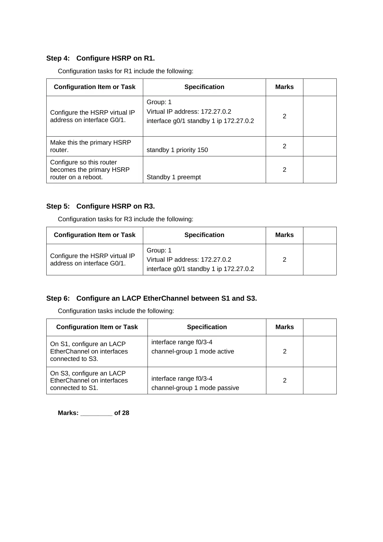
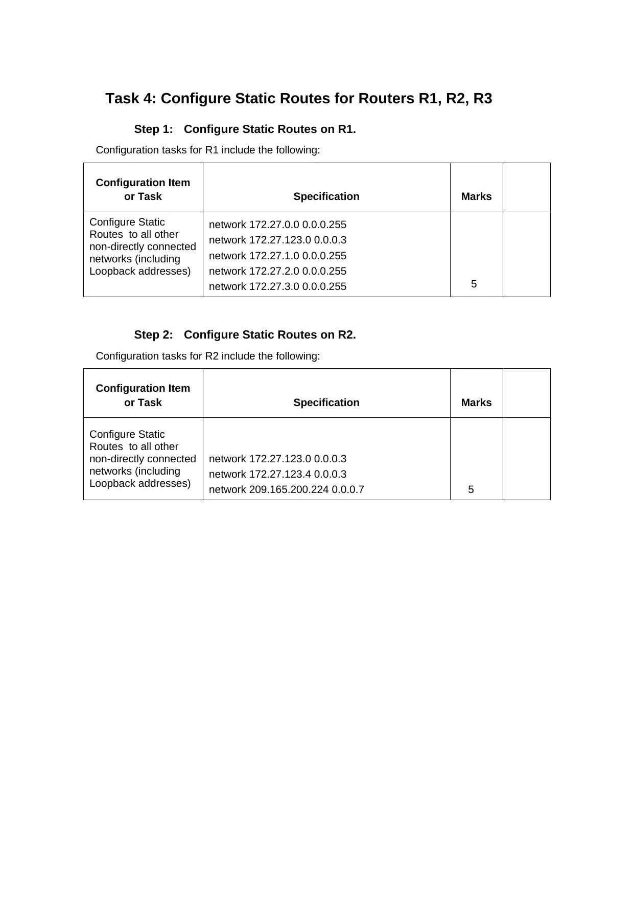
This practical assignment focuses on configuring network devices, implementing redundancy, and setting up routing protocols. The tasks include initializing routers and switches, configuring basic device settings such as disabling DNS lookup, setting router and switch names, encrypting passwords, and configuring interface descriptions and IP addresses. It covers configuring spanning tree protocol (STP) for LAN redundancy, HSRP for virtual IP addresses, and LACP EtherChannel for link aggregation. Additionally, the assignment involves configuring static routes and implementing EIGRP dynamic routing protocol by advertising connected networks, setting passive interfaces, disabling auto summarization, and configuring MD5 authentication. The solution provides specific commands and configurations for routers (R1, R2, R3) and switches (S1, S2, S3), as well as IPv4 address configurations for PCs.

Task 1: Initialize Devices
Step 1: Initialize and reload the routers and switches.
Erase the startup configurations and reload the devices.
Before proceeding, have your instructor verify network access, network design and components
and device initializations.
Task IOS Command/Activity Marks
Prepare for given work, according to
legislation, workplace health and safety
(WHS), codes, regulations and
standards
The network is designed following
the legal responsibility and duties of
an employeer and business. It
meets the regulation standard for
noise, manual handling, license and
records that are needed to be kept.
1
Arrange the access to the network
facility, according to the required
procedures
The network is configured to be
accessed with the means of
redundant link and high availability
of network bandwidth such that
collision, jitter and packet loss are
avoided.
1
Review the existing network design
documentation to ensure that it is
current and complete
The existing design is evaliuated
and it has been found that it soes
not have support for the wireless
network but it ensures that it have
higher capacity to handle the
network loads and wireless router
can eb connec ted with the switch
for enabling wireless access to the
users.
1
Select the network elements required to
be installed, to meet the technical
requirements
WRT 300N, DHCP SERVER, DNS
SERVER and a WEB server can be
installed in the network for meeting
all the needs of the users.
1
Contact vendors and service suppliers
to obtain the specifications, and
determine the availability of the
identified components
AN SRS document is needed to be
created for contacting with the
vendor and obtain specification and
determining the availability of the
componnets identified.
1
Develop plans, with prioritised tasks
and contingency arrangements, for the
installation of components with
minimum disruptions to the client
A contingency requirement ius
needed to be created for keeping
the installation, configuration and
deployment of the network and
prioritizing each of the activity
needed for the development of the
network solution.
1
Liaise with the appropriate person to
obtain approval for the plans, including
security and timing
A local security council or the
governance is needed to be
contacted for the approval of the
project plan and eliminate the
different risk associated with the
development of the project.
1
Paraphrase This Document
Need a fresh take? Get an instant paraphrase of this document with our AI Paraphraser

Erase the startup-config file on all routers. Erase startup-config 2
Reload all routers. reload 2
Erase the startup-config file on all switches
and remove the old VLAN database.
Erase start
Reload
Delete flash:vlan.dat
2
Reload all switches. reload 2
Verify VLAN database is absent from flash
on all switches.
Show vlan brief 2
Marks: __________ of 17
Reload all routers. reload 2
Erase the startup-config file on all switches
and remove the old VLAN database.
Erase start
Reload
Delete flash:vlan.dat
2
Reload all switches. reload 2
Verify VLAN database is absent from flash
on all switches.
Show vlan brief 2
Marks: __________ of 17

Task 2: Configure Device Basic Settings
Step 1: Configure R1.
Configuration tasks for R1 include the following:
Configuration Item or Task Specification Marks
Disable DNS lookup no ip domain-lookup 0.5
Router name R1 0.5
Encrypted privileged EXEC
password class 0.5
Console access password cisco 0.5
Telnet access password cisco 0.5
Encrypt the plain text passwords. Enable secret class 0.5
MOTD banner Unauthorized Access is Prohibited! 0.5
Interface G0/1
description connection to S1
ip address 172.27.0.1 255.255.255.0
No shut
1
Interface S0/0/0
description connection to R2
ip address 172.27.123.1 255.255.255.252
Clock rate 128000
No Shut
1
Interface Loopback 1 (LAN) interface Loopback1
ip address 172.27.1.1 255.255.255.0 0.5
Interface Loopback 2 (LAN) interface Loopback2
ip address 172.27.2.1 255.255.255.0 0.5
Interface Loopback 3 (LAN) interface Loopback3
ip address 172.27.3.1 255.255.255.0 0.5
⊘ This is a preview!⊘
Do you want full access?
Subscribe today to unlock all pages.

Trusted by 1+ million students worldwide

Step 2: Configure R2.
Configuration tasks for R2 include the following:
Configuration Item or Task Specification Marks
Disable DNS lookup no ip domain-lookup 0.5
Router name R2 0.5
Encrypted privileged EXEC
password class 0.5
Console access password cisco 0.5
Telnet access password cisco 0.5
Encrypt the plain text
passwords. Enable secret class 0.5
MOTD banner Unauthorized Access is Prohibited! 0.5
Interface S0/0/0
description connection to R1
ip address 172.27.123.2 255.255.255.252
No Shut
0.5
Interface S0/0/1
description connection to R3
ip address 172.27.123.5 255.255.255.252
Clock rate 128000
No Shut
1
Interface Loopback 0
(Simulated Internet
connection)
interface Loopback0
ip address 209.165.200.225
255.255.255.248.
1
Default route redistribute static 0.5
Paraphrase This Document
Need a fresh take? Get an instant paraphrase of this document with our AI Paraphraser

Step 3: Configure R3.
Configuration tasks for R3 include the following:
Configuration Item or Task Specification Marks
Disable DNS lookup no ip domain-lookup 0.5
Router name R3 0.5
Encrypted privileged EXEC
password class 0.5
Console access password cisco 0.5
Telnet access password cisco 0.5
Encrypt the plain text
passwords. Enable secret class 0.5
MOTD banner Unauthorized Access is Prohibited! 0.5
Interface G0/1
description connection to S3
ip address 172.27.0.3 255.255.255.0
No Shut
1
Interface S0/0/1
description connection to R2
bandwidth 128
ip address 172.27.123.6
255.255.255.252
No shut
1
Interface Loopback 4 (LAN) interface Loopback4
ip address 172.27.4.1 255.255.255.0 0.5
Interface Loopback 5 (LAN) interface Loopback5
ip address 172.27.5.1 255.255.255.0 0.5
Interface Loopback 6 (LAN) interface Loopback6
ip address 172.27.6.1 255.255.255.0 0.5

Step 4: Configure S1.
Configuration tasks for S1 include the following:
Configuration Item or Task Specification Marks
Disable DNS lookup no ip domain-lookup 0.5
Switch name S1 0.5
Encrypted privileged EXEC
password class 0.5
Console access password cisco 0.5
Telnet access password cisco 0.5
Encrypt the plain text
passwords. Enable Secret Class 0.5
MOTD banner Unauthorized Access is Prohibited! 0.5
Assign an IPv4 address to the
default SVI.
interface Vlan1
ip address 172.27.0.11 255.255.255.0 0.5
Assign the default-gateway. ip default-gateway 172.27.0.2 0.5
Force trunking on Interfaces
connected to S2 and S3.
Int range fa0/1-4
Switchport mode trunk
spanning-tree mode rapid-pvst
spanning-tree extend system-id
spanning-tree vlan 1 priority 24576
1
Disable the Dynamic Trunking
Protocol (DTP) on all other
ports.
Int range fa 0/5-6
Switchport mode access
Int fa 0/6
spanning-tree portfast
spanning-tree bpduguard enable
1
Shutdown all unused ports.
Int range fa 0/7-24
Shutdown
Int range ga0/1-2
shutdown
1
⊘ This is a preview!⊘
Do you want full access?
Subscribe today to unlock all pages.

Trusted by 1+ million students worldwide

Step 5: Configure S2.
Configuration tasks for S2 include the following:
Configuration Item or Task Specification Marks
Disable DNS lookup no ip domain-lookup 0.5
Switch name S2 0.5
Encrypted privileged exec
password class 0.5
Console access password cisco 0.5
Telnet access password cisco 0.5
Encrypt the clear text
passwords. Enable Secret Class 0.5
MOTD banner Unauthorized Access is Prohibited! 0.5
Assign an IPv4 address to the
default SVI.
interface Vlan1
ip address 172.27.0.13 255.255.255.0 0.5
Assign the default-gateway. ip default-gateway 172.27.0.2 0.5
Force trunking on Interfaces
connected to S1 and S3.
Int range fa 0/1-4
Switchport mode trunk 1
Disable the Dynamic Trunking
Protocol (DTP) on all other
ports.
Int range fa 0/5-24
Switchport mode access
Int range ga 0/1-2
Switchport mode access
1
Shutdown all unused ports.
Int range fa 0/6-24
shutdown
Int range ga 0/1-2
shutdown
1
Paraphrase This Document
Need a fresh take? Get an instant paraphrase of this document with our AI Paraphraser

Step 6: Configure S3
Configuration tasks for S3 include the following:
Configuration Item or Task Specification Points
Disable DNS lookup no ip domain-lookup 0.5
Switch name S3 0.5
Encrypted privileged EXEC
password class 0.5
Console access password cisco 0.5
Telnet access password cisco 0.5
Encrypt the plain text passwords. Enable Secret Class 0.5
MOTD banner Unauthorized Access is Prohibited! 0.5
Assign an IPv4 address to the
default SVI.
interface Vlan1
ip address 172.27.0.12 255.255.255.0 0.5
Assign the default-gateway. ip default-gateway 172.27.0.2 0.5
Force trunking on Interfaces
connected to S1 and S2.
Int range fa 0/3-4
Channel-group 1 mode passive 1
Disable the Dynamic Trunking
Protocol (DTP) on all other ports.
Int range 0/5-24
Switchport mode access
Int range fa 0/1-2
Switchport mode access
1
Shutdown all unused ports.
Int range 0/6-24
Shutdown
Int range ga 0/1-2
shutdown
1
Step 2: Step 7: Configure IPv4 addresses on PCs.
Configuration Item or
Task Specification Marks
Configure static IPv4
address information on PC-
A.
IP Address - 172.27.0.21
Subnet Mask – 255.255.255.0
Default Gateway – 172.27.0.2
0.5
Configure static IPv4
address information on PC-
B.
IP Address - 172.27.0.22
Subnet Mask – 255.255.255.0
Default Gateway – 172.27.0.2
0.5
Configure static IPv4
address information on PC-
C.
IP Address - 172.27.0.23
Subnet Mask – 255.255.255.0
Default Gateway – 172.27.0.2
0.5

Marks: _________ of 45
⊘ This is a preview!⊘
Do you want full access?
Subscribe today to unlock all pages.

Trusted by 1+ million students worldwide

Task 3: Configure LAN Redundancy and Link Aggregation
Step 1: Configure Spanning Tree on S1.
Configuration tasks for S1 include the following:
Configuration Item or Task Specification Marks
Configure Rapid PVST+. spanning-tree mode rapid-pvst 2
Configure as primary root
bridge for VLAN 1. spanning-tree vlan 1 priority 24576 2
Configure PortFast and BPDU
Guard on the interface
connected to PC-A.
interface FastEthernet0/6
switchport mode access
spanning-tree portfast
spanning-tree bpduguard enable
2
Step 2: Configure Spanning Tree on S2.
Configuration tasks for S2 include the following:
Configuration Item or Task Specification Marks
Configure Rapid PVST+. spanning-tree mode rapid-pvst 2
Configure PortFast and BPDU
Guard on the interface
connected to PC-B.
interface FastEthernet0/18
switchport mode access
spanning-tree portfast
spanning-tree bpduguard enable
2
Step 3: Configure Spanning Tree on S3.
Configuration tasks for S3 include the following:
Configuration Item or Task Specification Marks
Configure Rapid PVST+. spanning-tree mode rapid-pvst 2
Configure as secondary root
bridge for VLAN 1. spanning-tree vlan 1 priority 28672 2
Configure PortFast and BPDU
Guard on the interface
connected to PC-C.
interface FastEthernet0/18
switchport mode access
spanning-tree portfast
spanning-tree bpduguard enable
2
Paraphrase This Document
Need a fresh take? Get an instant paraphrase of this document with our AI Paraphraser

Step 4: Configure HSRP on R1.
Configuration tasks for R1 include the following:
Configuration Item or Task Specification Marks
Configure the HSRP virtual IP
address on interface G0/1.
Group: 1
Virtual IP address: 172.27.0.2
interface g0/1 standby 1 ip 172.27.0.2 2
Make this the primary HSRP
router. standby 1 priority 150 2
Configure so this router
becomes the primary HSRP
router on a reboot. Standby 1 preempt
2
Step 5: Configure HSRP on R3.
Configuration tasks for R3 include the following:
Configuration Item or Task Specification Marks
Configure the HSRP virtual IP
address on interface G0/1.
Group: 1
Virtual IP address: 172.27.0.2
interface g0/1 standby 1 ip 172.27.0.2
2
Step 6: Configure an LACP EtherChannel between S1 and S3.
Configuration tasks include the following:
Configuration Item or Task Specification Marks
On S1, configure an LACP
EtherChannel on interfaces
connected to S3.
interface range f0/3-4
channel-group 1 mode active 2
On S3, configure an LACP
EtherChannel on interfaces
connected to S1.
interface range f0/3-4
channel-group 1 mode passive
2
Marks: _________ of 28

Task 4: Configure Static Routes for Routers R1, R2, R3
Step 1: Configure Static Routes on R1.
Configuration tasks for R1 include the following:
Configuration Item
or Task Specification Marks
Configure Static
Routes to all other
non-directly connected
networks (including
Loopback addresses)
network 172.27.0.0 0.0.0.255
network 172.27.123.0 0.0.0.3
network 172.27.1.0 0.0.0.255
network 172.27.2.0 0.0.0.255
network 172.27.3.0 0.0.0.255 5
Step 2: Configure Static Routes on R2.
Configuration tasks for R2 include the following:
Configuration Item
or Task Specification Marks
Configure Static
Routes to all other
non-directly connected
networks (including
Loopback addresses)
network 172.27.123.0 0.0.0.3
network 172.27.123.4 0.0.0.3
network 209.165.200.224 0.0.0.7 5
⊘ This is a preview!⊘
Do you want full access?
Subscribe today to unlock all pages.

Trusted by 1+ million students worldwide
1 out of 20
Related Documents
Your All-in-One AI-Powered Toolkit for Academic Success.
+13062052269
info@desklib.com
Available 24*7 on WhatsApp / Email
Unlock your academic potential
Copyright © 2020–2025 A2Z Services. All Rights Reserved. Developed and managed by ZUCOL.


