Network Diagram: Subnetting, Router Configuration, and Ping Analysis

Verified

Added on  2020/05/11

|19
|813
|35
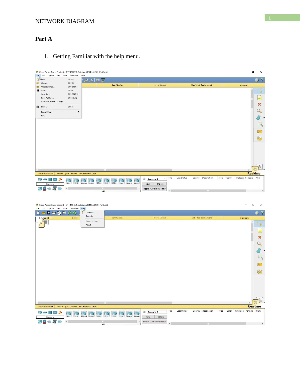
Practical Assignment
AI Summary
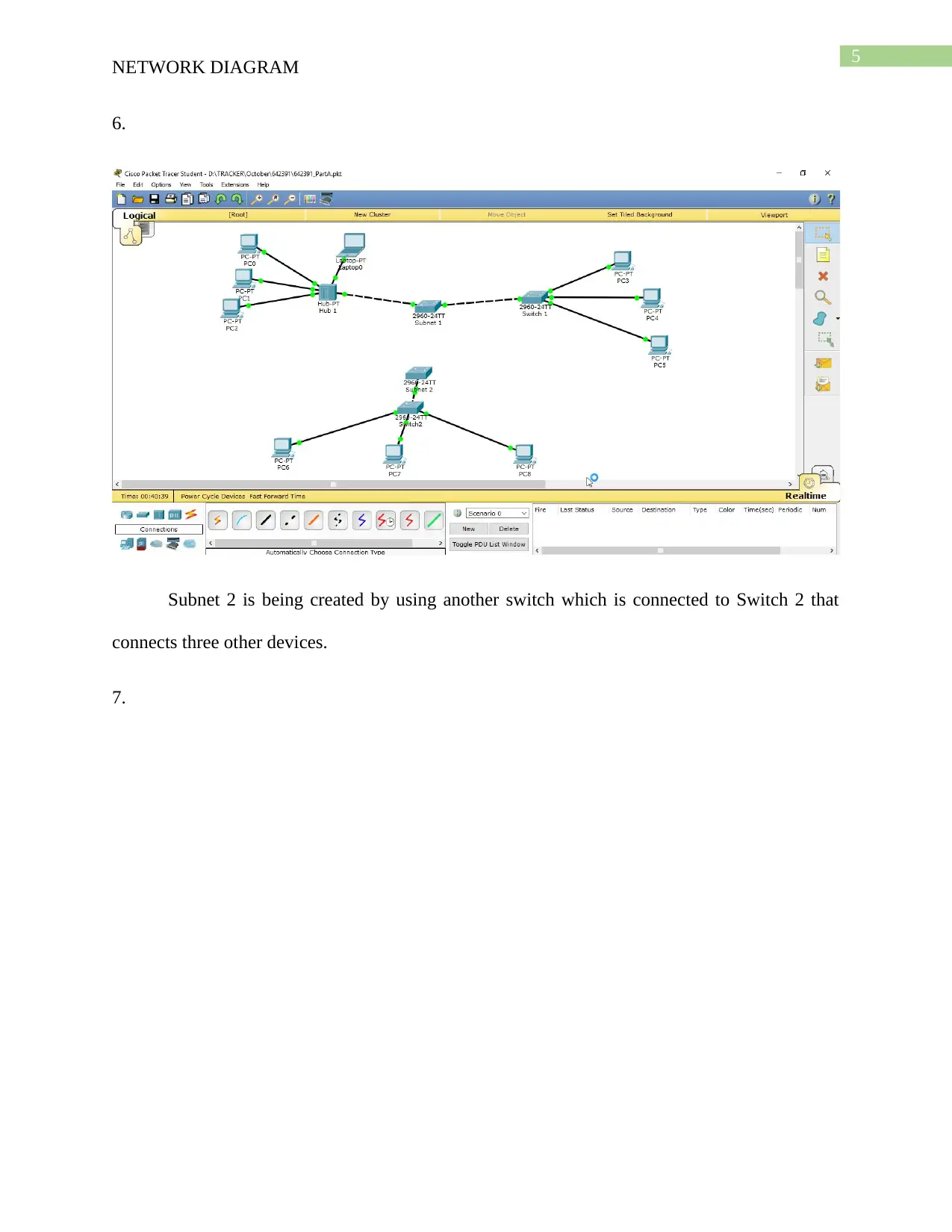
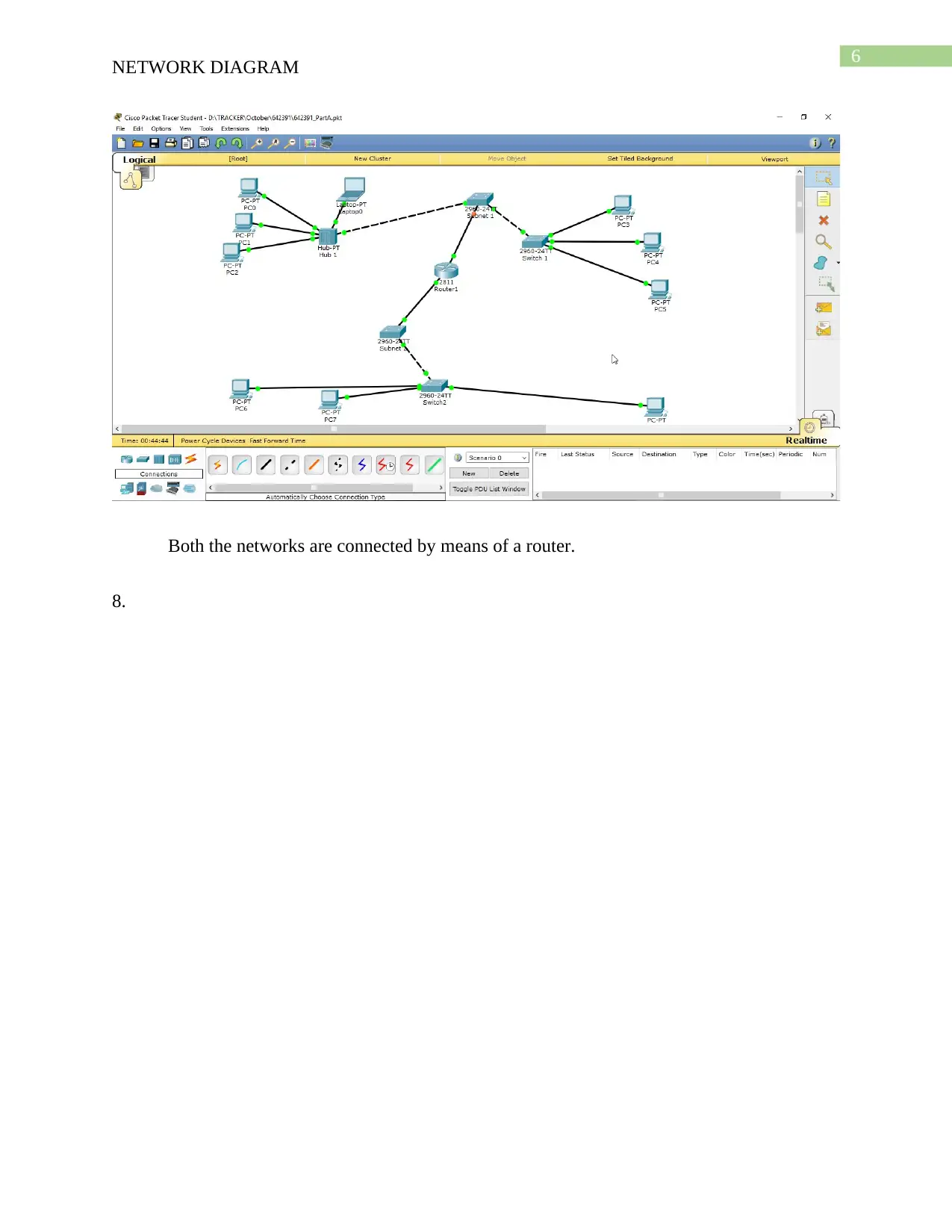
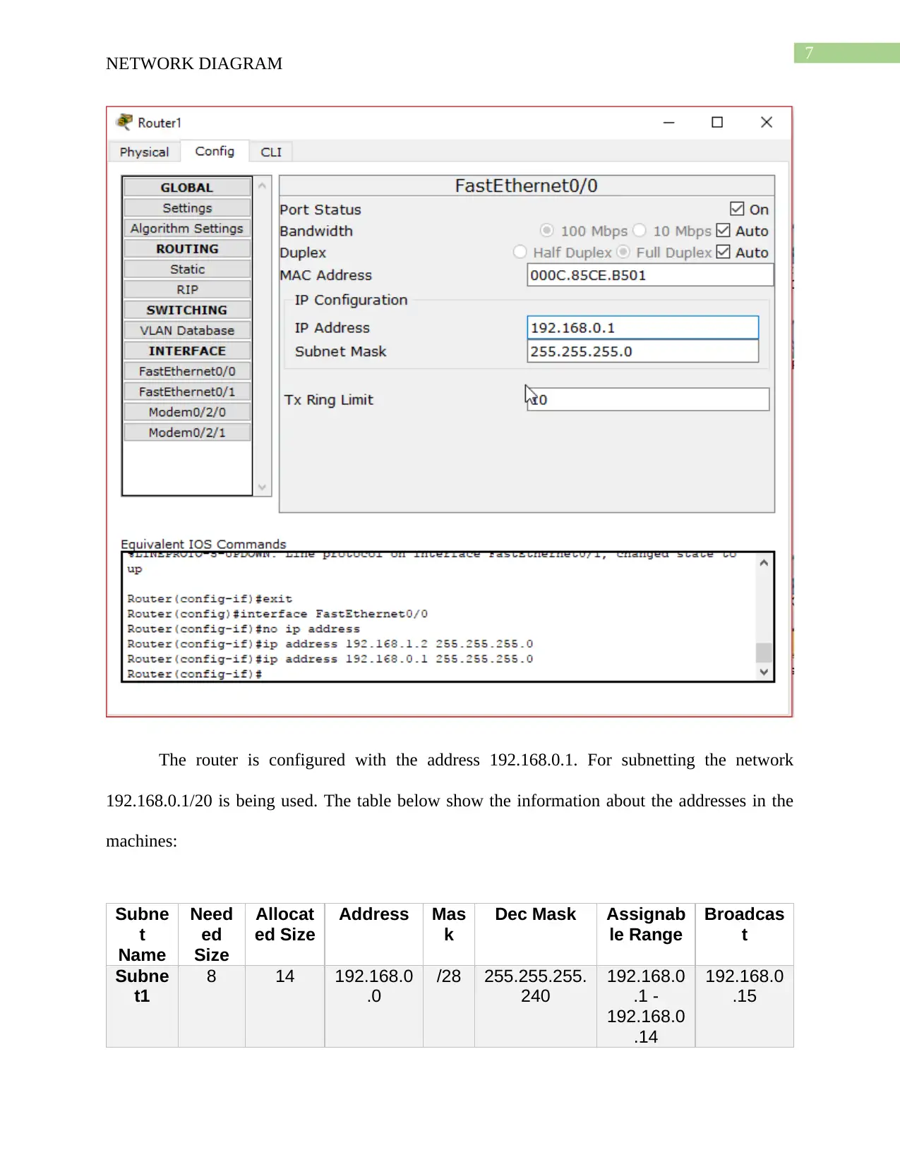
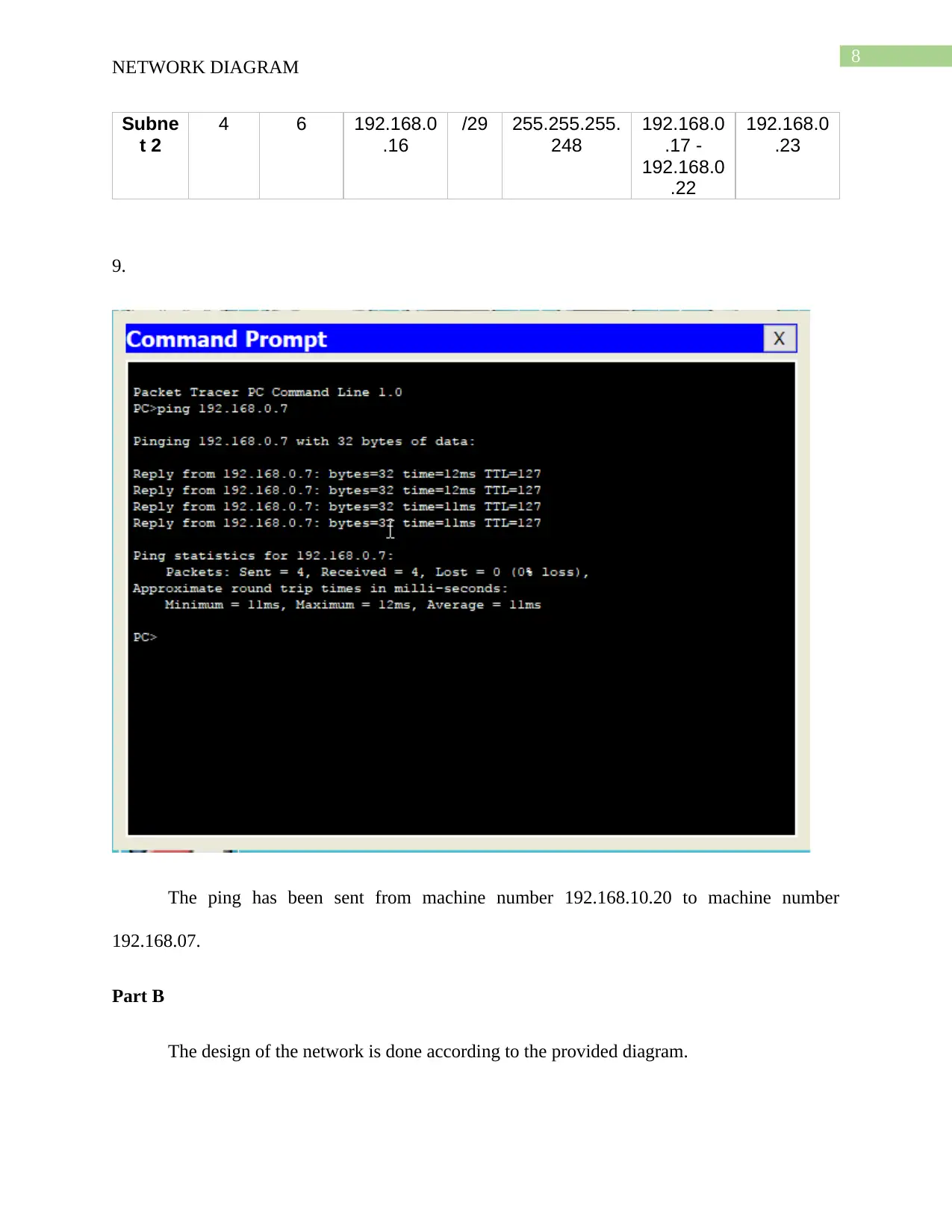
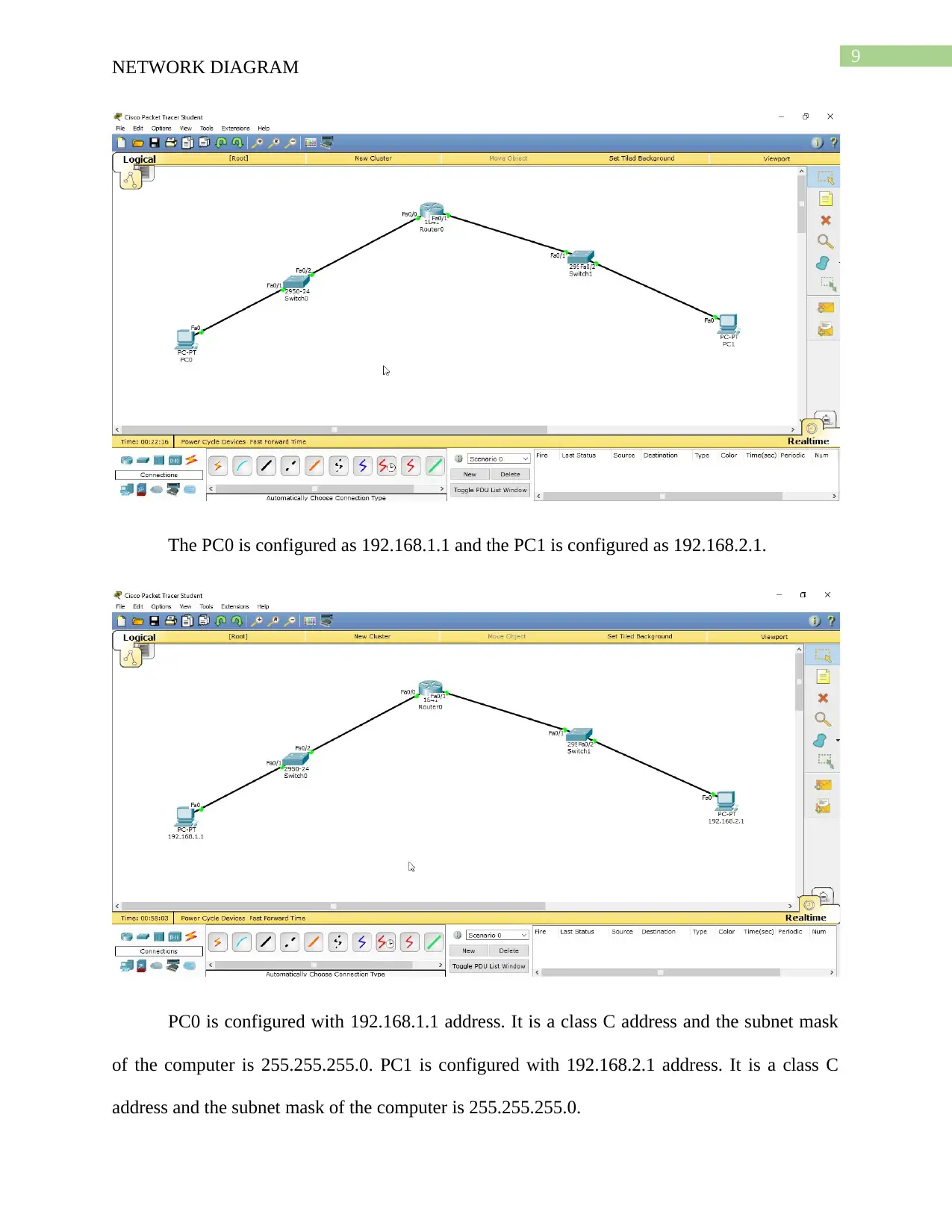
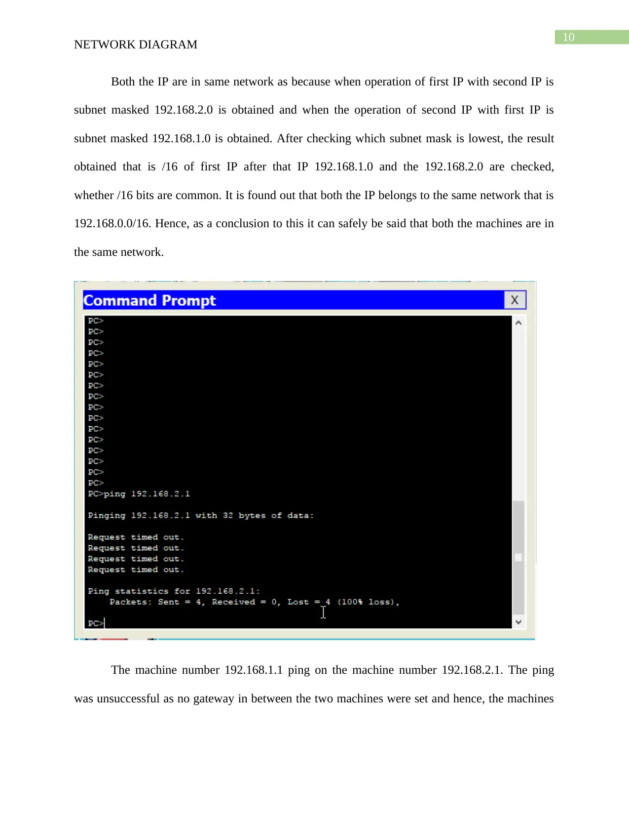
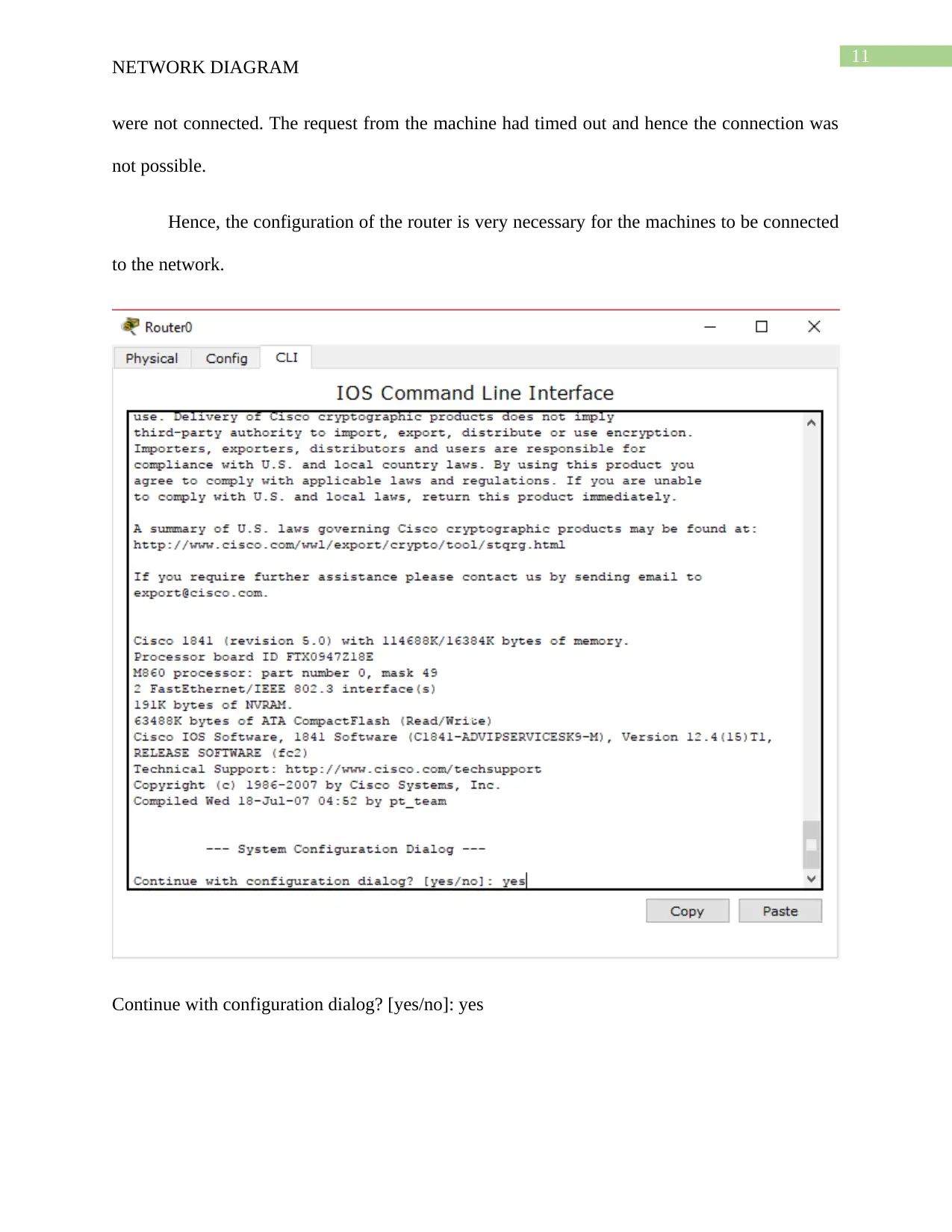
This assignment solution details the design and implementation of a network diagram using Cisco Packet Tracer. The student created two subnets connected by a router. Part A covers creating the network topology with nodes, hubs, switches, and Ethernet connections, along with IP addressing and subnetting configurations. The solution includes a table detailing subnet information and demonstrates ping tests between machines to verify connectivity. Part B focuses on configuring two PCs, assigning IP addresses, and analyzing network connectivity issues, including the need for router configuration to establish communication. The assignment also provides a bibliography of relevant sources used in the research and implementation of the network diagram, demonstrating the student's understanding of network design principles and practical application of networking concepts.
Document Page
Running head: NETWORK DIAGRAM
Network Diagram
Name of the Student:
Name of the University:
Author Note
tabler-icon-diamond-filled.svg

Paraphrase This Document

Need a fresh take? Get an instant paraphrase of this document with our AI Paraphraser
Document Page
1
NETWORK DIAGRAM
Part A
1. Getting Familiar with the help menu.
Document Page
2
NETWORK DIAGRAM
2.
Placing three node computers and a laptop in the work area
3.
Connection of the computers and the Laptops with the Hub named Hub 1.
Document Page
3
NETWORK DIAGRAM
The Ethernet connection is being used here. The hub is connected to the computers and
the laptop using the synchronous/ asynchronous ports. The copper straight through wires are
being used for the connection in between the hub and the nodes.
4.
Similar type of connections is implemented for switch 1 as well using PC3, PC4 and PC5.
tabler-icon-diamond-filled.svg

Paraphrase This Document

Need a fresh take? Get an instant paraphrase of this document with our AI Paraphraser
Document Page
4
NETWORK DIAGRAM
5.
Subnet 1 is created using a switch connecting Switch 1 and Hub 1. The use of the
simplest component has been done here.
Document Page
5
NETWORK DIAGRAM
6.
Subnet 2 is being created by using another switch which is connected to Switch 2 that
connects three other devices.
7.
Document Page
6
NETWORK DIAGRAM
Both the networks are connected by means of a router.
8.
tabler-icon-diamond-filled.svg

Paraphrase This Document

Need a fresh take? Get an instant paraphrase of this document with our AI Paraphraser
Document Page
7
NETWORK DIAGRAM
The router is configured with the address 192.168.0.1. For subnetting the network
192.168.0.1/20 is being used. The table below show the information about the addresses in the
machines:
Subne
t
Name
Need
ed
Size
Allocat
ed Size
Address Mas
k
Dec Mask Assignab
le Range
Broadcas
t
Subne
t1
8 14 192.168.0
.0
/28 255.255.255.
240
192.168.0
.1 -
192.168.0
.14
192.168.0
.15
Document Page
8
NETWORK DIAGRAM
Subne
t 2
4 6 192.168.0
.16
/29 255.255.255.
248
192.168.0
.17 -
192.168.0
.22
192.168.0
.23
9.
The ping has been sent from machine number 192.168.10.20 to machine number
192.168.07.
Part B
The design of the network is done according to the provided diagram.
Document Page
9
NETWORK DIAGRAM
The PC0 is configured as 192.168.1.1 and the PC1 is configured as 192.168.2.1.
PC0 is configured with 192.168.1.1 address. It is a class C address and the subnet mask
of the computer is 255.255.255.0. PC1 is configured with 192.168.2.1 address. It is a class C
address and the subnet mask of the computer is 255.255.255.0.
tabler-icon-diamond-filled.svg

Paraphrase This Document

Need a fresh take? Get an instant paraphrase of this document with our AI Paraphraser
Document Page
10
NETWORK DIAGRAM
Both the IP are in same network as because when operation of first IP with second IP is
subnet masked 192.168.2.0 is obtained and when the operation of second IP with first IP is
subnet masked 192.168.1.0 is obtained. After checking which subnet mask is lowest, the result
obtained that is /16 of first IP after that IP 192.168.1.0 and the 192.168.2.0 are checked,
whether /16 bits are common. It is found out that both the IP belongs to the same network that is
192.168.0.0/16. Hence, as a conclusion to this it can safely be said that both the machines are in
the same network.
The machine number 192.168.1.1 ping on the machine number 192.168.2.1. The ping
was unsuccessful as no gateway in between the two machines were set and hence, the machines
Document Page
11
NETWORK DIAGRAM
were not connected. The request from the machine had timed out and hence the connection was
not possible.
Hence, the configuration of the router is very necessary for the machines to be connected
to the network.
Continue with configuration dialog? [yes/no]: yes
Document Page
12
NETWORK DIAGRAM
The router was enabled
tabler-icon-diamond-filled.svg

Paraphrase This Document

Need a fresh take? Get an instant paraphrase of this document with our AI Paraphraser
Document Page
13
NETWORK DIAGRAM
The configuration is set for the router.
Document Page
14
NETWORK DIAGRAM
The configuration for the interface FastEthernet 0/1 is set up.
Document Page
15
NETWORK DIAGRAM
The state of the router is set to up.
tabler-icon-diamond-filled.svg

Paraphrase This Document

Need a fresh take? Get an instant paraphrase of this document with our AI Paraphraser
Document Page
16
NETWORK DIAGRAM
The configuration of the file is set up in the router.
Document Page
17
NETWORK DIAGRAM
After the router was set up the ping was successful from the machine 1 to machine 2.
Document Page
18
NETWORK DIAGRAM
Bibliography
Dangwal, K. and Kumar, V., 2014. Comparative study of eigrp and RIP using CISCO packet
tracer. International Journal of Engineering Sciences & Emerging Technologies, June 2014.
ISSN: 2231, 6604, pp.475-480.
Goyal, V. and Arora, G., 2017. Implementation of Enhanced Interior Gateway Routing Protocol
(EIGRP) in IPv6 Network. Research Journal of Advanced Engineering and Science, 2(1), pp.90-
95.
Javid, S.R., 2014. Role of Packet Tracer in learning Computer Networks. International Journal
of Advanced Research in Computer and Communication Engineering, 3(5), pp.6508-6511.
Prasad, N.H., Reddy, B.K., Amarnath, B. and Puthanial, M., 2016. Intervlan Routing and
Various Configurations on Vlan in a Network using Cisco Packet Tracer. International Journal
for Innovative Research in Science and Technology, 2(11), pp.749-758.
Wang, C. and CHEN, J., 2014, May. Implementation of GRE Over IPsec VPN Enterprise
Network Based on Cisco Packet Tracer. In 2014 2nd International Conference on Soft
Computing in Information Communication Technology (pp. 142-146). France: Atlantis Press.
chevron_up_icon
1 out of 19
circle_padding
hide_on_mobile
zoom_out_icon
[object Object]