SBM4104: Computer Network Design and Cloud Computing for ABC Company
VerifiedAdded on 2022/12/28
|20
|2687
|76
Report
AI Summary
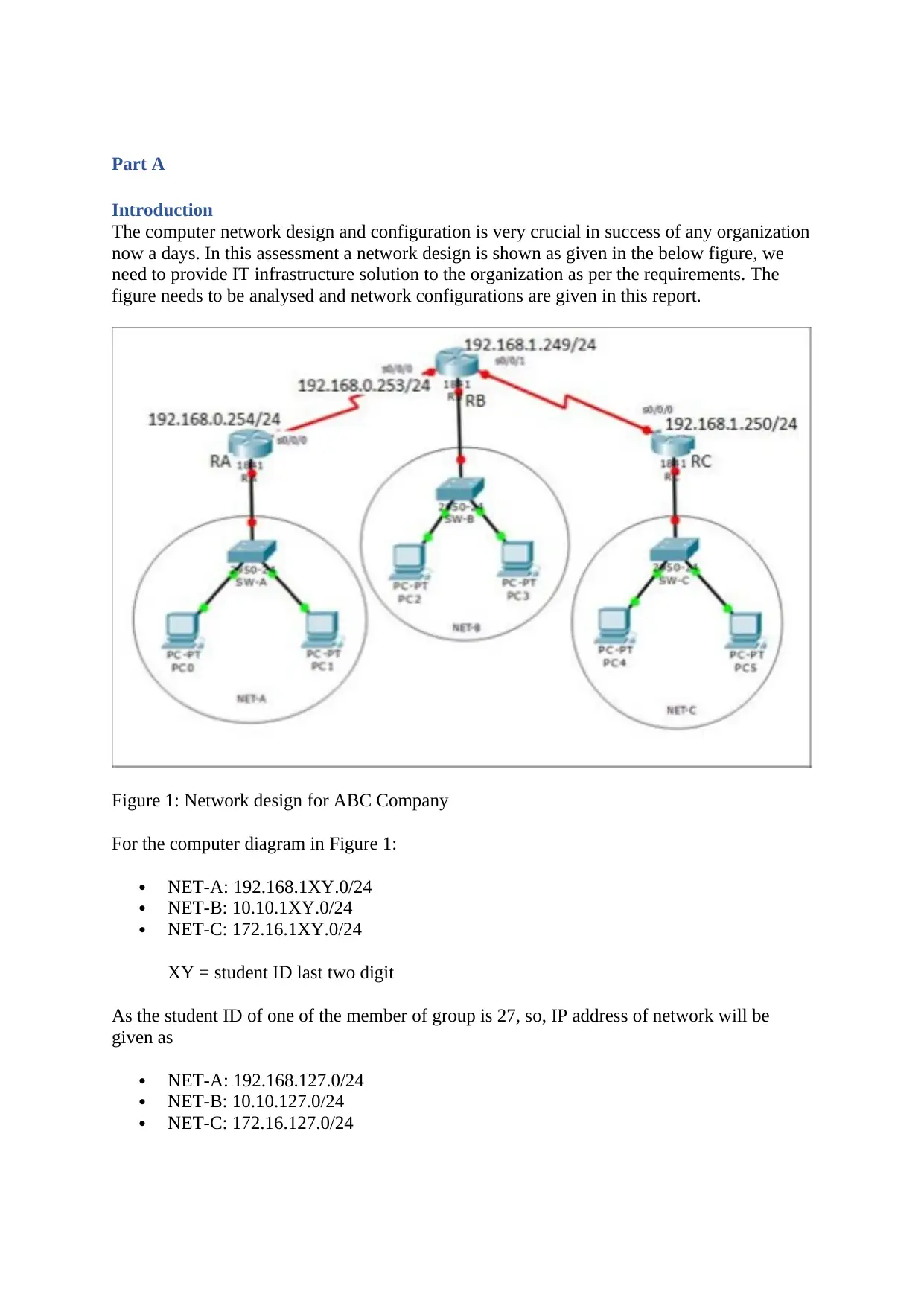
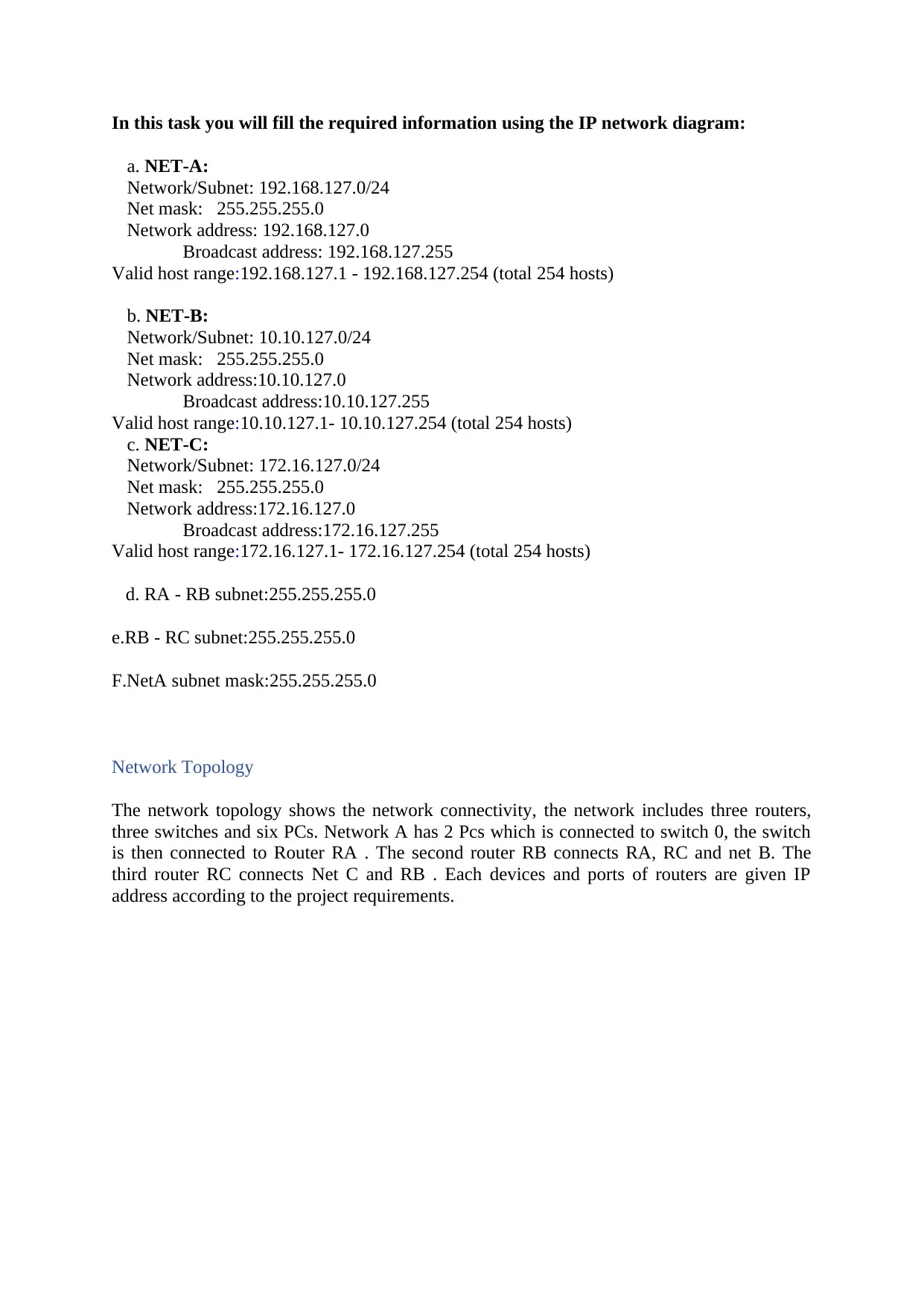
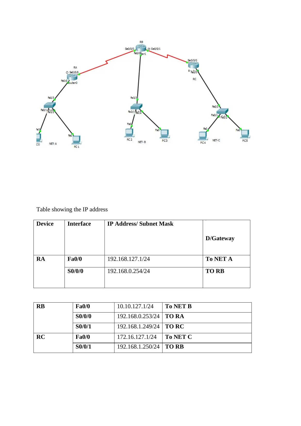
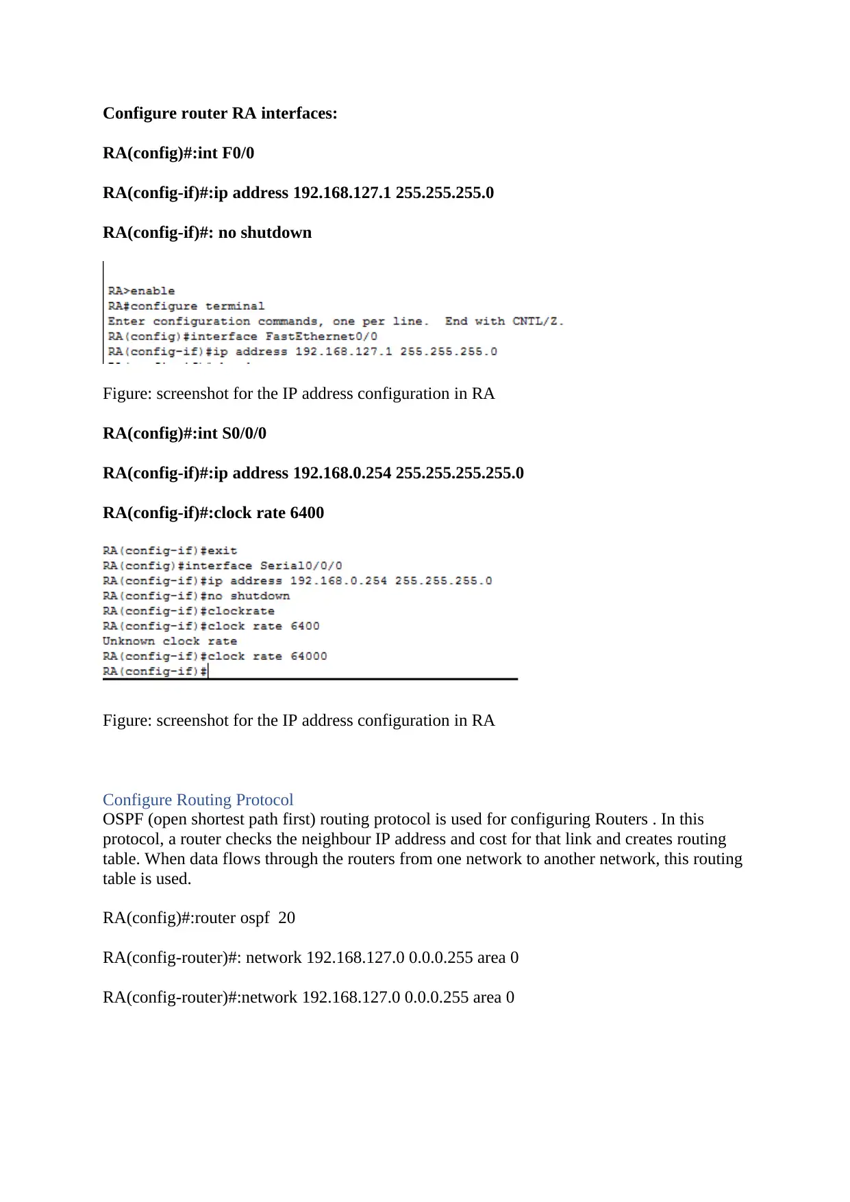
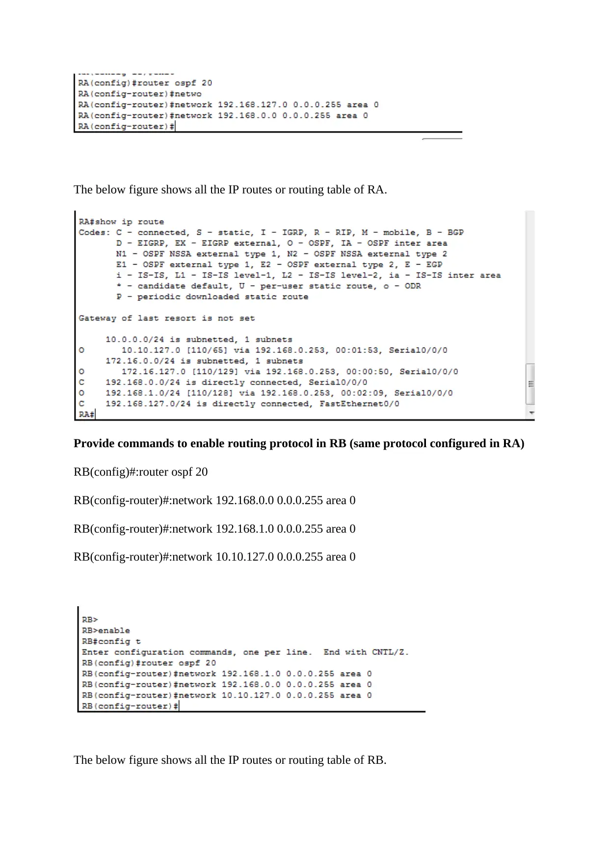
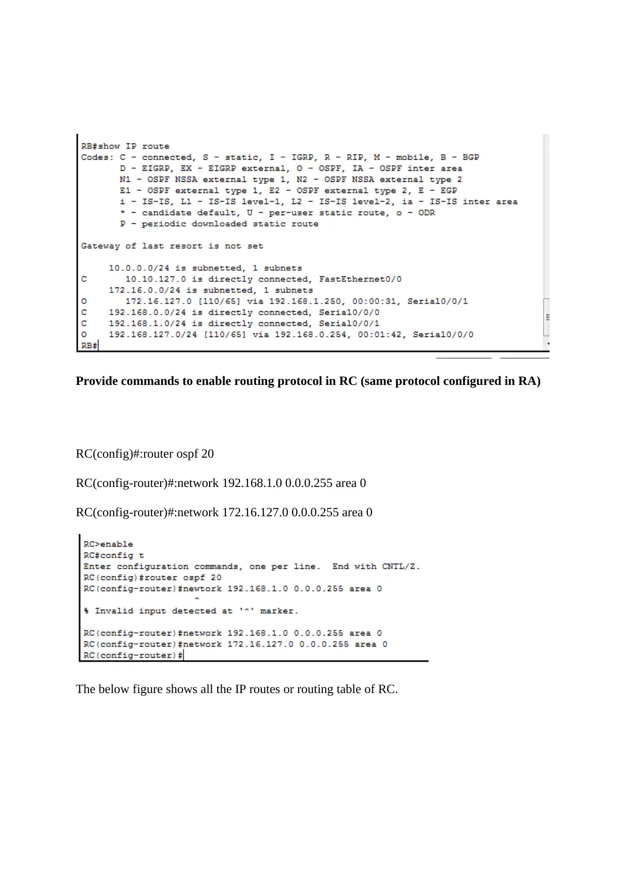
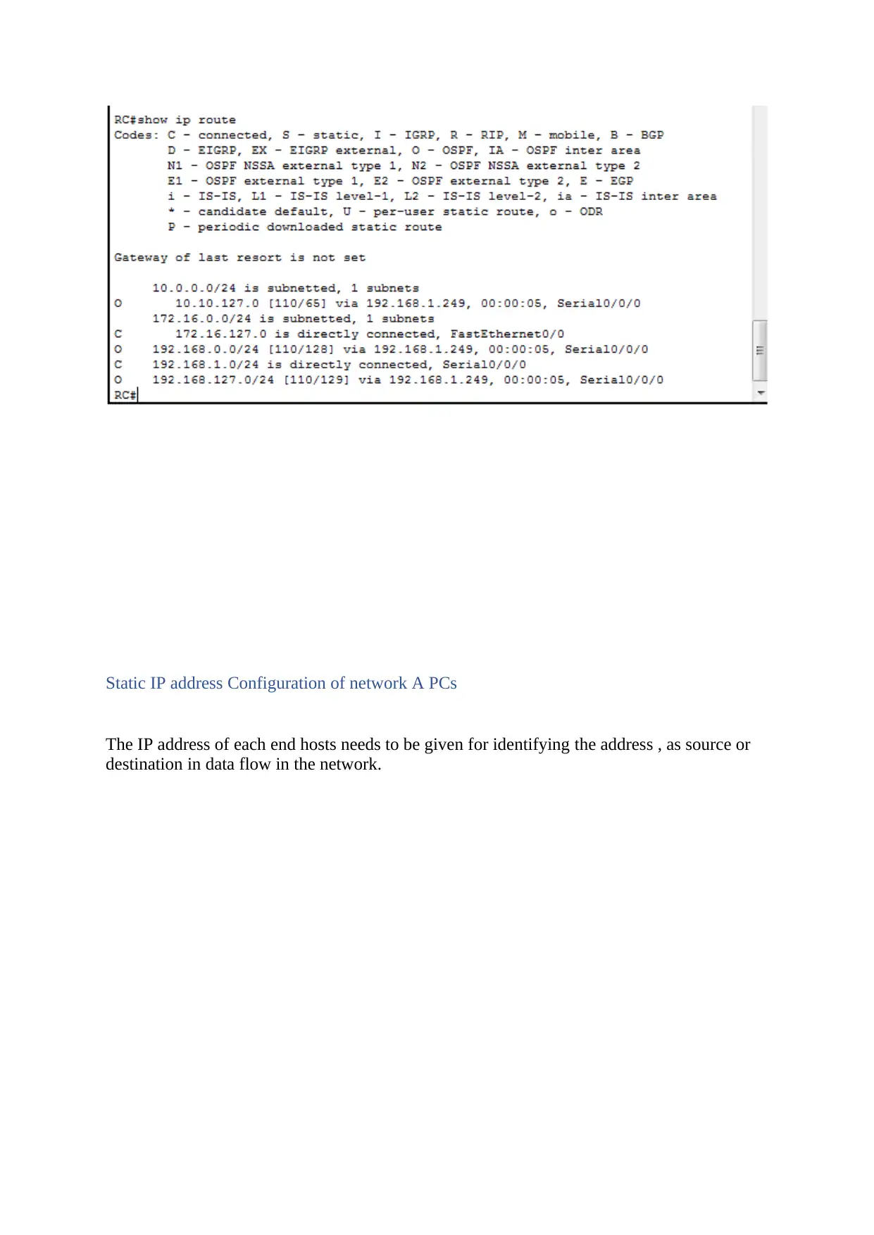
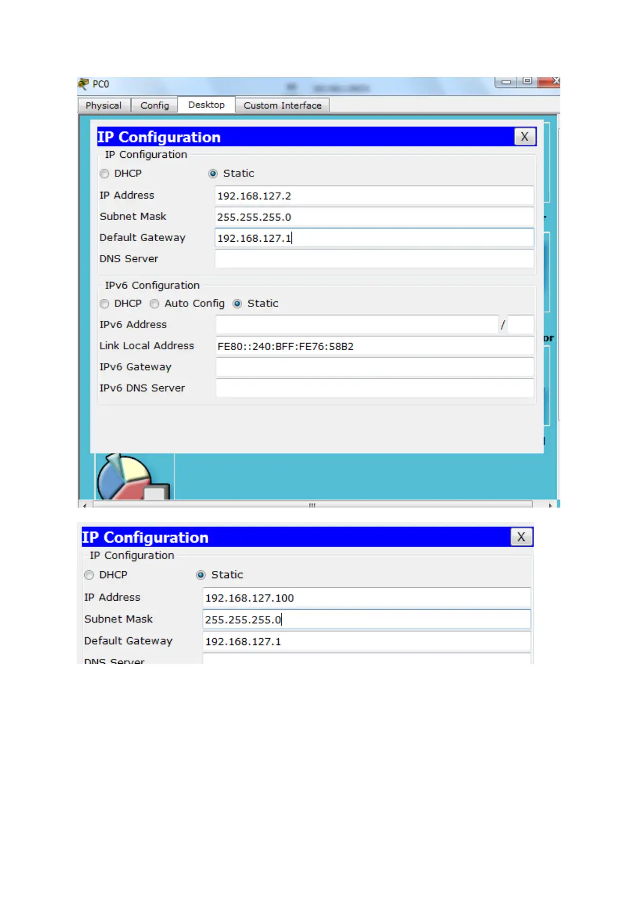
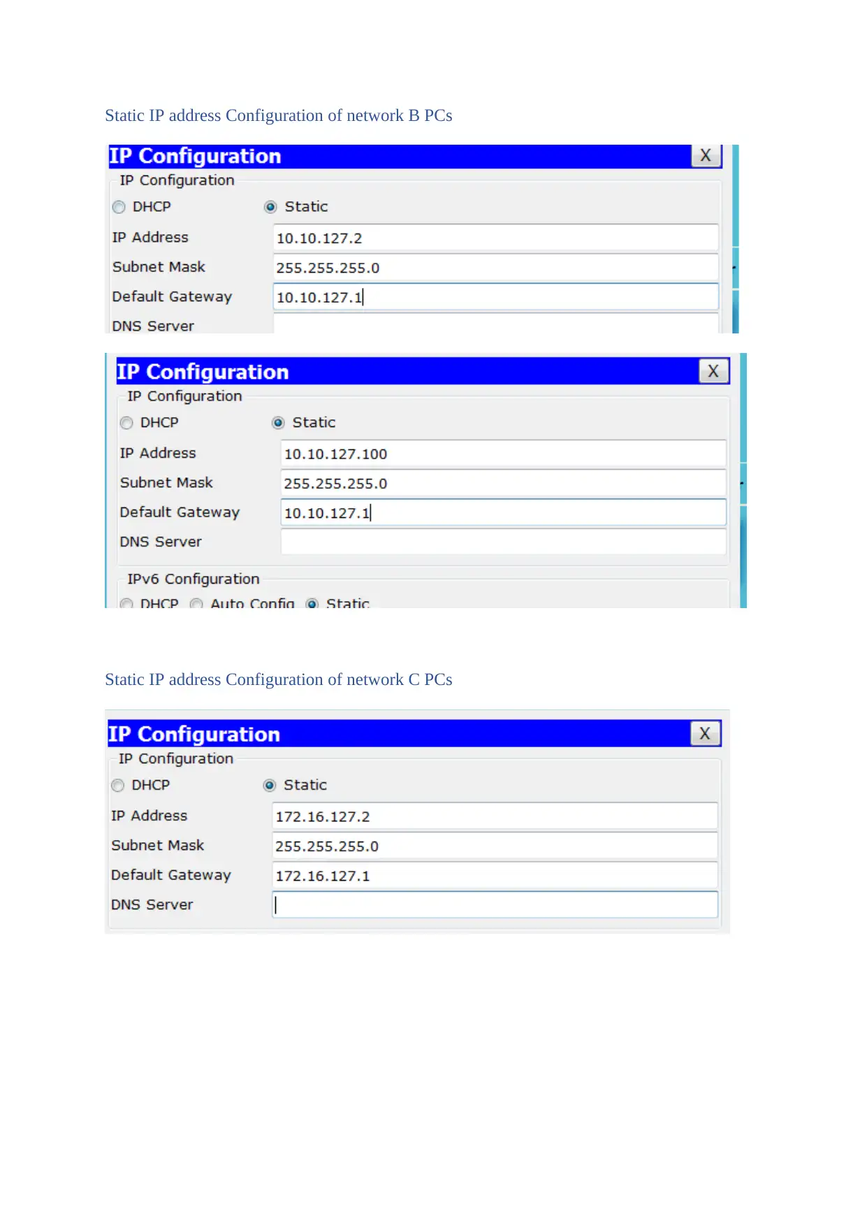
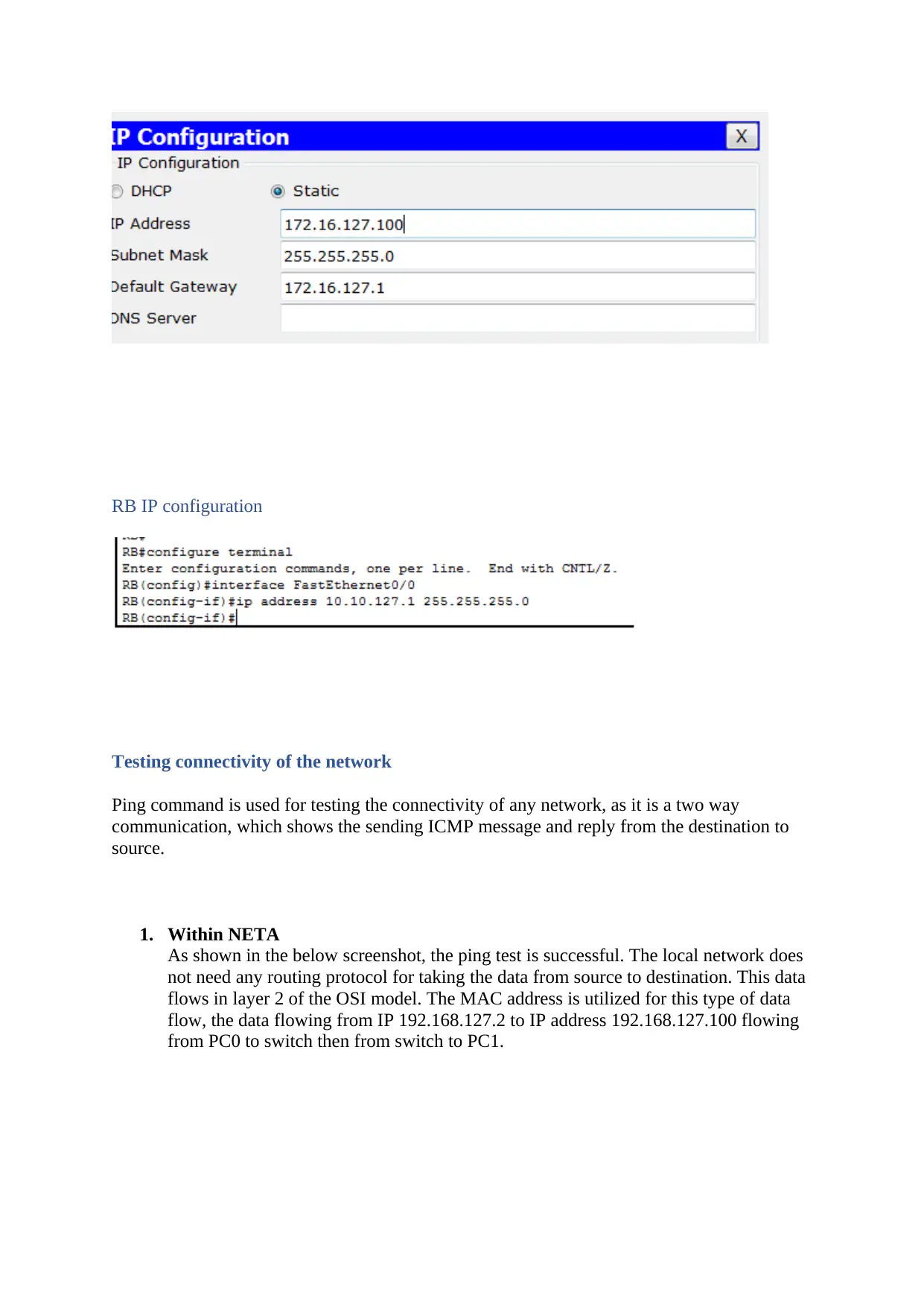
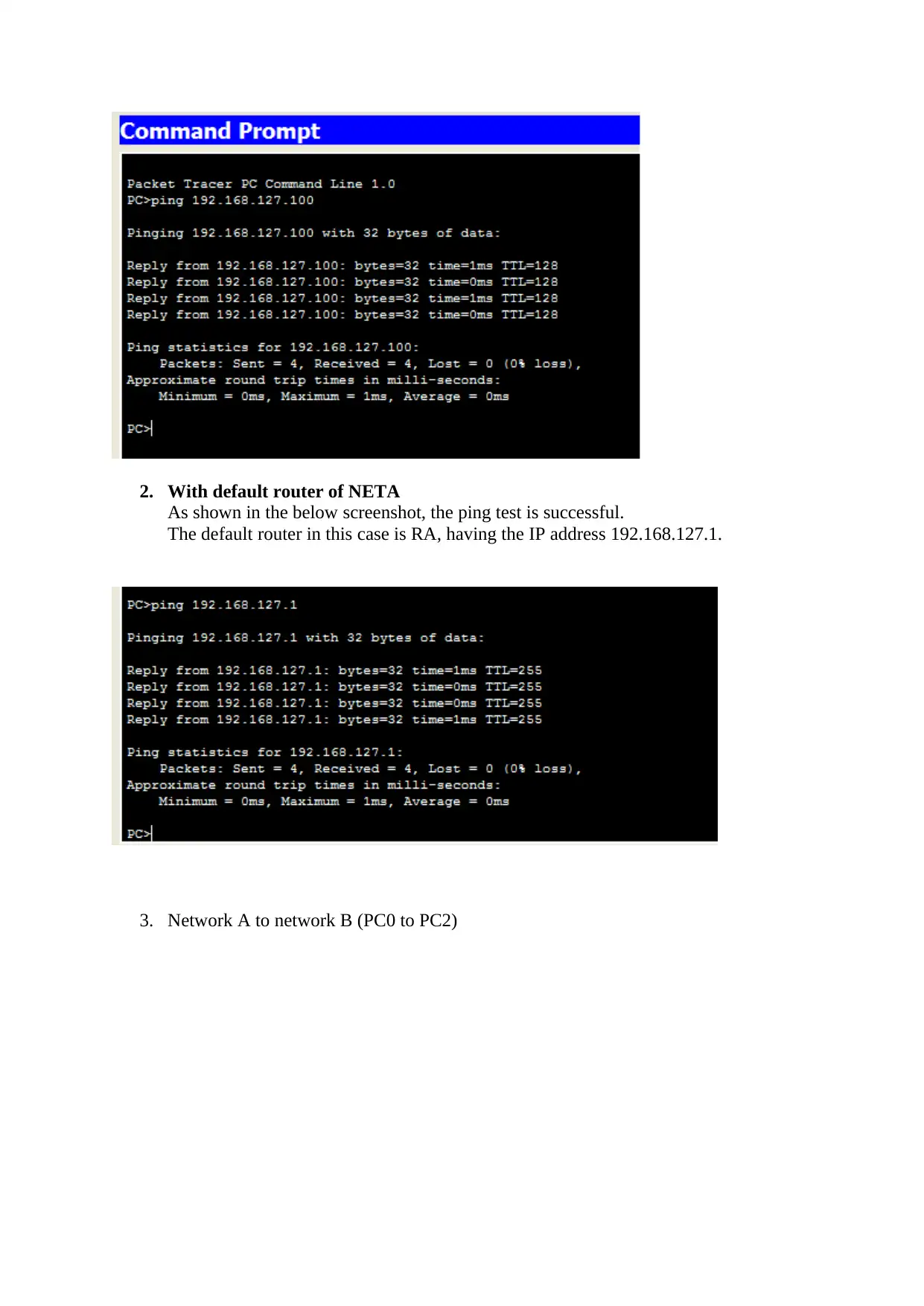
This report details the design and configuration of a computer network for ABC Company, addressing IP addressing, subnetting, and the implementation of the OSPF routing protocol across three routers and various networks. The report covers the configuration of router interfaces, static IP addresses for end hosts, and the testing of network connectivity using ping commands. Furthermore, the report explores cloud computing solutions for ABC Company, examining services like SaaS, IaaS, and PaaS, along with a comparison of cloud service providers such as AWS and Microsoft Azure. The report concludes with a discussion on the scalability of web applications in the cloud, highlighting the importance of dynamic scaling and auto-scaling techniques, particularly within the context of AWS. The document offers a comprehensive overview of network design, cloud computing, and scalability considerations for modern IT infrastructures.

planning and configuring a computer network.
[Document subtitle]
[DATE]
[Company name]
[Company address]
[Document subtitle]
[DATE]
[Company name]
[Company address]
Paraphrase This Document
Need a fresh take? Get an instant paraphrase of this document with our AI Paraphraser

Part A
Introduction
The computer network design and configuration is very crucial in success of any organization
now a days. In this assessment a network design is shown as given in the below figure, we
need to provide IT infrastructure solution to the organization as per the requirements. The
figure needs to be analysed and network configurations are given in this report.
Figure 1: Network design for ABC Company
For the computer diagram in Figure 1:
NET-A: 192.168.1XY.0/24
NET-B: 10.10.1XY.0/24
NET-C: 172.16.1XY.0/24
XY = student ID last two digit
As the student ID of one of the member of group is 27, so, IP address of network will be
given as
NET-A: 192.168.127.0/24
NET-B: 10.10.127.0/24
NET-C: 172.16.127.0/24

In this task you will fill the required information using the IP network diagram:
a. NET-A:
Network/Subnet: 192.168.127.0/24
Net mask: 255.255.255.0
Network address: 192.168.127.0
Broadcast address: 192.168.127.255
Valid host range:192.168.127.1 - 192.168.127.254 (total 254 hosts)
b. NET-B:
Network/Subnet: 10.10.127.0/24
Net mask: 255.255.255.0
Network address:10.10.127.0
Broadcast address:10.10.127.255
Valid host range:10.10.127.1- 10.10.127.254 (total 254 hosts)
c. NET-C:
Network/Subnet: 172.16.127.0/24
Net mask: 255.255.255.0
Network address:172.16.127.0
Broadcast address:172.16.127.255
Valid host range:172.16.127.1- 172.16.127.254 (total 254 hosts)
d. RA - RB subnet:255.255.255.0
e.RB - RC subnet:255.255.255.0
F.NetA subnet mask:255.255.255.0
Network Topology
The network topology shows the network connectivity, the network includes three routers,
three switches and six PCs. Network A has 2 Pcs which is connected to switch 0, the switch
is then connected to Router RA . The second router RB connects RA, RC and net B. The
third router RC connects Net C and RB . Each devices and ports of routers are given IP
address according to the project requirements.
⊘ This is a preview!⊘
Do you want full access?
Subscribe today to unlock all pages.

Trusted by 1+ million students worldwide

Table showing the IP address
Device Interface IP Address/ Subnet Mask
D/Gateway
RA Fa0/0 192.168.127.1/24 To NET A
S0/0/0 192.168.0.254/24 TO RB
RB Fa0/0 10.10.127.1/24 To NET B
S0/0/0 192.168.0.253/24 TO RA
S0/0/1 192.168.1.249/24 TO RC
RC Fa0/0 172.16.127.1/24 To NET C
S0/0/1 192.168.1.250/24 TO RB
Device Interface IP Address/ Subnet Mask
D/Gateway
RA Fa0/0 192.168.127.1/24 To NET A
S0/0/0 192.168.0.254/24 TO RB
RB Fa0/0 10.10.127.1/24 To NET B
S0/0/0 192.168.0.253/24 TO RA
S0/0/1 192.168.1.249/24 TO RC
RC Fa0/0 172.16.127.1/24 To NET C
S0/0/1 192.168.1.250/24 TO RB
Paraphrase This Document
Need a fresh take? Get an instant paraphrase of this document with our AI Paraphraser

Configure router RA interfaces:
RA(config)#:int F0/0
RA(config-if)#:ip address 192.168.127.1 255.255.255.0
RA(config-if)#: no shutdown
Figure: screenshot for the IP address configuration in RA
RA(config)#:int S0/0/0
RA(config-if)#:ip address 192.168.0.254 255.255.255.255.0
RA(config-if)#:clock rate 6400
Figure: screenshot for the IP address configuration in RA
Configure Routing Protocol
OSPF (open shortest path first) routing protocol is used for configuring Routers . In this
protocol, a router checks the neighbour IP address and cost for that link and creates routing
table. When data flows through the routers from one network to another network, this routing
table is used.
RA(config)#:router ospf 20
RA(config-router)#: network 192.168.127.0 0.0.0.255 area 0
RA(config-router)#:network 192.168.127.0 0.0.0.255 area 0

The below figure shows all the IP routes or routing table of RA.
Provide commands to enable routing protocol in RB (same protocol configured in RA)
RB(config)#:router ospf 20
RB(config-router)#:network 192.168.0.0 0.0.0.255 area 0
RB(config-router)#:network 192.168.1.0 0.0.0.255 area 0
RB(config-router)#:network 10.10.127.0 0.0.0.255 area 0
The below figure shows all the IP routes or routing table of RB.
⊘ This is a preview!⊘
Do you want full access?
Subscribe today to unlock all pages.

Trusted by 1+ million students worldwide

Provide commands to enable routing protocol in RC (same protocol configured in RA)
RC(config)#:router ospf 20
RC(config-router)#:network 192.168.1.0 0.0.0.255 area 0
RC(config-router)#:network 172.16.127.0 0.0.0.255 area 0
The below figure shows all the IP routes or routing table of RC.
RC(config)#:router ospf 20
RC(config-router)#:network 192.168.1.0 0.0.0.255 area 0
RC(config-router)#:network 172.16.127.0 0.0.0.255 area 0
The below figure shows all the IP routes or routing table of RC.
Paraphrase This Document
Need a fresh take? Get an instant paraphrase of this document with our AI Paraphraser

Static IP address Configuration of network A PCs
The IP address of each end hosts needs to be given for identifying the address , as source or
destination in data flow in the network.
The IP address of each end hosts needs to be given for identifying the address , as source or
destination in data flow in the network.

⊘ This is a preview!⊘
Do you want full access?
Subscribe today to unlock all pages.

Trusted by 1+ million students worldwide

Static IP address Configuration of network B PCs
Static IP address Configuration of network C PCs
Paraphrase This Document
Need a fresh take? Get an instant paraphrase of this document with our AI Paraphraser

RB IP configuration
Testing connectivity of the network
Ping command is used for testing the connectivity of any network, as it is a two way
communication, which shows the sending ICMP message and reply from the destination to
source.
1. Within NETA
As shown in the below screenshot, the ping test is successful. The local network does
not need any routing protocol for taking the data from source to destination. This data
flows in layer 2 of the OSI model. The MAC address is utilized for this type of data
flow, the data flowing from IP 192.168.127.2 to IP address 192.168.127.100 flowing
from PC0 to switch then from switch to PC1.

2. With default router of NETA
As shown in the below screenshot, the ping test is successful.
The default router in this case is RA, having the IP address 192.168.127.1.
3. Network A to network B (PC0 to PC2)
As shown in the below screenshot, the ping test is successful.
The default router in this case is RA, having the IP address 192.168.127.1.
3. Network A to network B (PC0 to PC2)
⊘ This is a preview!⊘
Do you want full access?
Subscribe today to unlock all pages.

Trusted by 1+ million students worldwide
1 out of 20
Related Documents

Your All-in-One AI-Powered Toolkit for Academic Success.
+13062052269
info@desklib.com
Available 24*7 on WhatsApp / Email
Unlock your academic potential
Copyright © 2020–2025 A2Z Services. All Rights Reserved. Developed and managed by ZUCOL.