Network Infrastructure Setup and Configuration for Alm.co.uk Network
VerifiedAdded on Ā 2022/11/19
|19
|2746
|13
Report
AI Summary
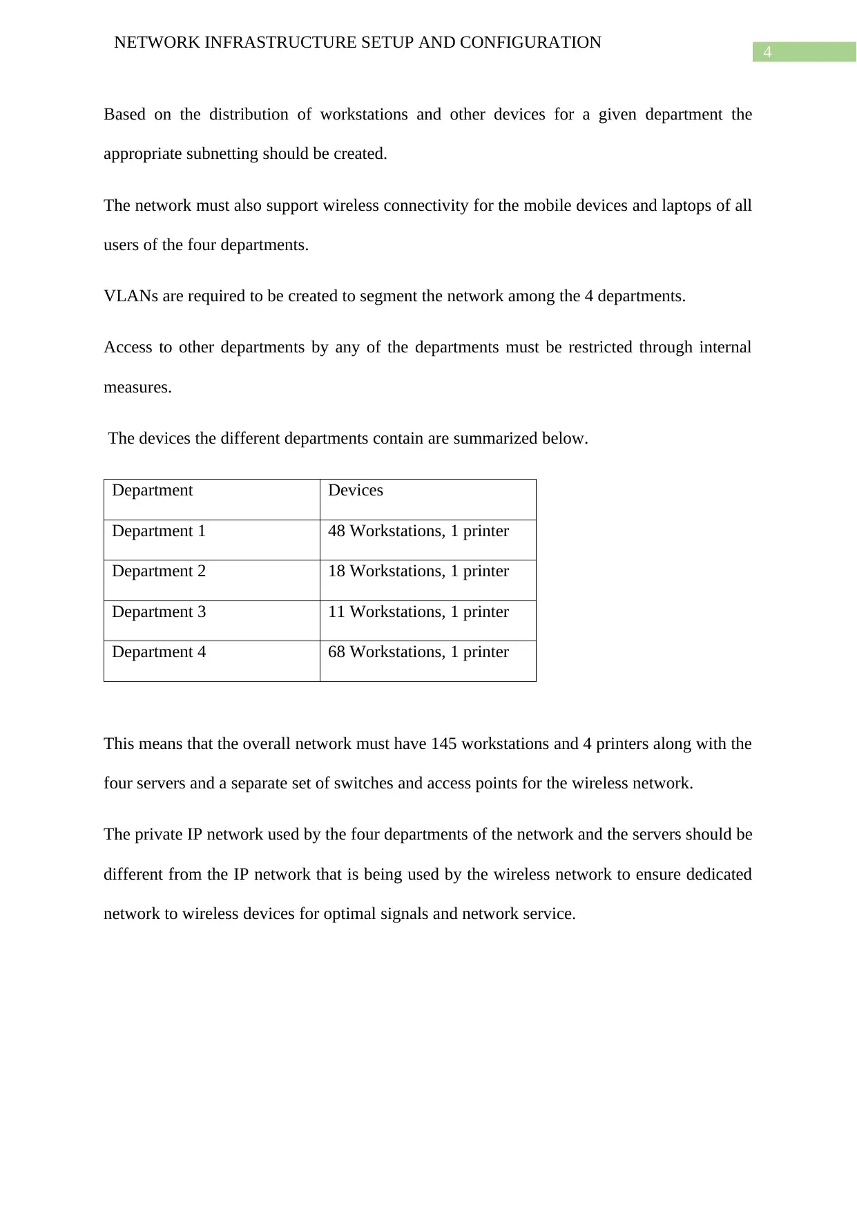
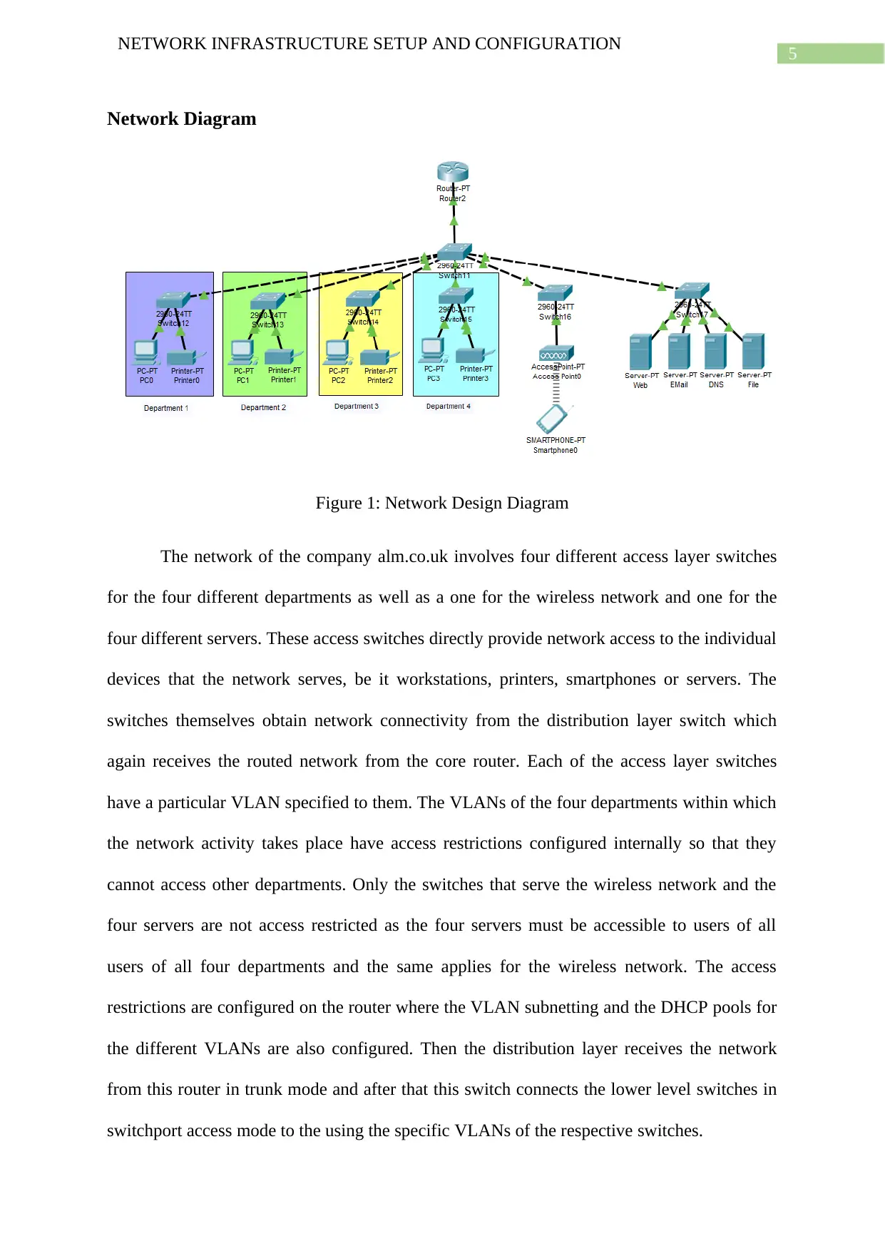
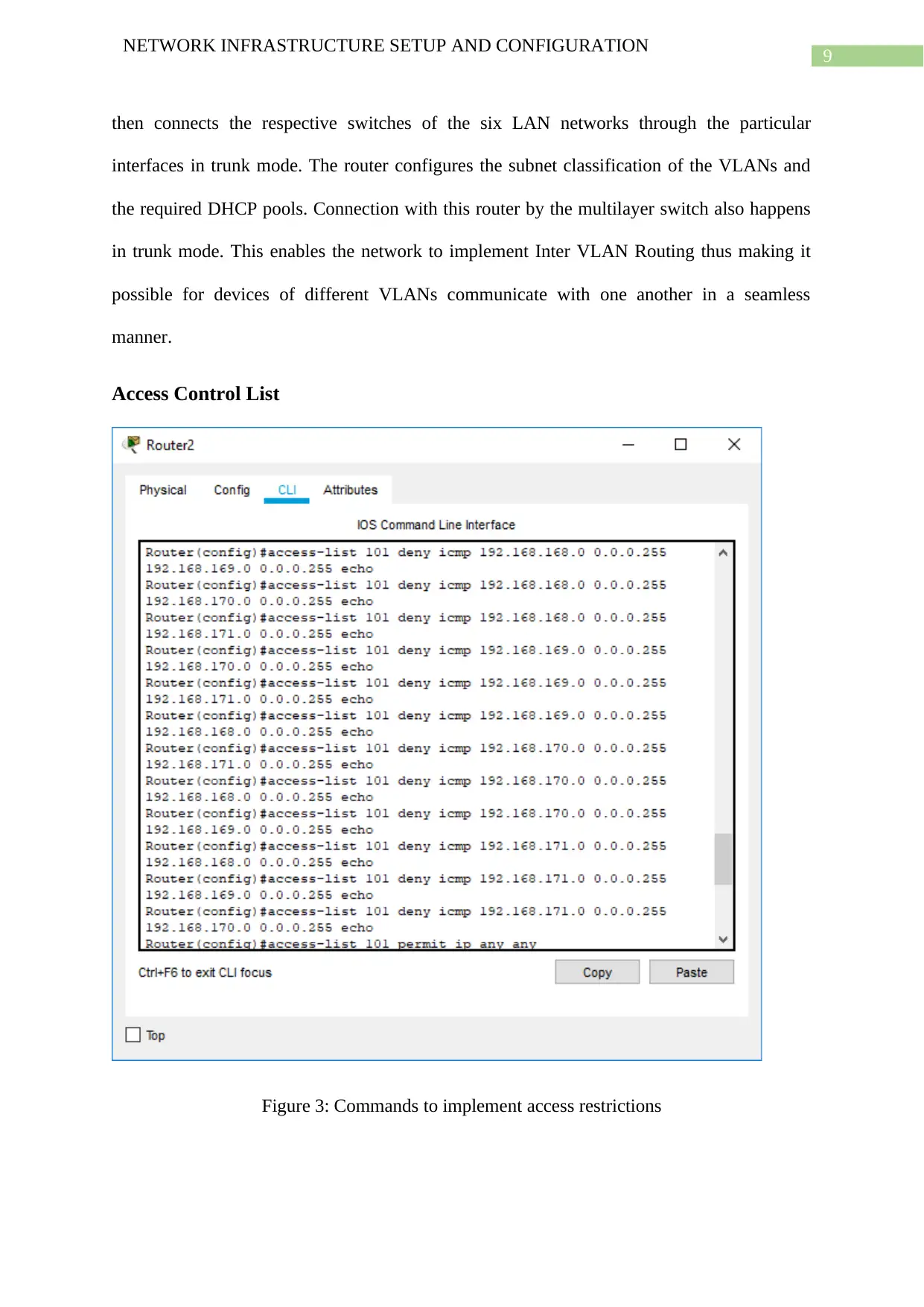
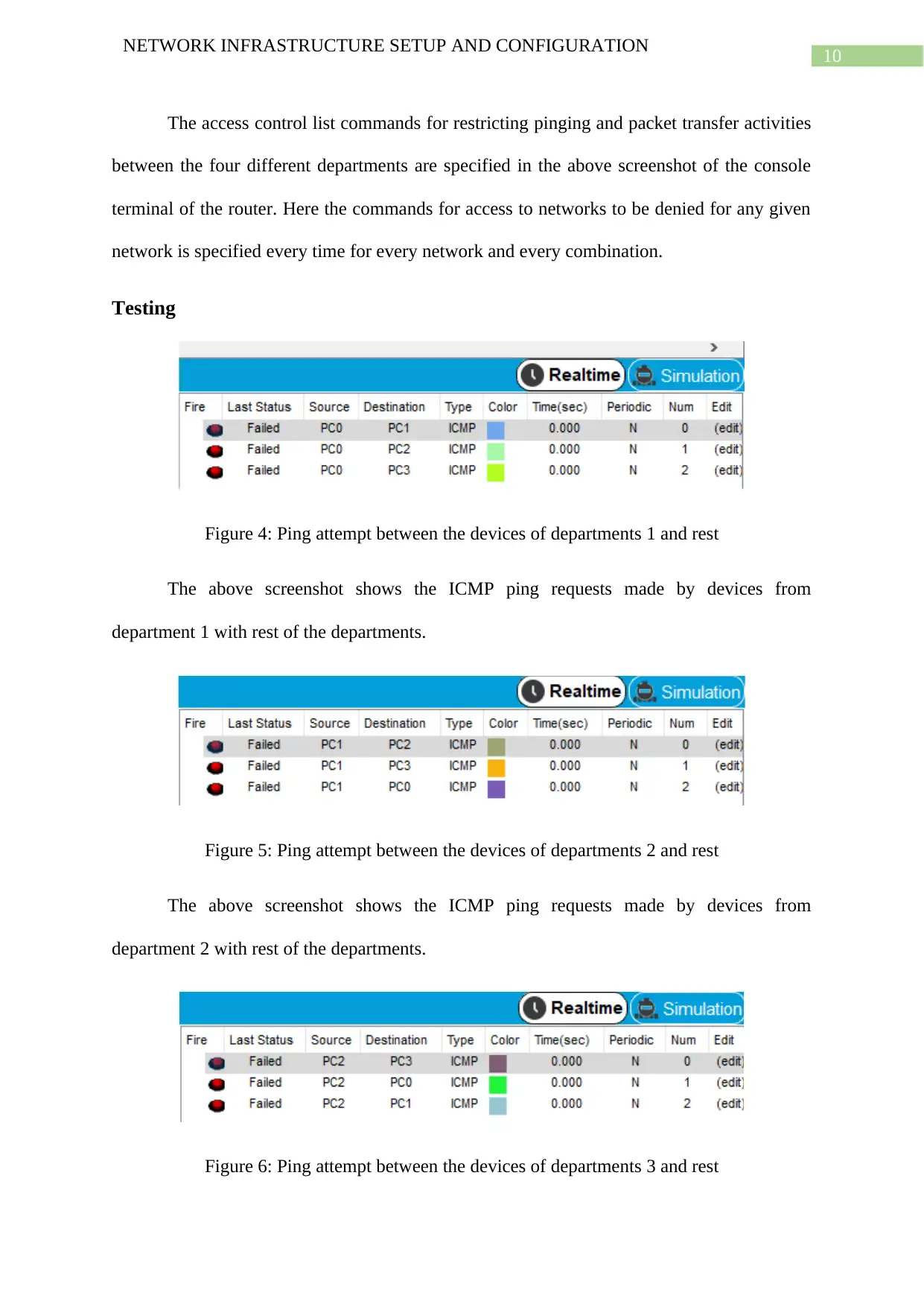
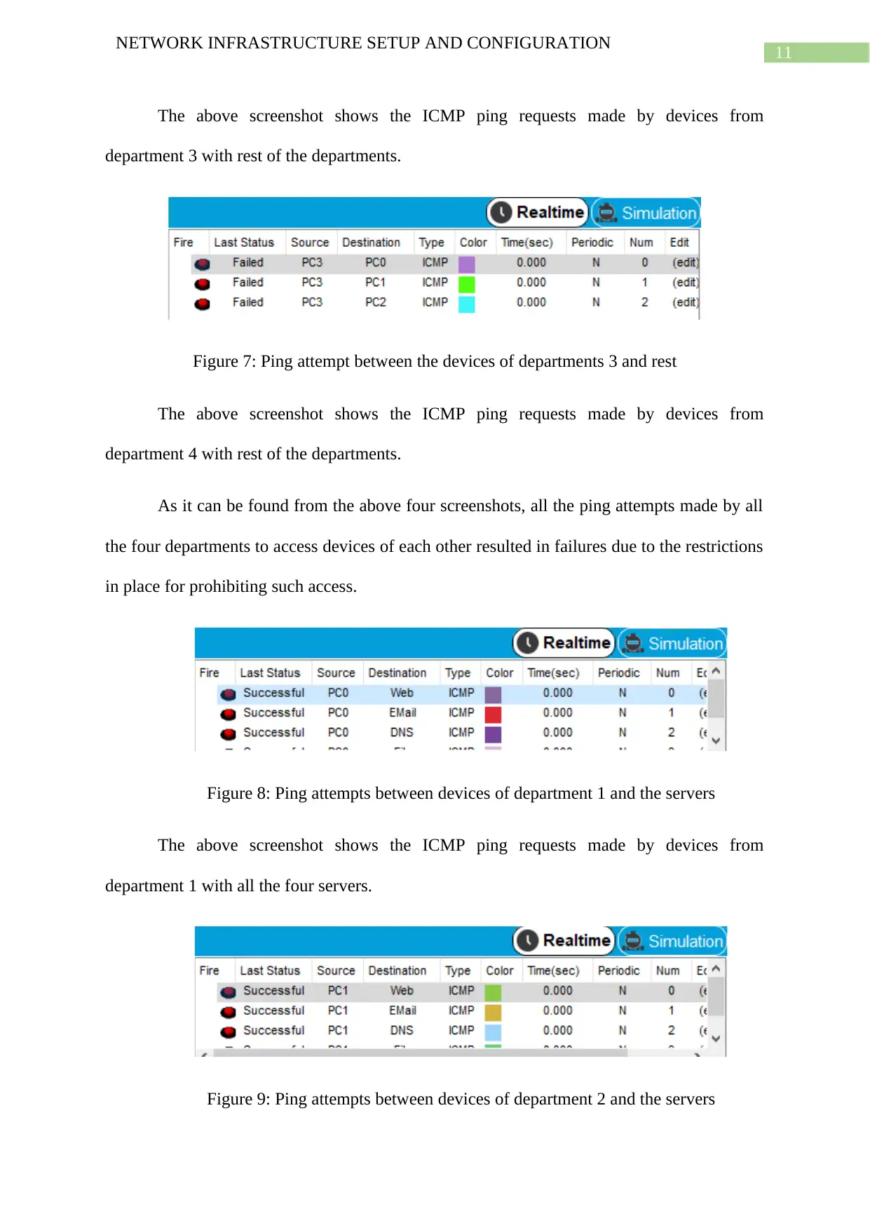
This report presents a comprehensive network infrastructure design for alm.co.uk, focusing on segmentation and security. It begins by outlining the network requirements, including the need for four departments, four servers (web, email, DNS, and file), and wireless connectivity. The report then details the network diagram, illustrating the use of access layer switches, a distribution layer switch, and a core router. It explains the implementation of VLANs to segment the network, along with subnetting details for each segment, including IP addresses, subnet masks, and CIDR values. The report also covers the use of access control lists to restrict inter-departmental access and provides testing results to verify the effectiveness of these restrictions. Finally, the report discusses the use of DHCP for IP address allocation and concludes with a summary of the network's successful implementation and its ability to meet the specified requirements.

Running head: NETWORK INFRASTRUCTURE SETUP AND CONFIGURATION
Network Infrastructure Setup and Configuration
Name of the Student
Name of the University
Author Note
Network Infrastructure Setup and Configuration
Name of the Student
Name of the University
Author Note
Paraphrase This Document
Need a fresh take? Get an instant paraphrase of this document with our AI Paraphraser

1
NETWORK INFRASTRUCTURE SETUP AND CONFIGURATION
Summary
Segmenting networks play an important role in ensuring security and privacy within a
network. The network being proposed by the report tries to implement one such network for
alm.co.uk and segments it by using different VLANs for the different use cases including
subnetworks of the four departments. First the report lays down the requirements of the
network and summarizes the device requirements of the four departments in a tabular format.
Then the report presents the network design diagram after which the report discusses the
implementation of the network as well as justifies it. After that the report provides the
subnetting details of the various segments and highlights the networks, subnet masks and
CIDR for each segment. Thereafter the six different VLANs of the six segments are talked
about and the subnetworks they serve is noted. The report also explains how the departments
get restricted from accessing other departments using the access control list extended
commands. Then testing is conducted on whether the access restrictions are effective and if
the devices are able to automatically obtain IP addresses using the DHCP protocol. After this
the report ends with concluding notes.

2
NETWORK INFRASTRUCTURE SETUP AND CONFIGURATION
Table of Contents
Introduction................................................................................................................................3
Discussion..................................................................................................................................3
Requirements..........................................................................................................................3
Network Diagram...................................................................................................................5
Subnet Details........................................................................................................................6
VLAN.....................................................................................................................................8
Access Control List................................................................................................................9
Testing..................................................................................................................................10
DHCP...................................................................................................................................13
Conclusion................................................................................................................................15
Bibliography.............................................................................................................................17
ā This is a preview!ā
Do you want full access?
Subscribe today to unlock all pages.

Trusted by 1+ million students worldwide

3
NETWORK INFRASTRUCTURE SETUP AND CONFIGURATION
Introduction
It is because segmenting networks play a vital role to ensure security and privacy in
networks, the report proposes a network for alm.co.uk where it tries to implement such
segmentations with the help of VLANs for the different use cases including subnetworks of
the four departments. The report begins by laying down the requirements of the network and
summarizes the device requirements of the four departments in a tabular format. Then the
report presents the network design diagram after which the report discusses the
implementation of the network as well as justifies it. After that the report provides the
subnetting details of the various segments and highlights the networks, subnet masks and
CIDR for each segment. Thereafter the six different VLANs of the six segments are talked
about and the subnetworks they serve is noted. The report also explains how the departments
get restricted from accessing other departments using the access control list extended
commands. Then testing is conducted on whether the access restrictions are effective and if
the devices are able to automatically obtain IP addresses using the DHCP protocol. After this
the report ends with concluding notes.
Discussion
Requirements
The network of the client company alm.co.uk must consist of four departments.
The network should additionally contain four servers, namely the web server, the email
server, the DNS server and the file server.
All of these servers are required to be shared among all the respective users of the different
departments.
Paraphrase This Document
Need a fresh take? Get an instant paraphrase of this document with our AI Paraphraser

4
NETWORK INFRASTRUCTURE SETUP AND CONFIGURATION
Based on the distribution of workstations and other devices for a given department the
appropriate subnetting should be created.
The network must also support wireless connectivity for the mobile devices and laptops of all
users of the four departments.
VLANs are required to be created to segment the network among the 4 departments.
Access to other departments by any of the departments must be restricted through internal
measures.
The devices the different departments contain are summarized below.
Department Devices
Department 1 48 Workstations, 1 printer
Department 2 18 Workstations, 1 printer
Department 3 11 Workstations, 1 printer
Department 4 68 Workstations, 1 printer
This means that the overall network must have 145 workstations and 4 printers along with the
four servers and a separate set of switches and access points for the wireless network.
The private IP network used by the four departments of the network and the servers should be
different from the IP network that is being used by the wireless network to ensure dedicated
network to wireless devices for optimal signals and network service.

5
NETWORK INFRASTRUCTURE SETUP AND CONFIGURATION
Network Diagram
Figure 1: Network Design Diagram
The network of the company alm.co.uk involves four different access layer switches
for the four different departments as well as a one for the wireless network and one for the
four different servers. These access switches directly provide network access to the individual
devices that the network serves, be it workstations, printers, smartphones or servers. The
switches themselves obtain network connectivity from the distribution layer switch which
again receives the routed network from the core router. Each of the access layer switches
have a particular VLAN specified to them. The VLANs of the four departments within which
the network activity takes place have access restrictions configured internally so that they
cannot access other departments. Only the switches that serve the wireless network and the
four servers are not access restricted as the four servers must be accessible to users of all
users of all four departments and the same applies for the wireless network. The access
restrictions are configured on the router where the VLAN subnetting and the DHCP pools for
the different VLANs are also configured. Then the distribution layer receives the network
from this router in trunk mode and after that this switch connects the lower level switches in
switchport access mode to the using the specific VLANs of the respective switches.
ā This is a preview!ā
Do you want full access?
Subscribe today to unlock all pages.

Trusted by 1+ million students worldwide

6
NETWORK INFRASTRUCTURE SETUP AND CONFIGURATION
Subnet Details
Subnet
Name
Need
ed
Size
Alloca
ted
Size
Address
Ma
sk
Dec Mask
Assignable
Range
Broadcast
Depart
ment 1
49 62
192.168.16
8.128
/26
255.255.25
5.192
192.168.16
8.129 -
192.168.16
8.190
192.168.16
8.191
Depart
ment 2
19 30
192.168.16
9.0
/27
255.255.25
5.224
192.168.16
9.1 -
192.168.16
9.30
192.168.16
9.31
Depart
ment 3
12 14
192.168.17
0.0
/28
255.255.25
5.240
192.168.17
0.1 -
192.168.17
0.14
192.168.17
0.15
Depart
ment 4
69 126
192.168.17
1.0
/25
255.255.25
5.128
192.168.17
1.1 -
192.168.17
1.126
192.168.17
1.127
Servers 4 6
192.168.17
2.0
/29
255.255.25
5.248
192.168.17
2.1 -
192.168.17
2.6
192.168.17
2.7
Wireles 145 254 10.11.12.0 /24 255.255.25 10.11.12.1 - 10.11.12.25
Paraphrase This Document
Need a fresh take? Get an instant paraphrase of this document with our AI Paraphraser

7
NETWORK INFRASTRUCTURE SETUP AND CONFIGURATION
s
Networ
k
5.0
10.11.12.25
4
5
The different subnets required for creating the 6 different subnetworks are given in
the above table. The four departments of the company use the subnetworks 192.168.168.0,
192.168.169.0, 192.168.170.0 and 192.168.171.0. The four servers present in the network use
the subnetwork 192.168.172.0. Lastly the wireless network uses the subnetwork 10.11.12.0.
The subnet masks for the given networks are 255.255.255.192, 255.255.255.224,
255.255.255.240, 255.255.255.128, 255.255.255.248 and 255.255.255.0 respectively and the
corresponding CIDR values of the subnets are /26, /27, /28, /25, /29, /24 in the order they are
listed.
The CIDR addressing scheme is chosen over the conventional classful IP addressing scheme
since the CIDR scheme offers smoother transitions the available IP address spaces with every
changes in the CIDR mask values. In contrast in classful IP addressing scheme change in
number of available host IPs in address space when transitioning from class A to class B or
from class B to class C is drastically large. This, most of the time results in wastage of IP
addresses or want of it.

8
NETWORK INFRASTRUCTURE SETUP AND CONFIGURATION
VLAN
Figure 2: VLANs for the different segments of the network
The six VLANs that have been created for the different segments of the network are
the VLAN names that start with the letter āVā. The VLAN V12 is created for the subnetwork
of the wireless network. The VLAN V172 is created for the subnetwork of the servers. The
VLANs V168, V169, V170 and V171 are created for the subnetworks of the four different
departments. The multilayer switch contains the database of all the six VLANs, four for the
different departments and the other two for the servers and the wireless network. This switch
ā This is a preview!ā
Do you want full access?
Subscribe today to unlock all pages.

Trusted by 1+ million students worldwide

9
NETWORK INFRASTRUCTURE SETUP AND CONFIGURATION
then connects the respective switches of the six LAN networks through the particular
interfaces in trunk mode. The router configures the subnet classification of the VLANs and
the required DHCP pools. Connection with this router by the multilayer switch also happens
in trunk mode. This enables the network to implement Inter VLAN Routing thus making it
possible for devices of different VLANs communicate with one another in a seamless
manner.
Access Control List
Figure 3: Commands to implement access restrictions
Paraphrase This Document
Need a fresh take? Get an instant paraphrase of this document with our AI Paraphraser

10
NETWORK INFRASTRUCTURE SETUP AND CONFIGURATION
The access control list commands for restricting pinging and packet transfer activities
between the four different departments are specified in the above screenshot of the console
terminal of the router. Here the commands for access to networks to be denied for any given
network is specified every time for every network and every combination.
Testing
Figure 4: Ping attempt between the devices of departments 1 and rest
The above screenshot shows the ICMP ping requests made by devices from
department 1 with rest of the departments.
Figure 5: Ping attempt between the devices of departments 2 and rest
The above screenshot shows the ICMP ping requests made by devices from
department 2 with rest of the departments.
Figure 6: Ping attempt between the devices of departments 3 and rest

11
NETWORK INFRASTRUCTURE SETUP AND CONFIGURATION
The above screenshot shows the ICMP ping requests made by devices from
department 3 with rest of the departments.
Figure 7: Ping attempt between the devices of departments 3 and rest
The above screenshot shows the ICMP ping requests made by devices from
department 4 with rest of the departments.
As it can be found from the above four screenshots, all the ping attempts made by all
the four departments to access devices of each other resulted in failures due to the restrictions
in place for prohibiting such access.
Figure 8: Ping attempts between devices of department 1 and the servers
The above screenshot shows the ICMP ping requests made by devices from
department 1 with all the four servers.
Figure 9: Ping attempts between devices of department 2 and the servers
ā This is a preview!ā
Do you want full access?
Subscribe today to unlock all pages.

Trusted by 1+ million students worldwide
1 out of 19
Related Documents
Your All-in-One AI-Powered Toolkit for Academic Success.
Ā +13062052269
info@desklib.com
Available 24*7 on WhatsApp / Email
Unlock your academic potential
Copyright Ā© 2020ā2025 A2Z Services. All Rights Reserved. Developed and managed by ZUCOL.


