Network Design & Troubleshooting: ALM Network Access Restrictions
VerifiedAdded on 2022/10/10
|20
|3559
|11
Report
AI Summary
This report provides a detailed solution for implementing a secure and segmented network for alm.co.uk. It begins by outlining the network requirements, including the number of devices per department, access restrictions, server configurations, and subnet classifications. The report then presents a network design created using Cisco Packet Tracer 6.2, explaining the three-layered hierarchical model (core, distribution, and access layers). Subnetting is thoroughly discussed, with a table detailing subnet sizes, network addresses, CIDR notation, subnet masks, and IP address ranges for each department, servers, and the wireless network. VLAN implementation is demonstrated, showing how VLANs are configured for inter-VLAN routing. Access Control Lists (ACLs) are implemented to restrict inter-departmental access, with specific ACL commands provided. The report includes validation tests to confirm that the implemented network meets the specified requirements, such as blocking inter-departmental ping messages while allowing access to servers and the wireless network. Finally, the report discusses IP addressing protocols and concludes with key takeaways.
Running head: NETWORK IMPLEMENTATION AND ACCESS RESTRICTIONS
Network Implementation and Access Restrictions
Name of the Student
Name of the University
Author Note
Network Implementation and Access Restrictions
Name of the Student
Name of the University
Author Note
Paraphrase This Document
Need a fresh take? Get an instant paraphrase of this document with our AI Paraphraser
1
NETWORK IMPLEMENTATION AND ACCESS RESTRICTIONS
Summary
As of present day, segmentation of networks and internally securing of these network
segments play a significant role in preventing networks from getting compromised by threats
of hackers, and other cyber security attacks. The report proposes a network for alm.co.uk
where such segmentation are created and appropriate security measures for these segments
are put in place. First the report summarizes the requirements of ALM network where the
number of devices for each segment, the access restrictions, and the kinds of servers installed,
and the specific subnet classifications are mentioned. Then the report provides the network
design which has been drawn and configured in Cisco Packet Tracer 6.2 after which the
network design and architecture gets explained in detail. Next the IP addressing and the
subnet classifications of the network is provided in tabular format and discussed thereafter
with respect to the subnets for each segment. Then the implementation of the VLANs is
shown, and the report discusses how the VLANs get implemented to ensure the inter VLAN
routing works. Thereafter the report talks about the access control list extended commands
for prohibiting the departments from accessing one another. All restrictions available through
ACL commands is shown as well as how the departments are restricted. Next the report
provides the tests and validations to check whether the network proposed meets the
requirements of AML. Then after discussing the IP addressing protocol the report ends with
concluding notes.
2
NETWORK IMPLEMENTATION AND ACCESS RESTRICTIONS
Table of Contents
Introduction................................................................................................................................3
Requirements..............................................................................................................................3
Solution......................................................................................................................................4
Network Design.....................................................................................................................4
Subnetting of the network......................................................................................................5
VLAN Implementation..........................................................................................................8
VLAN Access Restrictions using Access Control List..........................................................9
Validation and Tests.............................................................................................................11
Protocols for connecting devices.........................................................................................14
Conclusion................................................................................................................................15
References................................................................................................................................16
⊘ This is a preview!⊘
Do you want full access?
Subscribe today to unlock all pages.
Trusted by 1+ million students worldwide
3
NETWORK IMPLEMENTATION AND ACCESS RESTRICTIONS
Introduction
The following report highlights the importance of segmentation of networks and
internally securing of these network segments play a significant role in preventing networks
from getting compromised by threats of hackers, and other cyber security attacks. The report
aims to propose a network for alm.co.uk where such segmentation are created and
appropriate security measures for these segments are put in place. The report begins by
summarizing the requirements of ALM network where the number of devices for each
segment, the access restrictions, and the kinds of servers installed, and the specific subnet
classifications are mentioned. Then the report provides the network design which has been
drawn and configured in Cisco Packet Tracer 6.2 after which the network design and
architecture gets explained in detail. Next the IP addressing and the subnet classifications of
the network is provided in tabular format and discussed thereafter with respect to the subnets
for each segment. Then the implementation of the VLANs is shown, and the report discusses
how the VLANs get implemented to ensure the inter VLAN routing works. Thereafter the
report talks about the access control list extended commands for prohibiting the departments
from accessing one another. All restrictions available through ACL commands is shown as
well as how the departments are restricted. Next the report provides the tests and validations
to check whether the network proposed meets the requirements of AML. Then after
discussing the IP addressing protocol the report ends with concluding notes.
Requirements
The small network of the company alm.co.uk is to consist of four different LAN
configurations for four different departments along with LAN configuration for the servers
and the wireless network.
Paraphrase This Document
Need a fresh take? Get an instant paraphrase of this document with our AI Paraphraser
4
NETWORK IMPLEMENTATION AND ACCESS RESTRICTIONS
The LAN configuration of the servers include individual servers for DNS, email, web and
File sharing purposes.
Each and every server needs to have access with the individual workstations of users of all
the four departments.
Subnet classification of ALM network needs to be made as per the count of workstations,
printers, servers the different departments.
ALM’s network is to have wireless network support for the various smartphones and laptops
belonging to users of all departments.
This network then needs to be segmented so that network access to and from the devices of
the four departments as also other LAN configurations of the network can be better controlled
and managed with specified access rules.
Each department must be blocked from accessing systems of other three departments via
security restrictions implemented internally.
The number of workstations and printers which exist in the four separate departments can be
given by 48 PCs as well as 1 printer for Dept. 1, 18 workstations along with 1 printer for
Dept. 2, 11 workstations and 1 printer for Dept. 3 and upto 68 workstations as also 1 printer
for the Dept. 4.
5
NETWORK IMPLEMENTATION AND ACCESS RESTRICTIONS
Solution
Network Design
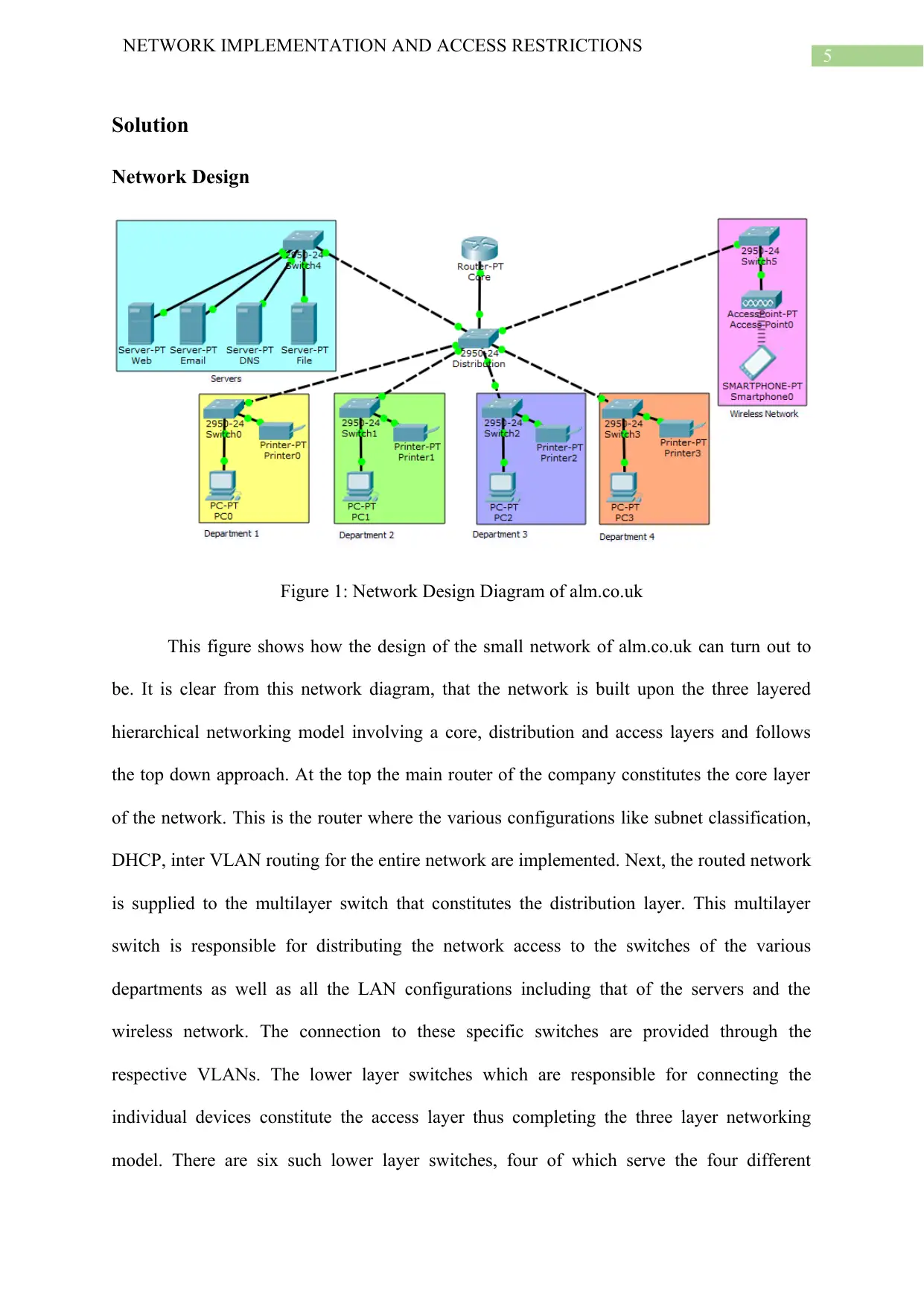
Figure 1: Network Design Diagram of alm.co.uk
This figure shows how the design of the small network of alm.co.uk can turn out to
be. It is clear from this network diagram, that the network is built upon the three layered
hierarchical networking model involving a core, distribution and access layers and follows
the top down approach. At the top the main router of the company constitutes the core layer
of the network. This is the router where the various configurations like subnet classification,
DHCP, inter VLAN routing for the entire network are implemented. Next, the routed network
is supplied to the multilayer switch that constitutes the distribution layer. This multilayer
switch is responsible for distributing the network access to the switches of the various
departments as well as all the LAN configurations including that of the servers and the
wireless network. The connection to these specific switches are provided through the
respective VLANs. The lower layer switches which are responsible for connecting the
individual devices constitute the access layer thus completing the three layer networking
model. There are six such lower layer switches, four of which serve the four different
NETWORK IMPLEMENTATION AND ACCESS RESTRICTIONS
Solution
Network Design
Figure 1: Network Design Diagram of alm.co.uk
This figure shows how the design of the small network of alm.co.uk can turn out to
be. It is clear from this network diagram, that the network is built upon the three layered
hierarchical networking model involving a core, distribution and access layers and follows
the top down approach. At the top the main router of the company constitutes the core layer
of the network. This is the router where the various configurations like subnet classification,
DHCP, inter VLAN routing for the entire network are implemented. Next, the routed network
is supplied to the multilayer switch that constitutes the distribution layer. This multilayer
switch is responsible for distributing the network access to the switches of the various
departments as well as all the LAN configurations including that of the servers and the
wireless network. The connection to these specific switches are provided through the
respective VLANs. The lower layer switches which are responsible for connecting the
individual devices constitute the access layer thus completing the three layer networking
model. There are six such lower layer switches, four of which serve the four different
⊘ This is a preview!⊘
Do you want full access?
Subscribe today to unlock all pages.
Trusted by 1+ million students worldwide
6
NETWORK IMPLEMENTATION AND ACCESS RESTRICTIONS
departments of alm.co.uk whereas the other two switches form the LAN configurations of the
servers as well as the wireless network. There are four servers installed in the network. These
are for the web server, the mail server, the DNS server and the file sharing server. While the
network is segmented by implementing VLANs for each LAN configuration, access to and
from the various departments is managed through the access control list extended commands.
Subnetting of the network
Sub
net
Nam
es
Sub
net
Size
Alloc
ated
subne
t size
Subnet
Network
Address
Subnet
CIDR
Subnet
Mask
IP
Address
Ranges
for
Subnet
Subnet
Broadcast
Address
Dept
. 1
49 62
192.168.
168.0
/26
255.255.2
55.192
192.168.1
68.1 -
192.168.1
68.62
192.168.1
68.63
Dept
. 2
19 30
192.168.
169.0
/27
255.255.2
55.224
192.168.1
69.1 -
192.168.1
69.30
192.168.1
69.31
Dept
. 3
12 14
192.168.
170.0
/28
255.255.2
55.240
192.168.1
70.1 -
192.168.1
70.14
192.168.1
70.15
Dept
. 4
69 126 192.168.
171.0
/25 255.255.2
5.128
192.168.1
71.1 -
192.168.1
Paraphrase This Document
Need a fresh take? Get an instant paraphrase of this document with our AI Paraphraser
7
NETWORK IMPLEMENTATION AND ACCESS RESTRICTIONS
192.168.1
71.126
71.127
Serve
r
LAN
4 6
192.168.
172.0
29
255.255.2
55.248
192.168.1
72.1 -
192.168.1
72.6
192.168.1
72.7
Wirel
ess
Netw
ork
LAN
250 254
10.11.12.
0
/24
255.255.2
55.0
10.11.12.1
-
10.11.12.2
54
10.11.12.2
55
The table provided above presents the different subnets that have been calculated for
six different subnets based on the private network 192.168.X.0/24. Here X is the varying part
of the network for each of the five subnets – four for different departments and one for the
servers. This is because the access routes are configured through inter VLAN routing and
each segment has their own specific VLAN. Both the servers and the wireless network should
be accessible by devices of the four departments. Since the wireless network is to provide
wireless connectivity to multiple devices of users of all departments, a full subnet is allocated
for this segment. The wireless network uses the private network 10.11.12.0/24. Therefore, the
subnet network addresses for the different departments happen to be 192.168.168.0 for Dept.
1, 192.168.169.0 for Dept. 2, 192.168.170.0 for Dept. 3, 192.168.171.0 for Dept. 4,
192.168.172.0 for servers and 10.11.12.0 for the wireless network. Subnet masks of these
different subnets can be given by 255.255.255.192 for Dept. 1, 255.255.255.224 for Dept. 2,
255.255.255.240 for Dept. 3, 255.255.255.128 Dept. 4, 255.255.255.248 for the servers, and
8
NETWORK IMPLEMENTATION AND ACCESS RESTRICTIONS
255.255.255.0 for the wireless network and the specific CIDR notations for these subnets are
26, 27, 28, 25, 29 and 24 respectively denoted in the form ‘/24’. This just means that the IP
addressing mechanism being used for subnetting of the ALM network is CIDR or Classless
Inter Domain Routing. Use of CIDR based addressing is beneficial against traditional classful
IP addressing method as the change of subnet masks result in smaller variations in address
spaces available for the subnets. This helps prevent wastage of IP address space which is
highly noticeable when using classful IP addressing. The CIDR based subnetting can greatly
help companies in saving cost of acquiring and implementing their network.
VLAN Implementation
Screenshot 1: VLANs created for ALM network
NETWORK IMPLEMENTATION AND ACCESS RESTRICTIONS
255.255.255.0 for the wireless network and the specific CIDR notations for these subnets are
26, 27, 28, 25, 29 and 24 respectively denoted in the form ‘/24’. This just means that the IP
addressing mechanism being used for subnetting of the ALM network is CIDR or Classless
Inter Domain Routing. Use of CIDR based addressing is beneficial against traditional classful
IP addressing method as the change of subnet masks result in smaller variations in address
spaces available for the subnets. This helps prevent wastage of IP address space which is
highly noticeable when using classful IP addressing. The CIDR based subnetting can greatly
help companies in saving cost of acquiring and implementing their network.
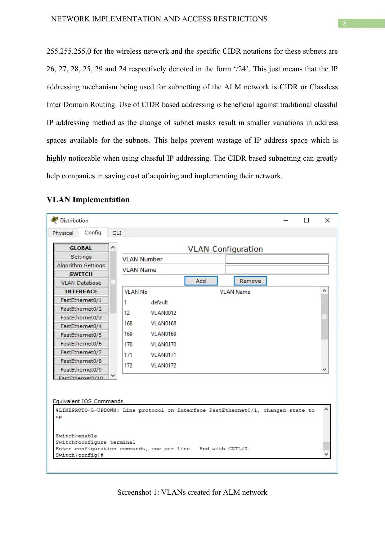
VLAN Implementation
Screenshot 1: VLANs created for ALM network
⊘ This is a preview!⊘
Do you want full access?
Subscribe today to unlock all pages.
Trusted by 1+ million students worldwide
9
NETWORK IMPLEMENTATION AND ACCESS RESTRICTIONS
The screenshot above shows the number of VLANs that have been created for the network
along with VLAN 1 which is present by default. All these VLANs are added in the multilayer
switch which connects with the router as well as with other lower layer switches through the
various interfaces in trunk mode. The IP subnetting for the different VLAN segments along
with the automatic IP allocation of devices in these departments are configured in the main
router as the DHCP pools created are mapped with the respective VLANs. This enables the
devices of one VLAN like the workstations and printers access other devices of a different
VLAN like the different servers as well as the smartphones connected through the wireless
network. The lower layer switches connect the individual devices through their specific
VLANs via interfaces in access mode. This means the devices within each department can
communicate with one another. The different VLANs created in the network according to
their numbers are 12 for wireless, 168 for Dept. 1, 169 for Dept. 2, 170 for Dept. 3, 171 for
Dept. 4 and 172 for the servers.
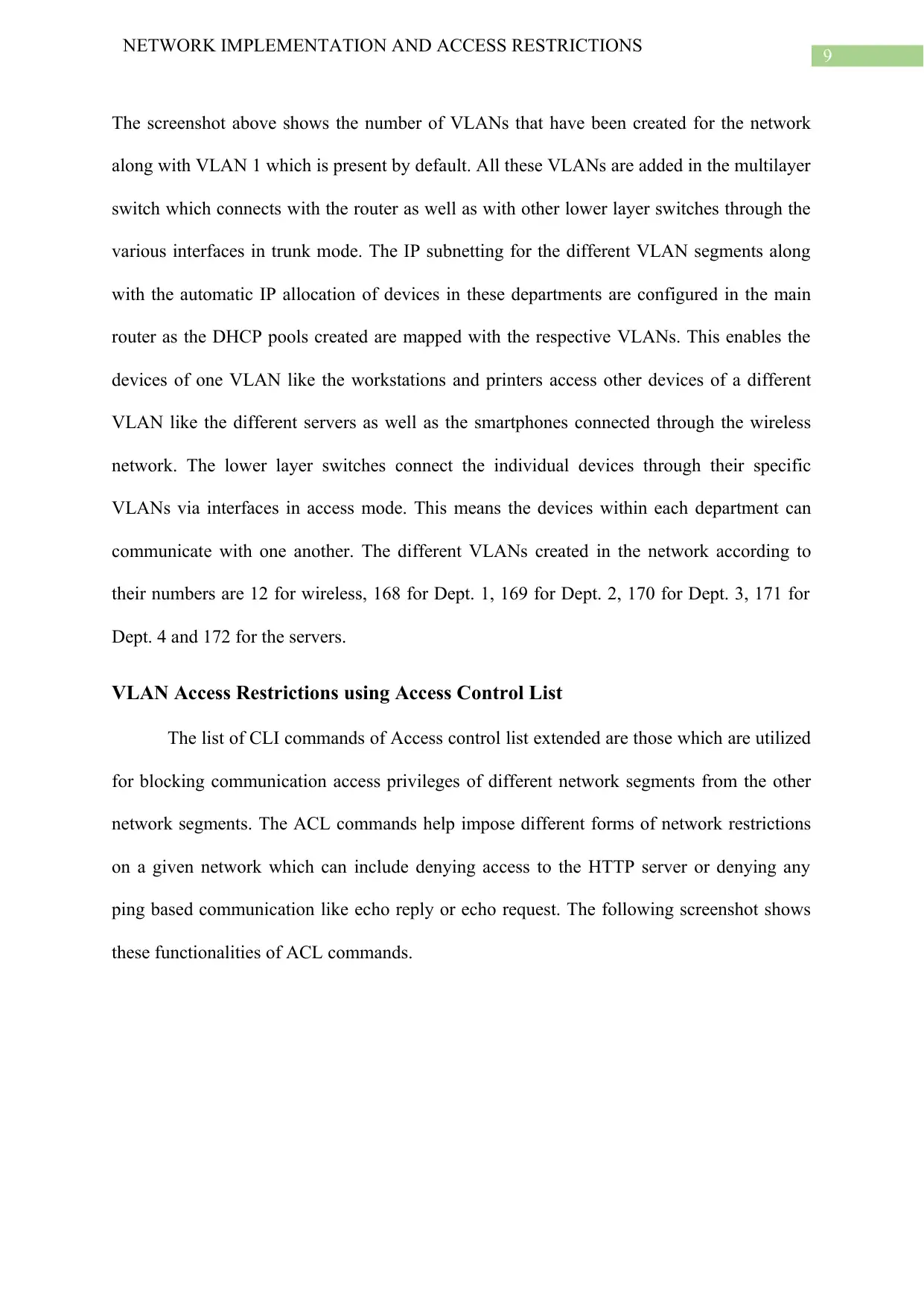
VLAN Access Restrictions using Access Control List
The list of CLI commands of Access control list extended are those which are utilized
for blocking communication access privileges of different network segments from the other
network segments. The ACL commands help impose different forms of network restrictions
on a given network which can include denying access to the HTTP server or denying any
ping based communication like echo reply or echo request. The following screenshot shows
these functionalities of ACL commands.
NETWORK IMPLEMENTATION AND ACCESS RESTRICTIONS
The screenshot above shows the number of VLANs that have been created for the network
along with VLAN 1 which is present by default. All these VLANs are added in the multilayer
switch which connects with the router as well as with other lower layer switches through the
various interfaces in trunk mode. The IP subnetting for the different VLAN segments along
with the automatic IP allocation of devices in these departments are configured in the main
router as the DHCP pools created are mapped with the respective VLANs. This enables the
devices of one VLAN like the workstations and printers access other devices of a different
VLAN like the different servers as well as the smartphones connected through the wireless
network. The lower layer switches connect the individual devices through their specific
VLANs via interfaces in access mode. This means the devices within each department can
communicate with one another. The different VLANs created in the network according to
their numbers are 12 for wireless, 168 for Dept. 1, 169 for Dept. 2, 170 for Dept. 3, 171 for
Dept. 4 and 172 for the servers.
VLAN Access Restrictions using Access Control List
The list of CLI commands of Access control list extended are those which are utilized
for blocking communication access privileges of different network segments from the other
network segments. The ACL commands help impose different forms of network restrictions
on a given network which can include denying access to the HTTP server or denying any
ping based communication like echo reply or echo request. The following screenshot shows
these functionalities of ACL commands.
Paraphrase This Document
Need a fresh take? Get an instant paraphrase of this document with our AI Paraphraser
10
NETWORK IMPLEMENTATION AND ACCESS RESTRICTIONS
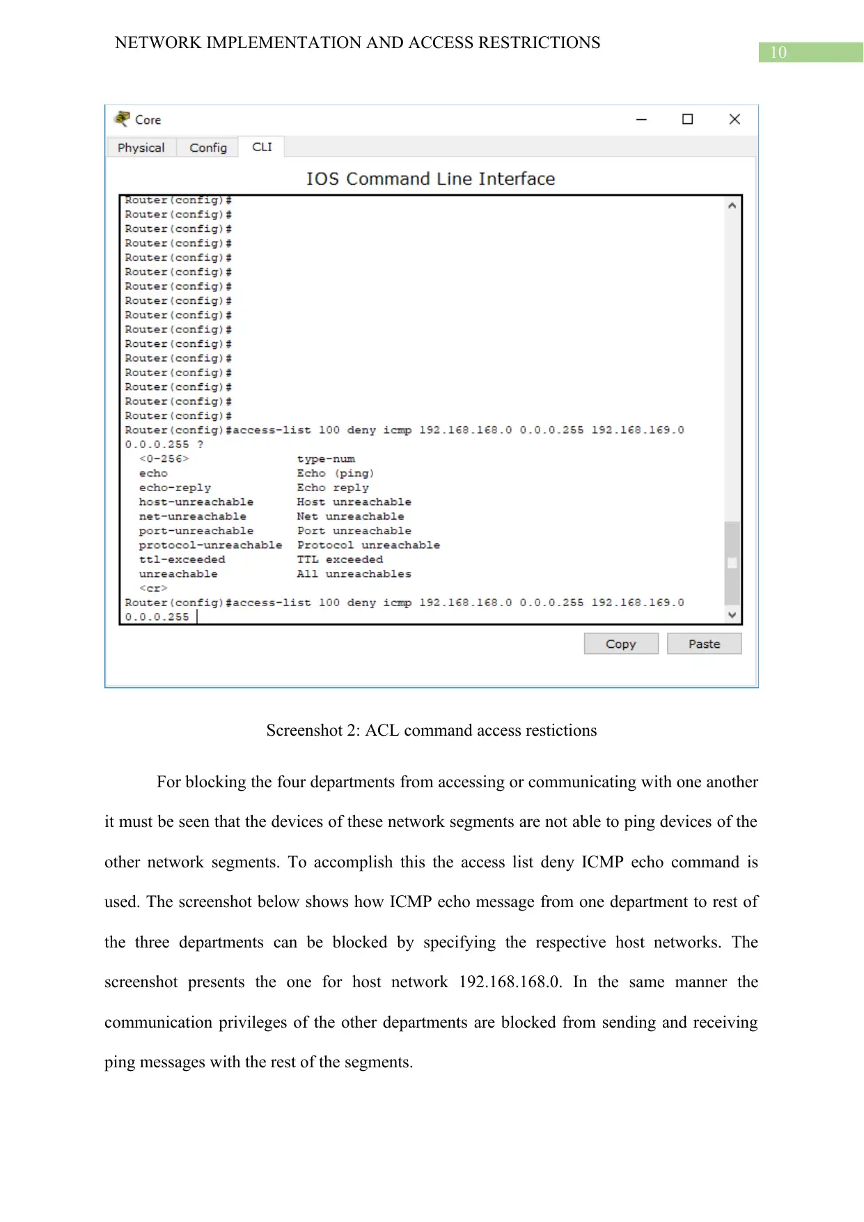
Screenshot 2: ACL command access restictions
For blocking the four departments from accessing or communicating with one another
it must be seen that the devices of these network segments are not able to ping devices of the
other network segments. To accomplish this the access list deny ICMP echo command is
used. The screenshot below shows how ICMP echo message from one department to rest of
the three departments can be blocked by specifying the respective host networks. The
screenshot presents the one for host network 192.168.168.0. In the same manner the
communication privileges of the other departments are blocked from sending and receiving
ping messages with the rest of the segments.
NETWORK IMPLEMENTATION AND ACCESS RESTRICTIONS
Screenshot 2: ACL command access restictions
For blocking the four departments from accessing or communicating with one another
it must be seen that the devices of these network segments are not able to ping devices of the
other network segments. To accomplish this the access list deny ICMP echo command is
used. The screenshot below shows how ICMP echo message from one department to rest of
the three departments can be blocked by specifying the respective host networks. The
screenshot presents the one for host network 192.168.168.0. In the same manner the
communication privileges of the other departments are blocked from sending and receiving
ping messages with the rest of the segments.
11
NETWORK IMPLEMENTATION AND ACCESS RESTRICTIONS
Screenshot 3: ACL commands for restricting host 192.168.168.0
Validation and Tests
For checking whether this proposed network is appropriate for the company
alm.co.uk, it is required to check if indeed the requirements for the network specified earlier
is being fulfilled by the network. This is why validation checks are performed to check
whether the different network segment are actually prohibited from sending or receiving ping
messages from one another, whether the devices of the different departments are able to send
or receive ping messages from the server or if the devices can access the smartphones
accessing the wireless network.
⊘ This is a preview!⊘
Do you want full access?
Subscribe today to unlock all pages.
Trusted by 1+ million students worldwide
1 out of 20
Related Documents


Your All-in-One AI-Powered Toolkit for Academic Success.
+13062052269
info@desklib.com
Available 24*7 on WhatsApp / Email
![[object Object]](/_next/static/media/star-bottom.7253800d.svg)
Unlock your academic potential
Copyright © 2020–2026 A2Z Services. All Rights Reserved. Developed and managed by ZUCOL.