Network Design and Troubleshooting: Case Study ALM Network Report
VerifiedAdded on 2022/11/13
|19
|3379
|480
Report
AI Summary
This report details the design and implementation of a network for alm.co.uk, addressing specific requirements for four departments and four servers (web, email, DNS, and file). The report begins with a requirements summary, followed by a network design diagram created in Cisco Packet Tracer, describing network configuration and device connections. It then explores subnetting, VLAN usage, and network segment restrictions using access control lists. The report validates the network design through testing and validation, demonstrating the successful restriction of inter-departmental access while ensuring server accessibility for all users. Protocols for device connectivity and IP address assignments are also discussed, concluding with key observations about the network design and its effectiveness in meeting the specified requirements.

Running head: NETWORK SECURITY AND DESIGN
Network Security and Design
Name of the Student
Name of the University
Author Note
Network Security and Design
Name of the Student
Name of the University
Author Note
Paraphrase This Document
Need a fresh take? Get an instant paraphrase of this document with our AI Paraphraser
1NETWORK SECURITY AND DESIGN
Summary
Designing networks and configuring them plays a critical part in ensuring how effective and
efficient the network implementation can be in companies. The report proposes a configured
network design for the business alm.co.uk and attempts to meet the requirements of the
network. First the report presents a summary of these requirements put forward by ALM
where details regarding the arrangement and count of the devices based on the specific
departments that are to be served by the network are given. The report then presents the
network design with the help of a network design diagram created in cisco packet tracer and
duly describes the network, the configuration and how the network equipment connects the
devices. Then the report jumps to the subnetting section where the different subnets created
for the different network segments and their respective details such as size requirement,
allocated address space, network and broadcast address, subnet masks CIDR and IP ranges
are mentioned in a tabular format and discussed thereafter. The report then explains how the
VLANs are used in the network by showing all the VLANs created in the network and how
access can be made from one VLAN to another. However the network is to ensure that none
of the four departments are able to access the other departments and hence appropriate access
control list command are used. The report shows the types of access control list commands
that can be used and mentions the one used by the proposed network to impose the required
restrictions. Next the report carries out tests and validates whether the network meets the
different requirements of alm.co.uk and proves the tests a success with the help of
screenshots. Then after talking about the protocols used for network connectivity and
assigning IP addresses to the devices the report ends with conclusions.
2NETWORK SECURITY AND DESIGN
Table of Contents
Introduction................................................................................................................................3
Network Proposal.......................................................................................................................4
Requirements Summary.........................................................................................................4
Network Design.....................................................................................................................5
Subnetting of the network......................................................................................................6
Use of VLANs........................................................................................................................8
Network Segment Restrictions using Access Control List....................................................9
Testing and Validation.........................................................................................................11
Protocols for connecting devices.........................................................................................13
Conclusion................................................................................................................................14
Bibliography.............................................................................................................................16
⊘ This is a preview!⊘
Do you want full access?
Subscribe today to unlock all pages.
Trusted by 1+ million students worldwide
3NETWORK SECURITY AND DESIGN
Introduction
The impact designing of networks and their configuration have on effectiveness and
efficiency of networks is evident today and hence the report attempts to propose a configured
network design for the business alm.co.uk as per requirements. The report begins by
presenting a summary of these requirements put forward by ALM where details regarding the
arrangement and count of the devices based on the specific departments that are to be served
by the network are given. The report then presents the network design with the help of a
network design diagram created in cisco packet tracer and duly describes the network, the
configuration and how the network equipment connects the devices. Then the report jumps to
the subnetting section where the different subnets created for the different network segments
and their respective details such as size requirement, allocated address space, network and
broadcast address, subnet masks CIDR and IP ranges are mentioned in a tabular format and
discussed thereafter. The report then explains how the VLANs are used in the network by
showing all the VLANs created in the network and how access can be made from one VLAN
to another. However the network is to ensure that none of the four departments are able to
access the other departments and hence appropriate access control list command are used.
The report shows the types of access control list commands that can be used and mentions the
one used by the proposed network to impose the required restrictions. Next the report carries
out tests and validates whether the network meets the different requirements of alm.co.uk and
proves the tests a success with the help of screenshots. Then after talking about the protocols
used for network connectivity and assigning IP addresses to the devices the report ends with
observations in the concluding notes.
Paraphrase This Document
Need a fresh take? Get an instant paraphrase of this document with our AI Paraphraser
4NETWORK SECURITY AND DESIGN
Network Proposal
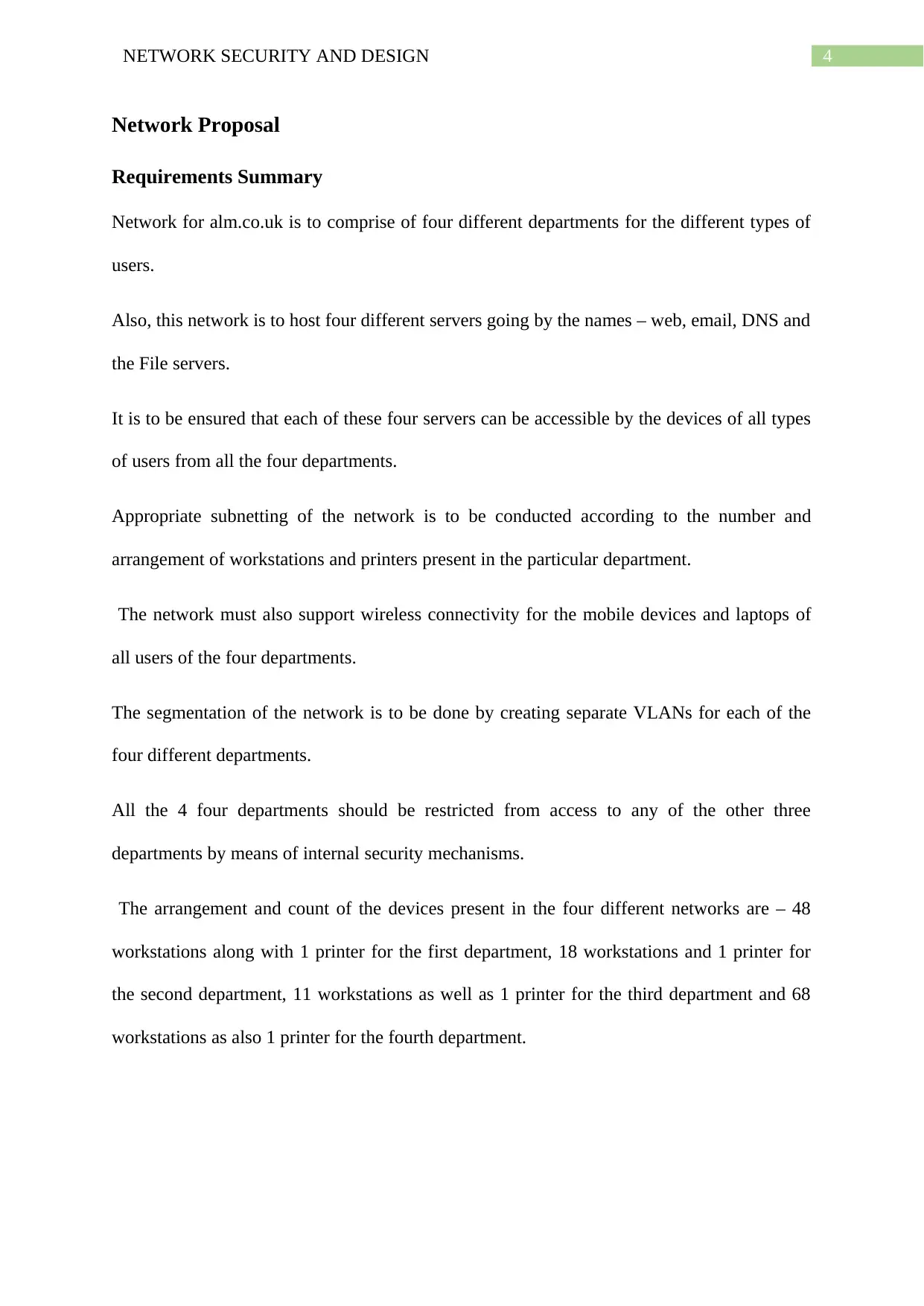
Requirements Summary
Network for alm.co.uk is to comprise of four different departments for the different types of
users.
Also, this network is to host four different servers going by the names – web, email, DNS and
the File servers.
It is to be ensured that each of these four servers can be accessible by the devices of all types
of users from all the four departments.
Appropriate subnetting of the network is to be conducted according to the number and
arrangement of workstations and printers present in the particular department.
The network must also support wireless connectivity for the mobile devices and laptops of
all users of the four departments.
The segmentation of the network is to be done by creating separate VLANs for each of the
four different departments.
All the 4 four departments should be restricted from access to any of the other three
departments by means of internal security mechanisms.
The arrangement and count of the devices present in the four different networks are – 48
workstations along with 1 printer for the first department, 18 workstations and 1 printer for
the second department, 11 workstations as well as 1 printer for the third department and 68
workstations as also 1 printer for the fourth department.
Network Proposal
Requirements Summary
Network for alm.co.uk is to comprise of four different departments for the different types of
users.
Also, this network is to host four different servers going by the names – web, email, DNS and
the File servers.
It is to be ensured that each of these four servers can be accessible by the devices of all types
of users from all the four departments.
Appropriate subnetting of the network is to be conducted according to the number and
arrangement of workstations and printers present in the particular department.
The network must also support wireless connectivity for the mobile devices and laptops of
all users of the four departments.
The segmentation of the network is to be done by creating separate VLANs for each of the
four different departments.
All the 4 four departments should be restricted from access to any of the other three
departments by means of internal security mechanisms.
The arrangement and count of the devices present in the four different networks are – 48
workstations along with 1 printer for the first department, 18 workstations and 1 printer for
the second department, 11 workstations as well as 1 printer for the third department and 68
workstations as also 1 printer for the fourth department.
5NETWORK SECURITY AND DESIGN
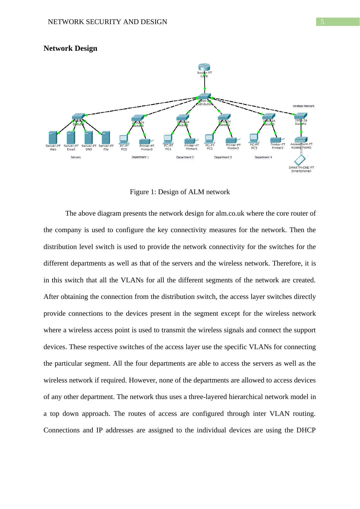
Network Design
Figure 1: Design of ALM network
The above diagram presents the network design for alm.co.uk where the core router of
the company is used to configure the key connectivity measures for the network. Then the
distribution level switch is used to provide the network connectivity for the switches for the
different departments as well as that of the servers and the wireless network. Therefore, it is
in this switch that all the VLANs for all the different segments of the network are created.
After obtaining the connection from the distribution switch, the access layer switches directly
provide connections to the devices present in the segment except for the wireless network
where a wireless access point is used to transmit the wireless signals and connect the support
devices. These respective switches of the access layer use the specific VLANs for connecting
the particular segment. All the four departments are able to access the servers as well as the
wireless network if required. However, none of the departments are allowed to access devices
of any other department. The network thus uses a three-layered hierarchical network model in
a top down approach. The routes of access are configured through inter VLAN routing.
Connections and IP addresses are assigned to the individual devices are using the DHCP
⊘ This is a preview!⊘
Do you want full access?
Subscribe today to unlock all pages.
Trusted by 1+ million students worldwide
6NETWORK SECURITY AND DESIGN
protocol. Access between one department and another is restricted with the help of access
control list commands.
Subnetting of the network
Name
of
Subnet
s
Requi
red
Sizes
Sizes
of
Alloca
tion
Network
Address
es
CI
DR
Subnet
Masks
Assignabl
e IP
Ranges
Broadcast
Addresse
s
First
Depart
ment
49 62
192.168.
168.0
/26
255.255.2
55.192
192.168.1
68.1 -
192.168.1
68.62
192.168.1
68.63
Second
Depart
ment
19 30
192.168.
169.0
/27
255.255.2
55.224
192.168.1
69.1 -
192.168.1
69.30
192.168.1
69.31
Third
Depart
ment
12 14
192.168.
170.0
/28
255.255.2
55.240
192.168.1
70.1 -
192.168.1
70.14
192.168.1
70.15
Fourth
Depart
ment 4
69 126
192.168.
171.0
/25
255.255.2
55.128
192.168.1
71.1 -
192.168.1
71.126
192.168.1
71.127
Subnet
for
4 6 192.168. /29 255.255.2 192.168.1
72.1 -
192.168.1
Paraphrase This Document
Need a fresh take? Get an instant paraphrase of this document with our AI Paraphraser
7NETWORK SECURITY AND DESIGN
Servers 172.0 55.248
192.168.1
72.6
72.7
Subnet
for
Wireles
s
Networ
k
250 254
10.11.12.
0
/24
255.255.2
55.0
10.11.12.1
-
10.11.12.2
54
10.11.12.2
55
The subnetting used for the network of alm.co.uk is provided in the above table.
Different subnets are created for the four different as well as for the servers and the wireless
network. IP networks addresses 192.168.X.0 are used for the segments that deal with
providing wired access to devices where X refers to the changing octet of the subnets and the
network address 10.11.12.0 is used for providing wireless connectivity to supported devices.
Since the access routes are configured through inter VLAN routing the third octet of the
different subnets required to be different. Hence the different subnets for the different
segments of the network are 192.168.168.0, 192.168.169.0, 192.168.170.0, 192.168.171,
192.168.172 and 10.11.12.0 for the first department, second department, third department,
fourth department, the servers and the wireless network respectively. The subnet masks for
these different subnets are 255.255.255.192, 255.255.255.224, 255.255.255.240,
255.255.255.128, 255.255.255.248 and 255.255.255.0 while the corresponding CIDR values
are /26, /27, /28, /25, /29 and /24 respectively. As can be noticed, the IP addressing scheme
used here is CIDR or classless interdomain routing. This is because of the immense benefit it
brings to businesses by ensuring that least allocated address space is wasted. CIDR addresses
the issue of wastage of allocated address space offering make incremental transitions when
8NETWORK SECURITY AND DESIGN
creating subnets and as a result has become the preferred IP addressing scheme by replacing
the inefficient classful addressing scheme.
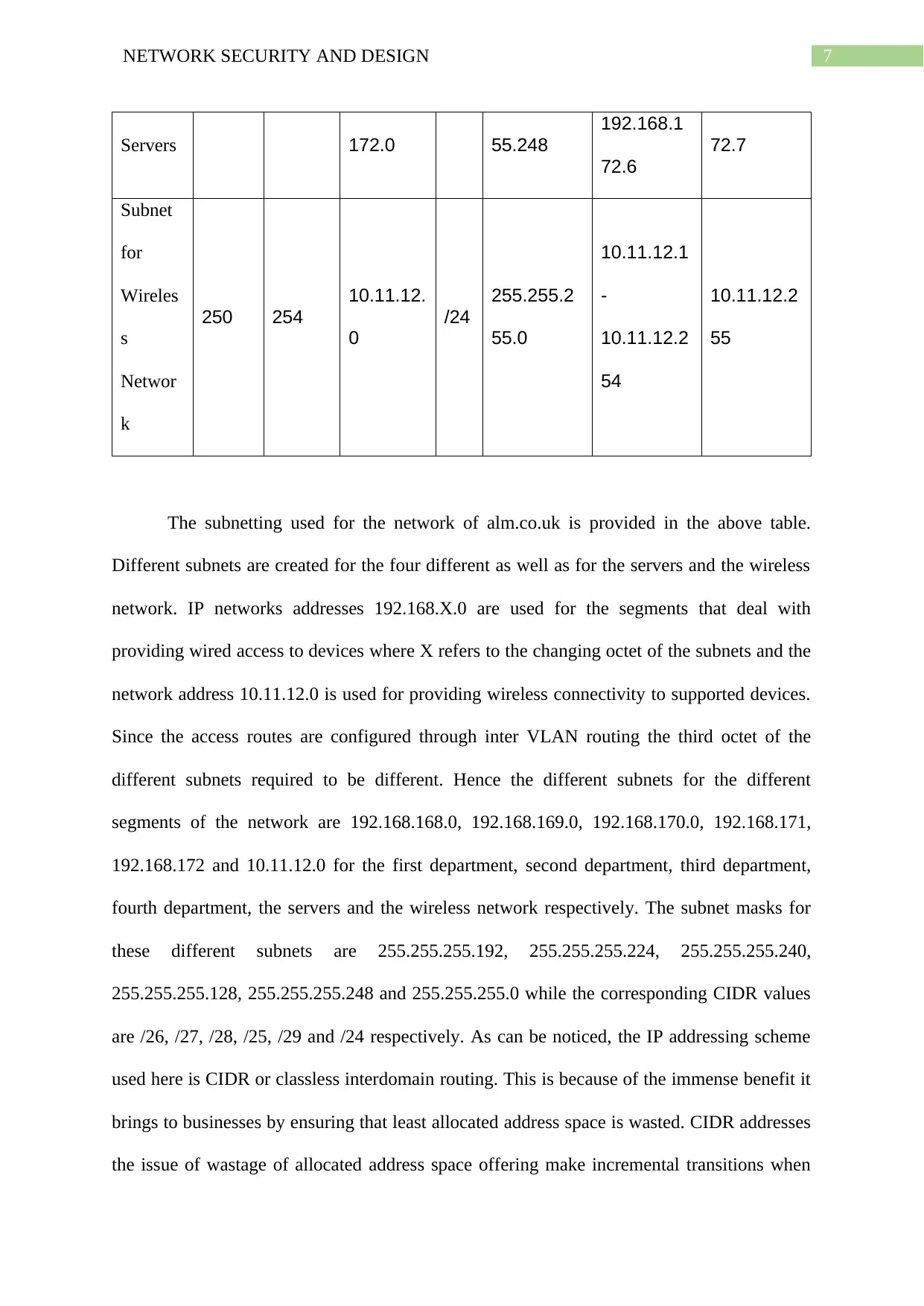
Use of VLANs
Figure 2: Different VLANs for segmentation of AML network
The above screenshot shows the different VLANs that have been created for the
various segments of the network of alm.co.uk. These are the VLANs with VLAN No. 12,
168, 169,170, 171 and 172. If looked carefully these are the same numbers found in the third
octet of the different subnets. For the routes of access to be configured through inter VLAN
routing, it is essential that the VLAN number matches the third octet of the subnets. The
creating subnets and as a result has become the preferred IP addressing scheme by replacing
the inefficient classful addressing scheme.
Use of VLANs
Figure 2: Different VLANs for segmentation of AML network
The above screenshot shows the different VLANs that have been created for the
various segments of the network of alm.co.uk. These are the VLANs with VLAN No. 12,
168, 169,170, 171 and 172. If looked carefully these are the same numbers found in the third
octet of the different subnets. For the routes of access to be configured through inter VLAN
routing, it is essential that the VLAN number matches the third octet of the subnets. The
⊘ This is a preview!⊘
Do you want full access?
Subscribe today to unlock all pages.
Trusted by 1+ million students worldwide
9NETWORK SECURITY AND DESIGN
distribution layer switch is connected to the router as well as the switches of the access layer
in switchport mode trunk. The lower layer switches connect the individual devices or the
wireless access point through switchport mode access.
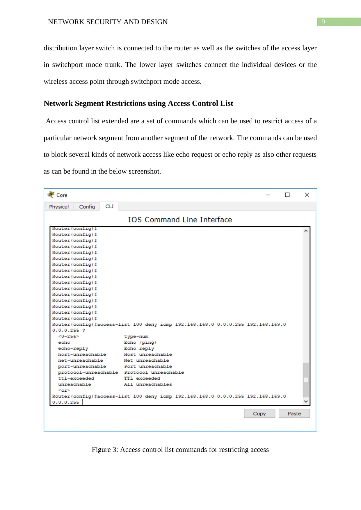
Network Segment Restrictions using Access Control List
Access control list extended are a set of commands which can be used to restrict access of a
particular network segment from another segment of the network. The commands can be used
to block several kinds of network access like echo request or echo reply as also other requests
as can be found in the below screenshot.
Figure 3: Access control list commands for restricting access
distribution layer switch is connected to the router as well as the switches of the access layer
in switchport mode trunk. The lower layer switches connect the individual devices or the
wireless access point through switchport mode access.
Network Segment Restrictions using Access Control List
Access control list extended are a set of commands which can be used to restrict access of a
particular network segment from another segment of the network. The commands can be used
to block several kinds of network access like echo request or echo reply as also other requests
as can be found in the below screenshot.
Figure 3: Access control list commands for restricting access
Paraphrase This Document
Need a fresh take? Get an instant paraphrase of this document with our AI Paraphraser
10NETWORK SECURITY AND DESIGN
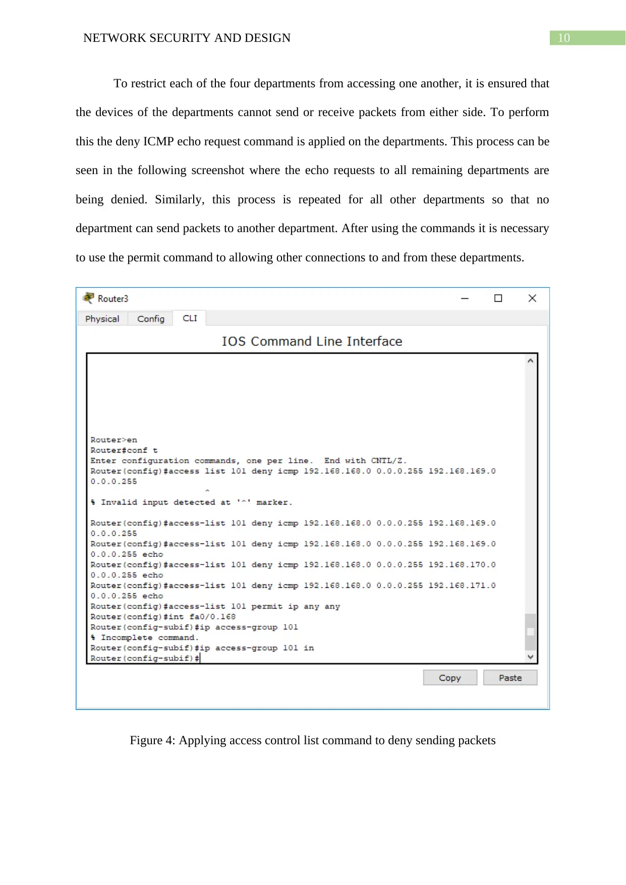
To restrict each of the four departments from accessing one another, it is ensured that
the devices of the departments cannot send or receive packets from either side. To perform
this the deny ICMP echo request command is applied on the departments. This process can be
seen in the following screenshot where the echo requests to all remaining departments are
being denied. Similarly, this process is repeated for all other departments so that no
department can send packets to another department. After using the commands it is necessary
to use the permit command to allowing other connections to and from these departments.
Figure 4: Applying access control list command to deny sending packets
11NETWORK SECURITY AND DESIGN
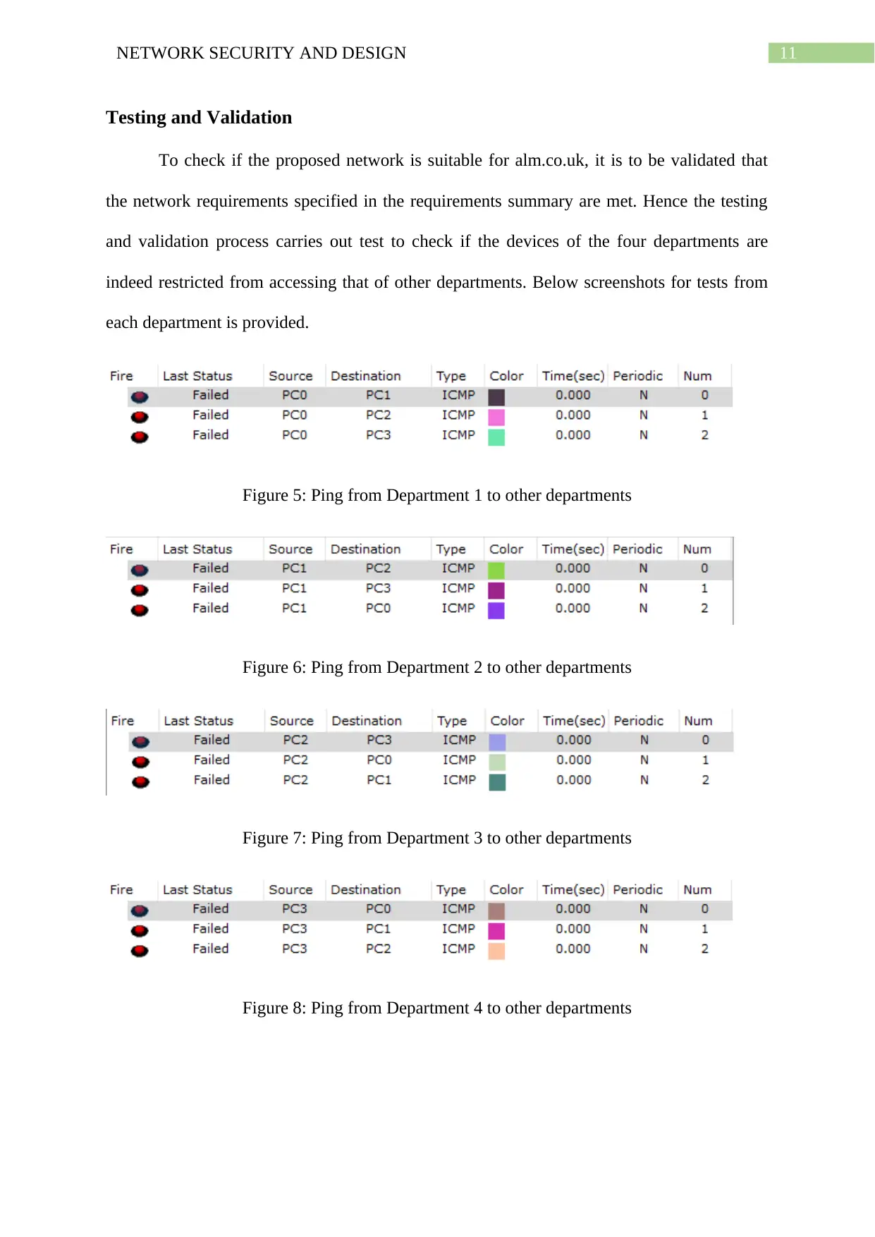
Testing and Validation
To check if the proposed network is suitable for alm.co.uk, it is to be validated that
the network requirements specified in the requirements summary are met. Hence the testing
and validation process carries out test to check if the devices of the four departments are
indeed restricted from accessing that of other departments. Below screenshots for tests from
each department is provided.
Figure 5: Ping from Department 1 to other departments
Figure 6: Ping from Department 2 to other departments
Figure 7: Ping from Department 3 to other departments
Figure 8: Ping from Department 4 to other departments
⊘ This is a preview!⊘
Do you want full access?
Subscribe today to unlock all pages.
Trusted by 1+ million students worldwide
1 out of 19
Related Documents


Your All-in-One AI-Powered Toolkit for Academic Success.
+13062052269
info@desklib.com
Available 24*7 on WhatsApp / Email
![[object Object]](/_next/static/media/star-bottom.7253800d.svg)
Unlock your academic potential
Copyright © 2020–2026 A2Z Services. All Rights Reserved. Developed and managed by ZUCOL.