CN5122 - Network Design and Analysis with Cisco Packet Tracer
VerifiedAdded on 2023/04/07
|55
|7231
|108
Practical Assignment
AI Summary
This assignment focuses on network analysis and design using Cisco Packet Tracer, covering essential concepts such as IP addressing, subnetting, and network topologies. It details how to determine network IP addresses, IP masks, and subnetting for given IP addresses, including calculations for net-mask length, network address, and broadcast address. The assignment also discusses the types of cables used for network connections, such as twisted pair and crossover cables, and their respective applications. Furthermore, it demonstrates network design and configuration of the IP protocol within the Cisco Packet Tracer environment, highlighting security systems and device configurations. The document is contributed by a student and available on Desklib, a platform offering various study tools for students.
TITLE: Networking Analysis and Design Using Cisco Packet Tracer
Networking Analysis and Design Using Cisco Packet Tracer
Student’s ID: 1705253
Student’s ID: 1604308
Networking Analysis and Design Using Cisco Packet Tracer
Student’s ID: 1705253
Student’s ID: 1604308
Paraphrase This Document
Need a fresh take? Get an instant paraphrase of this document with our AI Paraphraser
i
Executive Summary
Computer network can be analyzed and designed using Cisco Packet Tracer. Network operates
using by connecting the computers and its peripherals within that network using switches and
routers as the main devices. This two devices allows perfect and simplified communications within
that network. Routers and switches may look similar but there functions greatly differ from each
other. Switch connects devices such computers, printers, servers by creating the sharing resource to
all those devices. It allows communication and sharing of information's between such devices in
that network. Cisco Packet Tracer is the a tool that can be used practical to do designing and
analysis before the final physical configuration and installations. A logical topology is the criteria
or the structure that is used to connect all the devices within a network. Logical topology is a
connection where the node is used as the main structure. Logical topology can also refers to signal
topology of a network. This is defined as how signals passes through a physical network. The set up
and transmissions of the signals in that network is restricted within the network protocols. The
connections of this devices can be in several types of topology such as star, ring among other
topology.
ii
TABLE OF CONTENTS
Page
TITLE................................................................................................................…………... ……..i
EXECUTIVE SUMMARY ....................................................................................................…..ii
TABLE OF CONTENTS .............................................................................................………….iii
INTRODUCTION ........................................................................................................................ iv
OBJECTIVES AND OVERVIEW ........................................................................................…...v
CHAPTER
Student ID: 1705253
How we can determine Network IP Address, IP Mask, and Sub-netting
for the given IP Address. ......................................................................................…………1
Cables used for connection ................................................................................…………..4
Configure Logical Topology………………………………………………………………5
Demonstration of network design and configuration of the IP protocol in
Cisco packer tracer……………………………………………………………………….17
Student ID: 1705253
How we can determine Network IP Address, IP Mask, and Sub-netting
for the given IP Address. ......................................................................................……….18
Cables used for connection ................................................................................………...21
Configure Logical Topology……………………………………………………………..22
Demonstration of network design and configuration of the IP protocol in
Cisco packer tracer……………………………………………………………………….37
⊘ This is a preview!⊘
Do you want full access?
Subscribe today to unlock all pages.
Trusted by 1+ million students worldwide
SECURITY SYSTEMS ON THE BOTH ROUTERS AND ALL OTHER ACTIVE DEVICES..33
CONFIGURE ALL DEVICES INCLUDING THE ROUTERS AND SWITCHES……………..38
CONCLUSION…………………………………………………………………………………40
REFERENCES ...............................................................................................................…….. .41
iii
Introduction
Computer network can be analyzed and designed using Cisco Packet Tracer. Network operates
using by connecting the computers and its peripherals within that network using switches and
routers as the main devices. This two devices allows perfect and simplified communications within
that network. Routers and switches may look similar but there functions greatly differ from each
other. Switch connects devices such computers, printers, servers by creating the sharing resource to
all those devices. It allows communication and sharing of information's between such devices in
that network. Cisco Packet Tracer is the a tool that can be used practical to do designing and
analysis before the final physical configuration and installations. A logical topology is the criteria
or the structure that is used to connect all the devices within a network. Logical topology is a
connection where the node is used as the main structure (Kreutz, Ramos, Verissimo, Rothenberg,
Azodolmolky & Uhlig, 2015). Logical topology can also refers to signal topology of a network.
This is defined as how signals passes through a physical network. The set up and transmissions of
the signals in that network is restricted within the network protocols. The connections of this
devices can be in several types of topology such as star, ring among other topology.
Paraphrase This Document
Need a fresh take? Get an instant paraphrase of this document with our AI Paraphraser
iv
Objectives and overview of the course work
Network operates by connecting the computers and its peripherals within that network using
switches and routers as the main devices. This two devices allows perfect and simplified
communications within that network. Routers and switches may look similar but there functions
greatly differ from each other. Switch connects devices such computers, printers, servers by creating
the sharing resource to all those devices. It allows communication and sharing of information's
between such devices in that network. Unmanaged switch works outside the box and it doesn't
allow any changes to be made. Home network mainly uses such kind of switches. Managed switch
will always allow you to access and manage the switch. It allows great accessibility and flexibility
to monitor and adjust the traffic flow within the Network (Johannisson, 2017).
Sub-netting is process of utilizing larger networks by dividing them into smaller sub-networks
known as sub-nets. IP address is always used to to identify the sub-net and for broadcasting also
within the sub-net. Smaller networks create smaller broadcast domains therefore less network
broadcast traffic is experienced in the boundaries. Isolation of network by trouble-shouting will
simplify large networks when braked into smaller networks (Keeble, & Wilkinson, 2017).
IP address in classless has no relationship between the the value of byte of the specific address and
number of bits in that network. A different method can be used to calculate the network size in that
IP address. It allows borrowing of the bits that are normally used to extend the network portion. A
router can manipulate binary numbers where 1 is used to identify bit in IP address for that network
and 0 to identify bit in that host addresses used (Xia, Wen, Foh, Niyato, & Xie, 2015).
v
Student ID: 1705253
How we can determine Network IP Address, IP Mask, and Sub-netting for the given IP
Address.
The most common IP versions used today are IPv4 and IPv6. IPv4 is stilled used today despite the
availability of the upgrade IPv6. Its 32-bit binary numbers which contains 2 sub-addresses. Internet
and other networks corporate uses IPv4 since it allows 232 addresses which is still useful.
Limitation was mainly lack of enough unique addresses for all the devices in the network. IPv6 is
an upgrade which contains increase number of addresses space and allow 2128 addresses. It's also
improved in terms of IP packet headers efficiency and also routing and security (Comer, 2018) .
IP addresses are design mainly to work over a dynamic network. This implies that IP should only
work without a central directory or monitor which cannot on certain links. IP address is a
connectionless protocol which contains source IP address, destination IP address. The error is
always handled in the upper level protocol instead such as TCP (Oberst, Wegmann, Stodt, Brand, &
Chamarro, 2017).
In both IPv4 and IPv6, its very hard to remember IP address inn every devices attached to them
except on smallest networks. Name resolution technique gives a way much simpler to identify IP
address. This name resolution is handled by the Domain Name System (DNS). A name can be used
in place of the destination IP address. IP address is used for making communications when the
request is initiated (Wang, Carver, Phelan, Sanchez, Garg, Peng, & Porto, 2016).
⊘ This is a preview!⊘
Do you want full access?
Subscribe today to unlock all pages.
Trusted by 1+ million students worldwide
Sub-netting is process of utilizing larger networks by dividing them into smaller sub-networks
known as sub-nets. IP address is always used to to identify the sub-net and for broadcasting also
within the sub-net. Smaller networks create smaller broadcast domains therefore less network
broadcast traffic is experienced in the boundaries. Isolation of network by trouble-shouting will
simplify large networks when braked into smaller networks (Hwang, Ramakrishnan, & Wood,
2015).
IP address in classless has no relationship between the the value of byte of the specific address and
number of bits in that network. A different method can be used to measure the network size in that
portion of the IP address. It allows borrowing of the bits that are normally used to extend the
network portion. A router can manipulate binary numbers where 1 is used to identify bit in IP
address for that network and 0 to identify bit in that host addresses used (Blenk, Basta, Reisslein,
Kellerer, 2016).
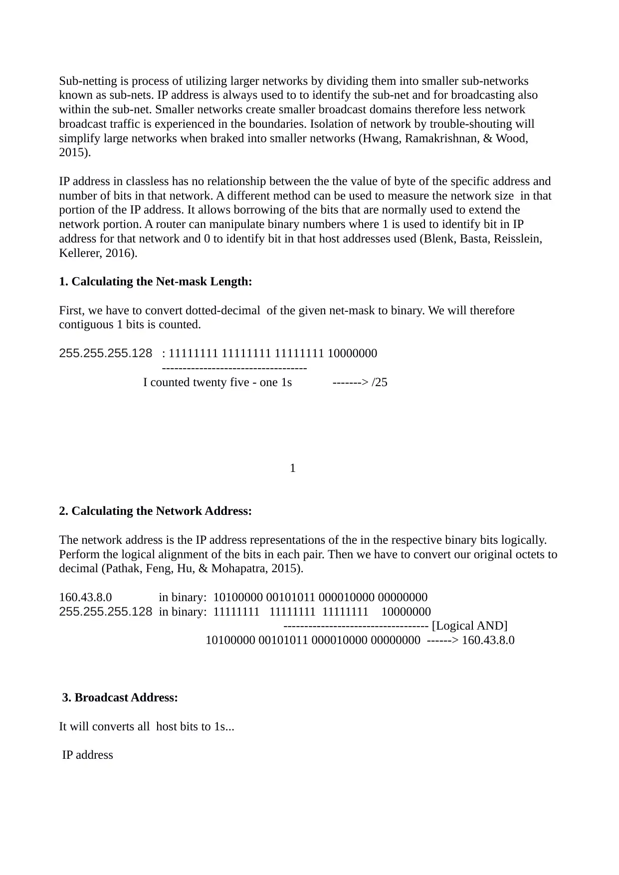
1. Calculating the Net-mask Length:
First, we have to convert dotted-decimal of the given net-mask to binary. We will therefore
contiguous 1 bits is counted.
255.255.255.128 : 11111111 11111111 11111111 10000000
-----------------------------------
I counted twenty five - one 1s -------> /25
1
2. Calculating the Network Address:
The network address is the IP address representations of the in the respective binary bits logically.
Perform the logical alignment of the bits in each pair. Then we have to convert our original octets to
decimal (Pathak, Feng, Hu, & Mohapatra, 2015).
160.43.8.0 in binary: 10100000 00101011 000010000 00000000
255.255.255.128 in binary: 11111111 11111111 11111111 10000000
----------------------------------- [Logical AND]
10100000 00101011 000010000 00000000 ------> 160.43.8.0
3. Broadcast Address:
It will converts all host bits to 1s...
IP address
known as sub-nets. IP address is always used to to identify the sub-net and for broadcasting also
within the sub-net. Smaller networks create smaller broadcast domains therefore less network
broadcast traffic is experienced in the boundaries. Isolation of network by trouble-shouting will
simplify large networks when braked into smaller networks (Hwang, Ramakrishnan, & Wood,
2015).
IP address in classless has no relationship between the the value of byte of the specific address and
number of bits in that network. A different method can be used to measure the network size in that
portion of the IP address. It allows borrowing of the bits that are normally used to extend the
network portion. A router can manipulate binary numbers where 1 is used to identify bit in IP
address for that network and 0 to identify bit in that host addresses used (Blenk, Basta, Reisslein,
Kellerer, 2016).
1. Calculating the Net-mask Length:
First, we have to convert dotted-decimal of the given net-mask to binary. We will therefore
contiguous 1 bits is counted.
255.255.255.128 : 11111111 11111111 11111111 10000000
-----------------------------------
I counted twenty five - one 1s -------> /25
1
2. Calculating the Network Address:
The network address is the IP address representations of the in the respective binary bits logically.
Perform the logical alignment of the bits in each pair. Then we have to convert our original octets to
decimal (Pathak, Feng, Hu, & Mohapatra, 2015).
160.43.8.0 in binary: 10100000 00101011 000010000 00000000
255.255.255.128 in binary: 11111111 11111111 11111111 10000000
----------------------------------- [Logical AND]
10100000 00101011 000010000 00000000 ------> 160.43.8.0
3. Broadcast Address:
It will converts all host bits to 1s...
IP address
Paraphrase This Document
Need a fresh take? Get an instant paraphrase of this document with our AI Paraphraser
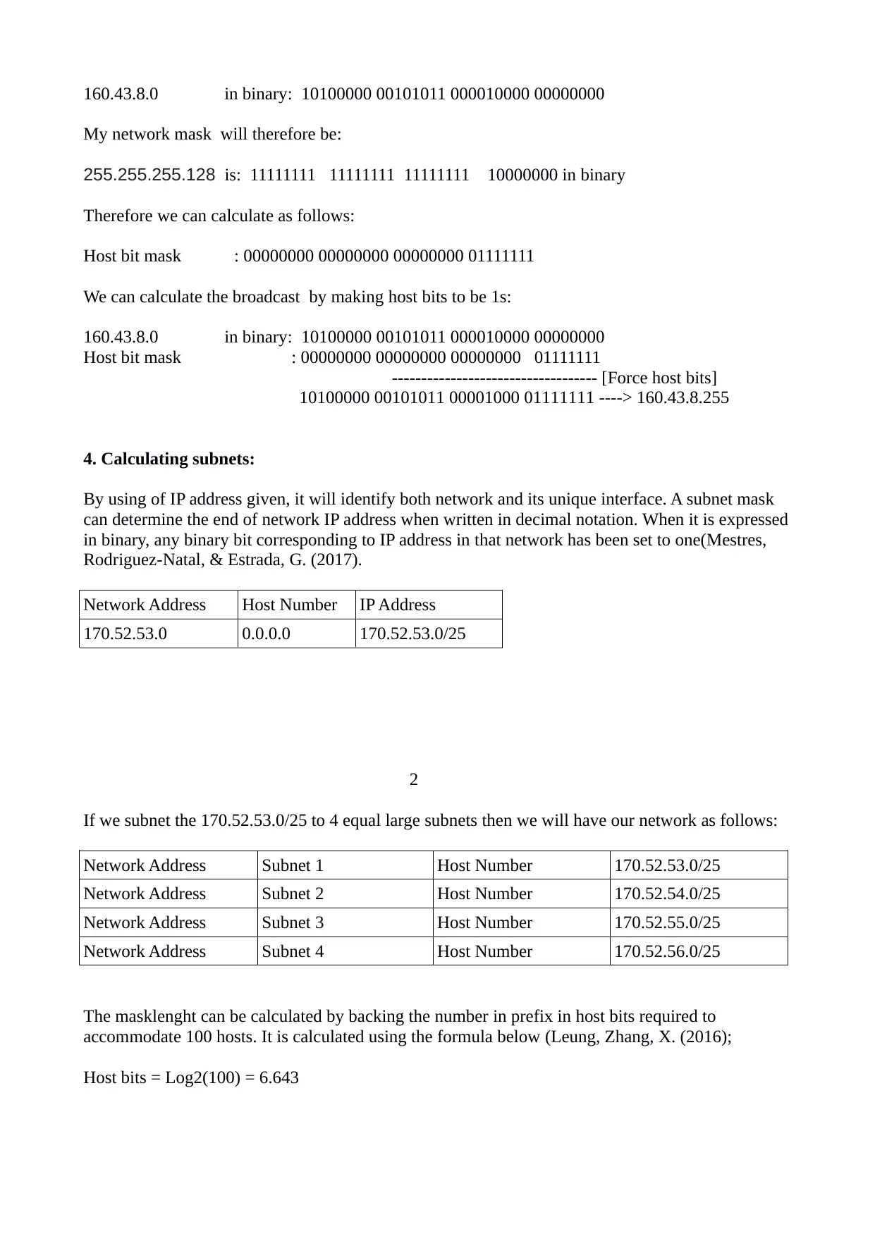
160.43.8.0 in binary: 10100000 00101011 000010000 00000000
My network mask will therefore be:
255.255.255.128 is: 11111111 11111111 11111111 10000000 in binary
Therefore we can calculate as follows:
Host bit mask : 00000000 00000000 00000000 01111111
We can calculate the broadcast by making host bits to be 1s:
160.43.8.0 in binary: 10100000 00101011 000010000 00000000
Host bit mask : 00000000 00000000 00000000 01111111
----------------------------------- [Force host bits]
10100000 00101011 00001000 01111111 ----> 160.43.8.255
4. Calculating subnets:
By using of IP address given, it will identify both network and its unique interface. A subnet mask
can determine the end of network IP address when written in decimal notation. When it is expressed
in binary, any binary bit corresponding to IP address in that network has been set to one(Mestres,
Rodriguez-Natal, & Estrada, G. (2017).
Network Address Host Number IP Address
170.52.53.0 0.0.0.0 170.52.53.0/25
2
If we subnet the 170.52.53.0/25 to 4 equal large subnets then we will have our network as follows:
Network Address Subnet 1 Host Number 170.52.53.0/25
Network Address Subnet 2 Host Number 170.52.54.0/25
Network Address Subnet 3 Host Number 170.52.55.0/25
Network Address Subnet 4 Host Number 170.52.56.0/25
The masklenght can be calculated by backing the number in prefix in host bits required to
accommodate 100 hosts. It is calculated using the formula below (Leung, Zhang, X. (2016);
Host bits = Log2(100) = 6.643
Subnet Network
Address
Mask First Host
Address
Last Host
Address
Broadcast Bit mask
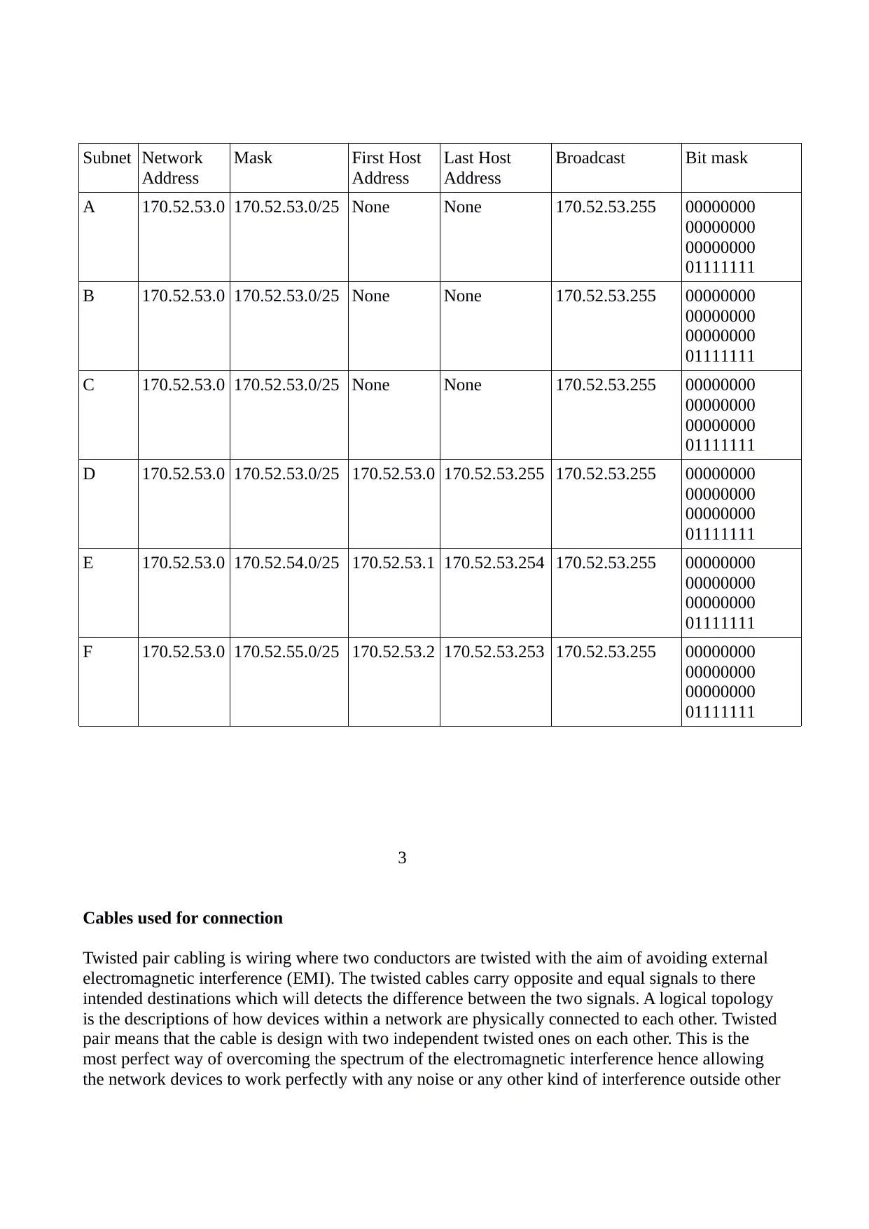
A 170.52.53.0 170.52.53.0/25 None None 170.52.53.255 00000000
00000000
00000000
01111111
B 170.52.53.0 170.52.53.0/25 None None 170.52.53.255 00000000
00000000
00000000
01111111
C 170.52.53.0 170.52.53.0/25 None None 170.52.53.255 00000000
00000000
00000000
01111111
D 170.52.53.0 170.52.53.0/25 170.52.53.0 170.52.53.255 170.52.53.255 00000000
00000000
00000000
01111111
E 170.52.53.0 170.52.54.0/25 170.52.53.1 170.52.53.254 170.52.53.255 00000000
00000000
00000000
01111111
F 170.52.53.0 170.52.55.0/25 170.52.53.2 170.52.53.253 170.52.53.255 00000000
00000000
00000000
01111111
3
Cables used for connection
Twisted pair cabling is wiring where two conductors are twisted with the aim of avoiding external
electromagnetic interference (EMI). The twisted cables carry opposite and equal signals to there
intended destinations which will detects the difference between the two signals. A logical topology
is the descriptions of how devices within a network are physically connected to each other. Twisted
pair means that the cable is design with two independent twisted ones on each other. This is the
most perfect way of overcoming the spectrum of the electromagnetic interference hence allowing
the network devices to work perfectly with any noise or any other kind of interference outside other
Address
Mask First Host
Address
Last Host
Address
Broadcast Bit mask
A 170.52.53.0 170.52.53.0/25 None None 170.52.53.255 00000000
00000000
00000000
01111111
B 170.52.53.0 170.52.53.0/25 None None 170.52.53.255 00000000
00000000
00000000
01111111
C 170.52.53.0 170.52.53.0/25 None None 170.52.53.255 00000000
00000000
00000000
01111111
D 170.52.53.0 170.52.53.0/25 170.52.53.0 170.52.53.255 170.52.53.255 00000000
00000000
00000000
01111111
E 170.52.53.0 170.52.54.0/25 170.52.53.1 170.52.53.254 170.52.53.255 00000000
00000000
00000000
01111111
F 170.52.53.0 170.52.55.0/25 170.52.53.2 170.52.53.253 170.52.53.255 00000000
00000000
00000000
01111111
3
Cables used for connection
Twisted pair cabling is wiring where two conductors are twisted with the aim of avoiding external
electromagnetic interference (EMI). The twisted cables carry opposite and equal signals to there
intended destinations which will detects the difference between the two signals. A logical topology
is the descriptions of how devices within a network are physically connected to each other. Twisted
pair means that the cable is design with two independent twisted ones on each other. This is the
most perfect way of overcoming the spectrum of the electromagnetic interference hence allowing
the network devices to work perfectly with any noise or any other kind of interference outside other
⊘ This is a preview!⊘
Do you want full access?
Subscribe today to unlock all pages.
Trusted by 1+ million students worldwide
sources. The logic is the network can be connected physically using wires and cables but also it can
be connect using wires devices as well. Sub-netting is process of utilizing larger networks by
dividing them into smaller sub-networks known as sub-nets. IP address is always used to to identify
the sub-net and for broadcasting also within the sub-net. Smaller networks create smaller broadcast
domains therefore less network broadcast traffic is experienced in the boundaries. Isolation of
network by trouble-shouting will simplify large networks when braked into smaller networks.
Switches and routers are the main components which facilitate the connection of the peripheral
devices in that particular network (van der Heijden, & Hartmann, 2016).
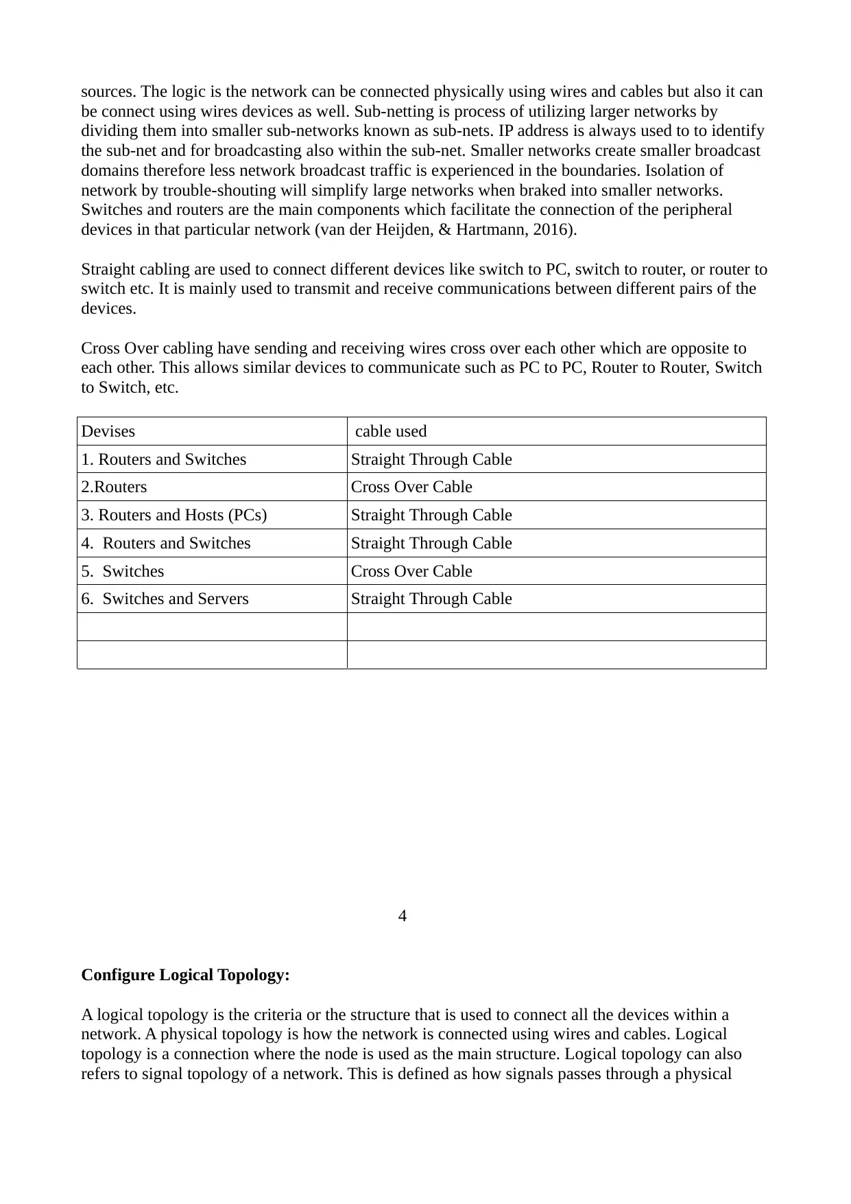
Straight cabling are used to connect different devices like switch to PC, switch to router, or router to
switch etc. It is mainly used to transmit and receive communications between different pairs of the
devices.
Cross Over cabling have sending and receiving wires cross over each other which are opposite to
each other. This allows similar devices to communicate such as PC to PC, Router to Router, Switch
to Switch, etc.
Devises cable used
1. Routers and Switches Straight Through Cable
2.Routers Cross Over Cable
3. Routers and Hosts (PCs) Straight Through Cable
4. Routers and Switches Straight Through Cable
5. Switches Cross Over Cable
6. Switches and Servers Straight Through Cable
4
Configure Logical Topology:
A logical topology is the criteria or the structure that is used to connect all the devices within a
network. A physical topology is how the network is connected using wires and cables. Logical
topology is a connection where the node is used as the main structure. Logical topology can also
refers to signal topology of a network. This is defined as how signals passes through a physical
be connect using wires devices as well. Sub-netting is process of utilizing larger networks by
dividing them into smaller sub-networks known as sub-nets. IP address is always used to to identify
the sub-net and for broadcasting also within the sub-net. Smaller networks create smaller broadcast
domains therefore less network broadcast traffic is experienced in the boundaries. Isolation of
network by trouble-shouting will simplify large networks when braked into smaller networks.
Switches and routers are the main components which facilitate the connection of the peripheral
devices in that particular network (van der Heijden, & Hartmann, 2016).
Straight cabling are used to connect different devices like switch to PC, switch to router, or router to
switch etc. It is mainly used to transmit and receive communications between different pairs of the
devices.
Cross Over cabling have sending and receiving wires cross over each other which are opposite to
each other. This allows similar devices to communicate such as PC to PC, Router to Router, Switch
to Switch, etc.
Devises cable used
1. Routers and Switches Straight Through Cable
2.Routers Cross Over Cable
3. Routers and Hosts (PCs) Straight Through Cable
4. Routers and Switches Straight Through Cable
5. Switches Cross Over Cable
6. Switches and Servers Straight Through Cable
4
Configure Logical Topology:
A logical topology is the criteria or the structure that is used to connect all the devices within a
network. A physical topology is how the network is connected using wires and cables. Logical
topology is a connection where the node is used as the main structure. Logical topology can also
refers to signal topology of a network. This is defined as how signals passes through a physical
Paraphrase This Document
Need a fresh take? Get an instant paraphrase of this document with our AI Paraphraser
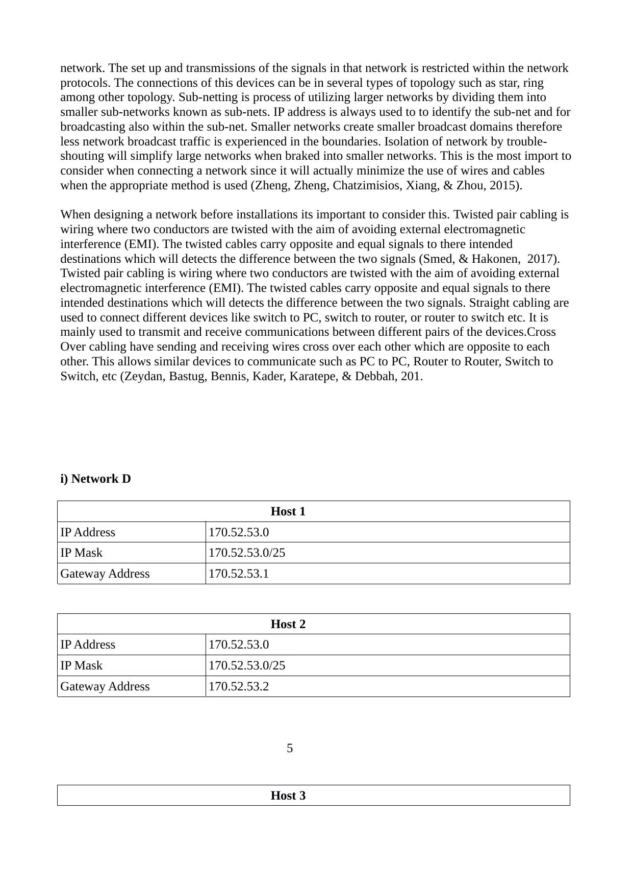
network. The set up and transmissions of the signals in that network is restricted within the network
protocols. The connections of this devices can be in several types of topology such as star, ring
among other topology. Sub-netting is process of utilizing larger networks by dividing them into
smaller sub-networks known as sub-nets. IP address is always used to to identify the sub-net and for
broadcasting also within the sub-net. Smaller networks create smaller broadcast domains therefore
less network broadcast traffic is experienced in the boundaries. Isolation of network by trouble-
shouting will simplify large networks when braked into smaller networks. This is the most import to
consider when connecting a network since it will actually minimize the use of wires and cables
when the appropriate method is used (Zheng, Zheng, Chatzimisios, Xiang, & Zhou, 2015).
When designing a network before installations its important to consider this. Twisted pair cabling is
wiring where two conductors are twisted with the aim of avoiding external electromagnetic
interference (EMI). The twisted cables carry opposite and equal signals to there intended
destinations which will detects the difference between the two signals (Smed, & Hakonen, 2017).
Twisted pair cabling is wiring where two conductors are twisted with the aim of avoiding external
electromagnetic interference (EMI). The twisted cables carry opposite and equal signals to there
intended destinations which will detects the difference between the two signals. Straight cabling are
used to connect different devices like switch to PC, switch to router, or router to switch etc. It is
mainly used to transmit and receive communications between different pairs of the devices.Cross
Over cabling have sending and receiving wires cross over each other which are opposite to each
other. This allows similar devices to communicate such as PC to PC, Router to Router, Switch to
Switch, etc (Zeydan, Bastug, Bennis, Kader, Karatepe, & Debbah, 201.
i) Network D
Host 1
IP Address 170.52.53.0
IP Mask 170.52.53.0/25
Gateway Address 170.52.53.1
Host 2
IP Address 170.52.53.0
IP Mask 170.52.53.0/25
Gateway Address 170.52.53.2
5
Host 3
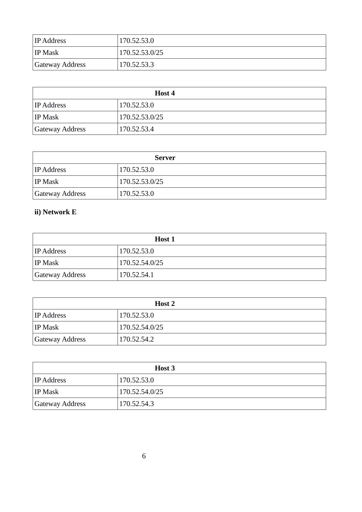
IP Address 170.52.53.0
IP Mask 170.52.53.0/25
Gateway Address 170.52.53.3
Host 4
IP Address 170.52.53.0
IP Mask 170.52.53.0/25
Gateway Address 170.52.53.4
Server
IP Address 170.52.53.0
IP Mask 170.52.53.0/25
Gateway Address 170.52.53.0
ii) Network E
Host 1
IP Address 170.52.53.0
IP Mask 170.52.54.0/25
Gateway Address 170.52.54.1
Host 2
IP Address 170.52.53.0
IP Mask 170.52.54.0/25
Gateway Address 170.52.54.2
Host 3
IP Address 170.52.53.0
IP Mask 170.52.54.0/25
Gateway Address 170.52.54.3
6
IP Mask 170.52.53.0/25
Gateway Address 170.52.53.3
Host 4
IP Address 170.52.53.0
IP Mask 170.52.53.0/25
Gateway Address 170.52.53.4
Server
IP Address 170.52.53.0
IP Mask 170.52.53.0/25
Gateway Address 170.52.53.0
ii) Network E
Host 1
IP Address 170.52.53.0
IP Mask 170.52.54.0/25
Gateway Address 170.52.54.1
Host 2
IP Address 170.52.53.0
IP Mask 170.52.54.0/25
Gateway Address 170.52.54.2
Host 3
IP Address 170.52.53.0
IP Mask 170.52.54.0/25
Gateway Address 170.52.54.3
6
⊘ This is a preview!⊘
Do you want full access?
Subscribe today to unlock all pages.
Trusted by 1+ million students worldwide
1 out of 55
Related Documents


Your All-in-One AI-Powered Toolkit for Academic Success.
+13062052269
info@desklib.com
Available 24*7 on WhatsApp / Email
![[object Object]](/_next/static/media/star-bottom.7253800d.svg)
Unlock your academic potential
Copyright © 2020–2026 A2Z Services. All Rights Reserved. Developed and managed by ZUCOL.