Network Design Assessment 4 Report: Network Configuration & Design
VerifiedAdded on 2021/06/16
|26
|2054
|20
Report
AI Summary
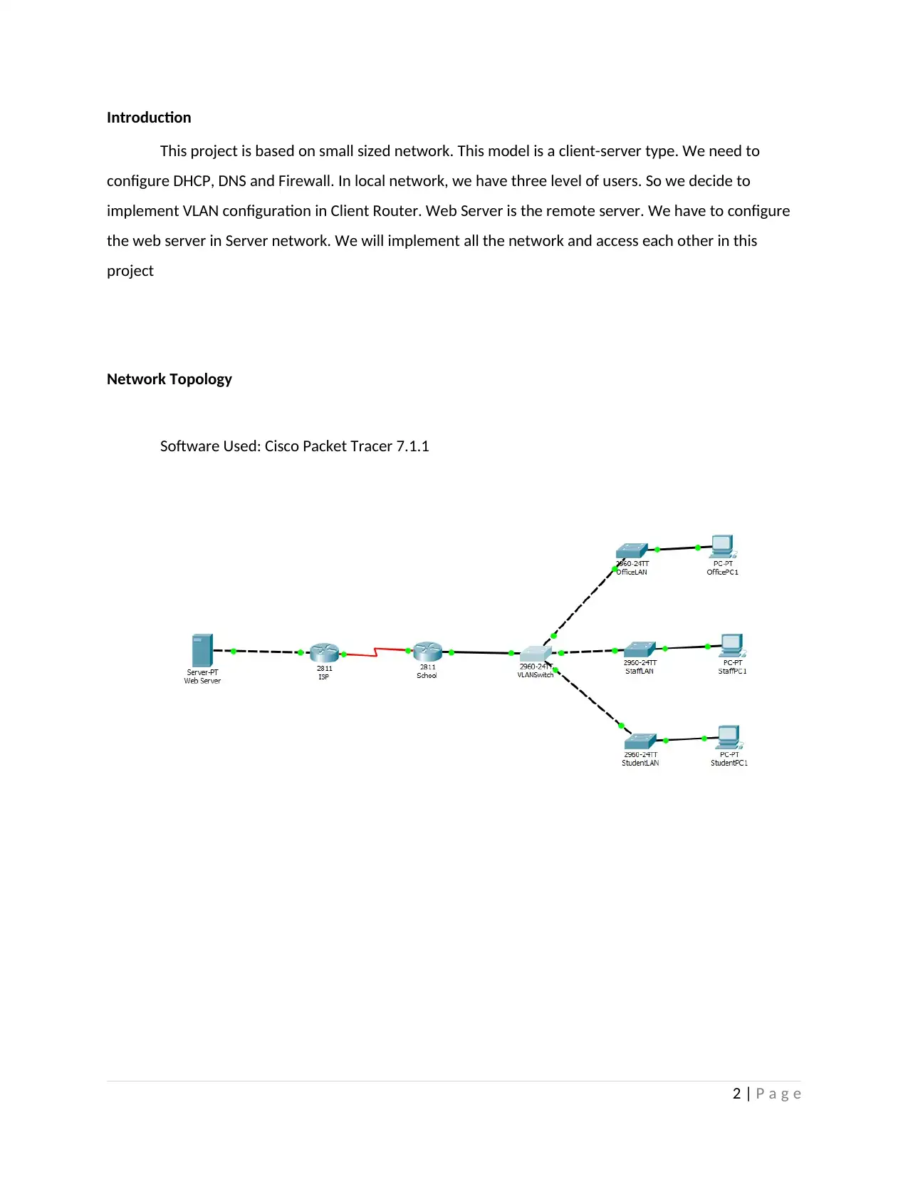
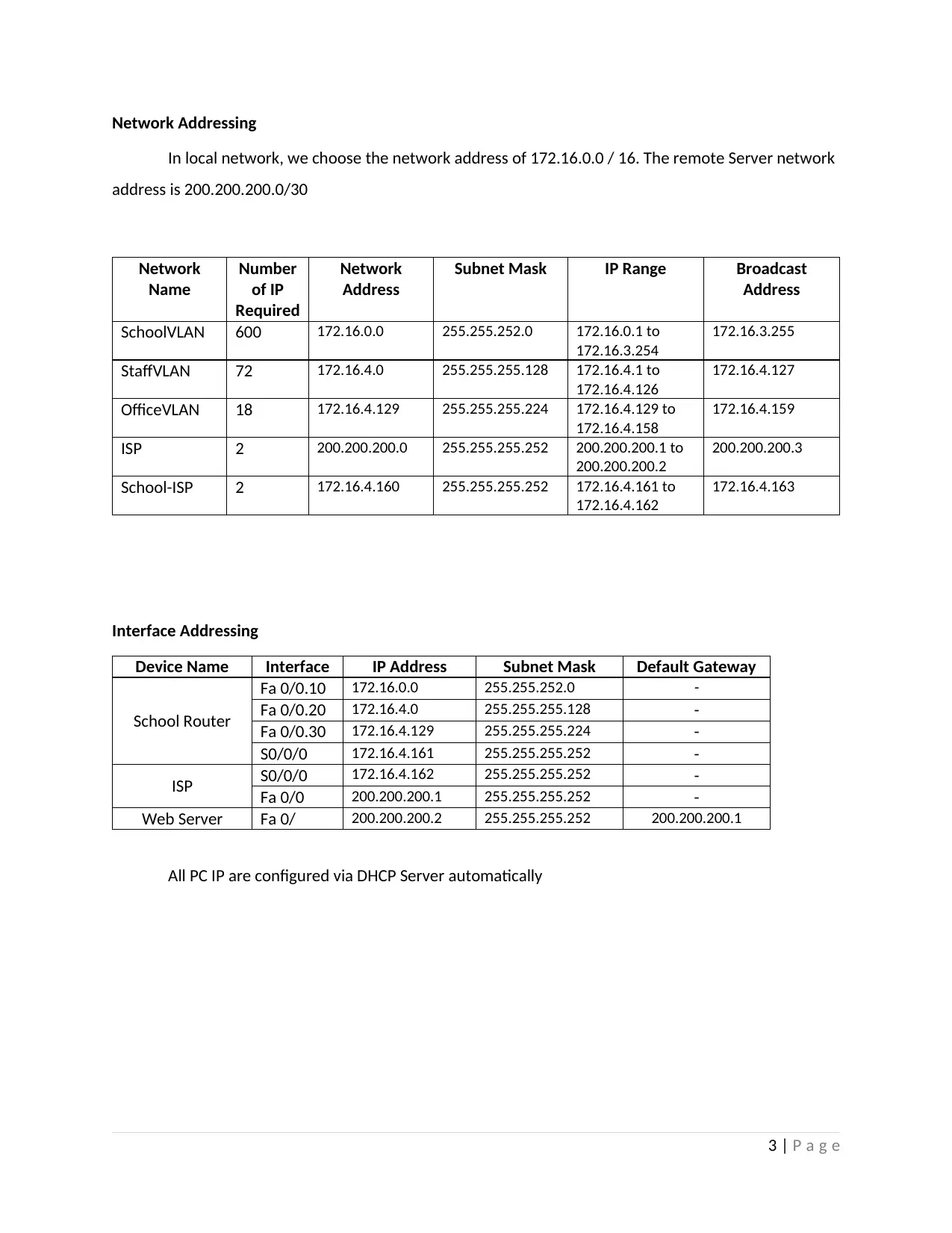
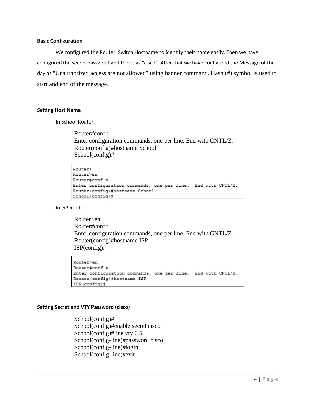
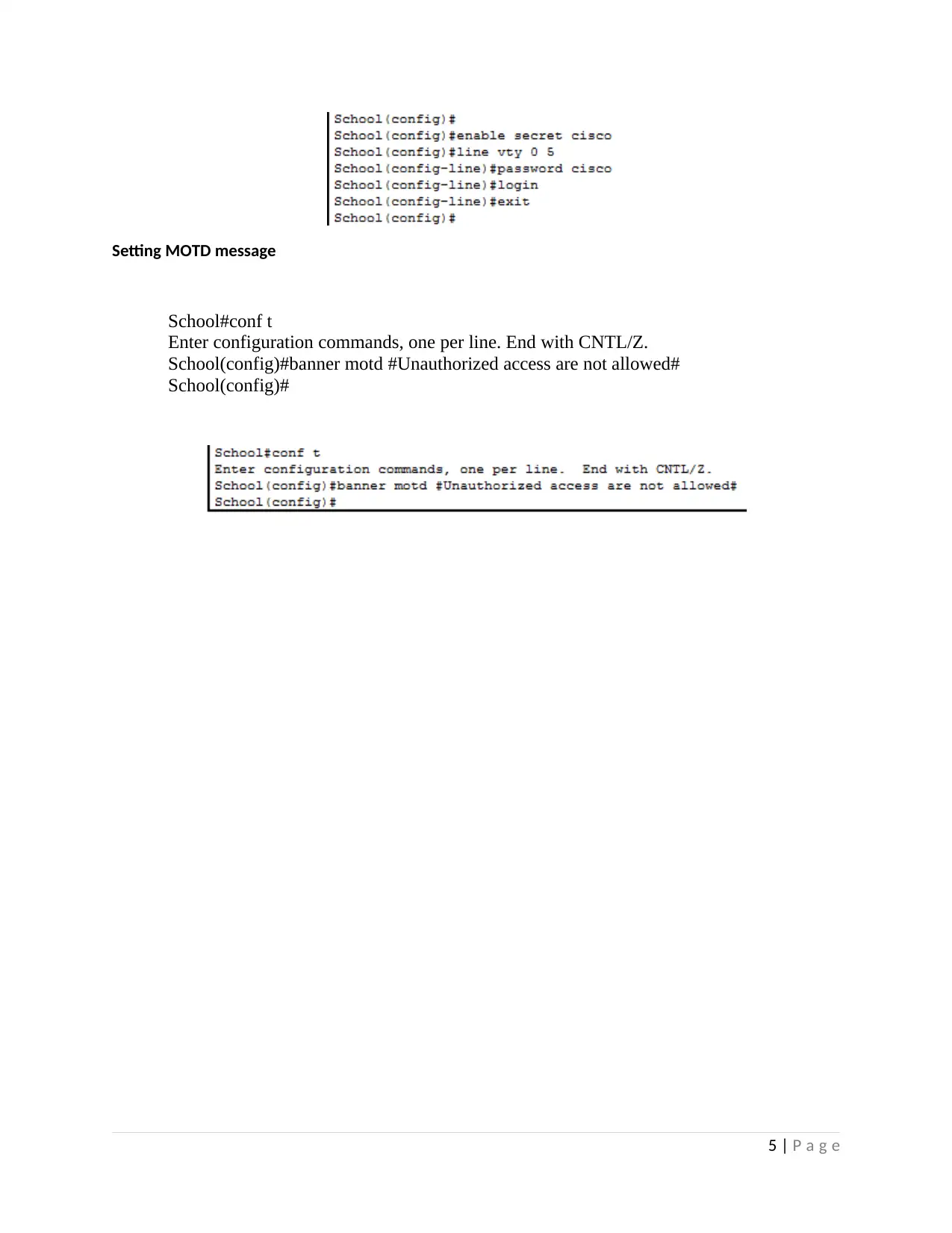
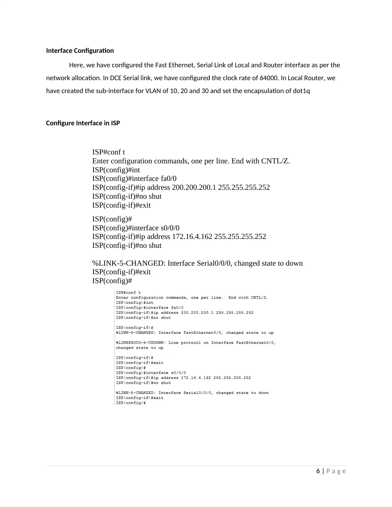
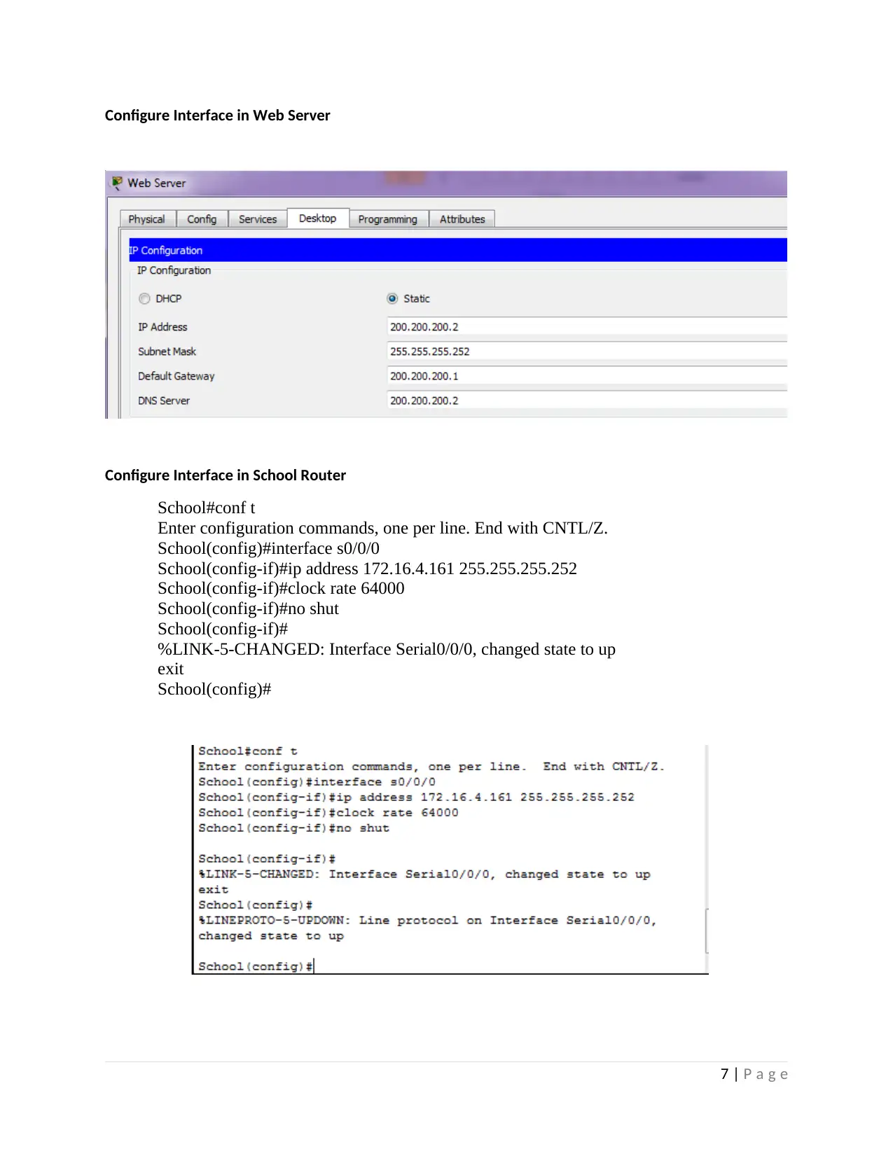
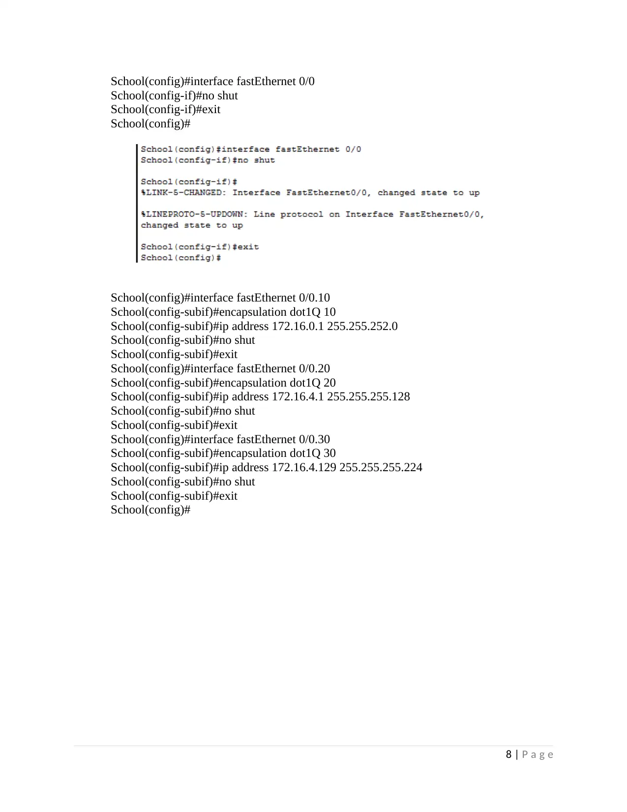
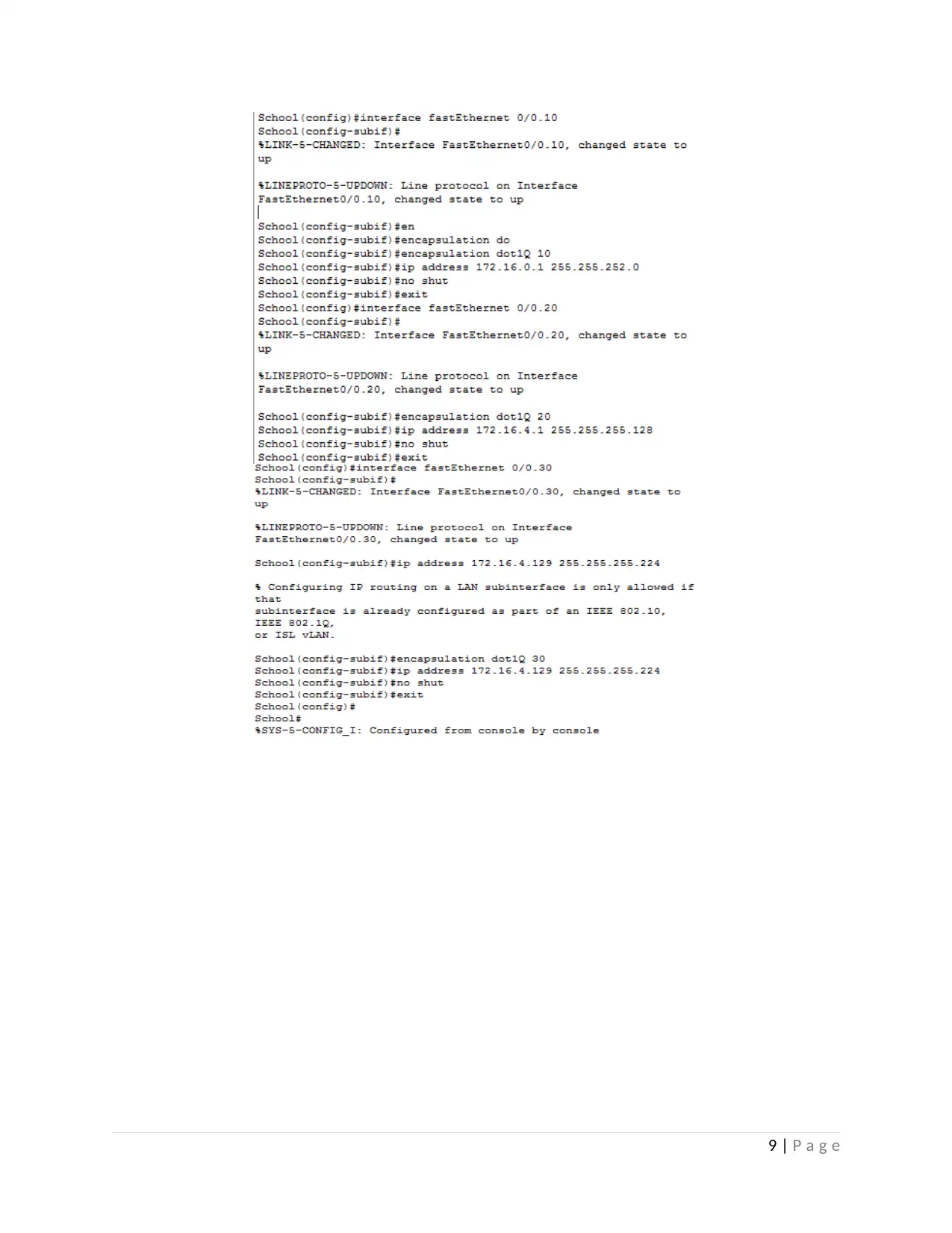
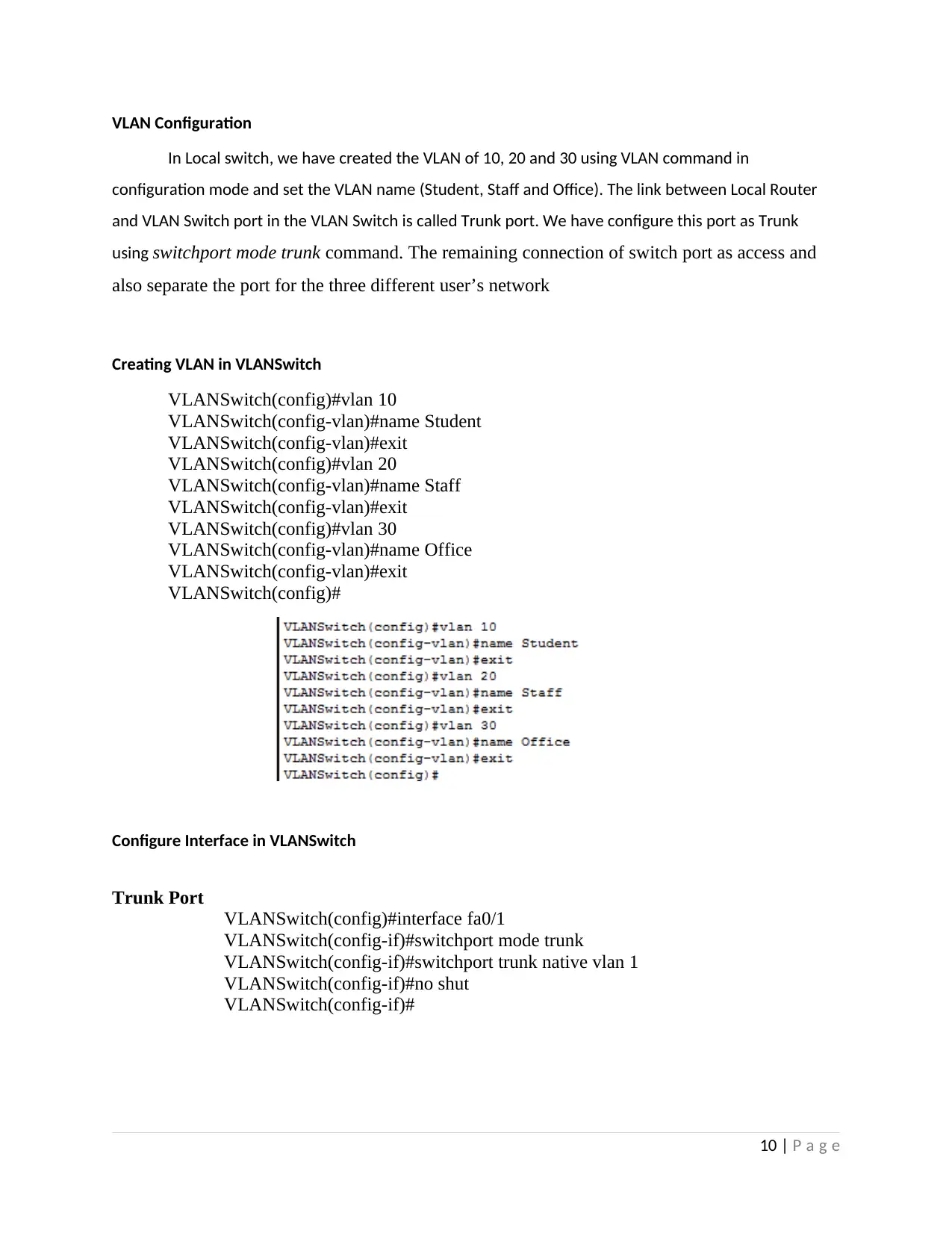
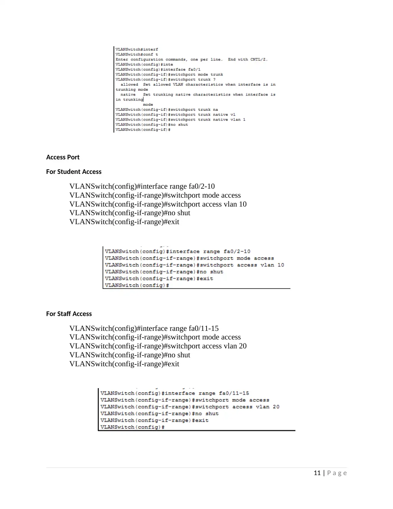
This report details a network design project implemented using Cisco Packet Tracer. The project focuses on a client-server network model, incorporating VLAN configuration for different user groups (School, Staff, Office), DHCP server setup for automatic IP address allocation, DNS server configuration for web server access, and firewall implementation to control network access. The report covers network addressing, interface configuration, basic device configurations (hostname, passwords, MOTD), VLAN creation and trunk port configuration, DHCP pool creation, RIP routing configuration, and web server setup. It also includes firewall configuration using access control lists (ACLs) to restrict web server access, followed by comprehensive testing of network connectivity and functionality, including ping tests and web server access tests. The document concludes with a summary of the project and its outcomes, along with references to relevant documentation.

5/11/2018
Network Design
Assessment 4
BHARGAV CHAND
Student ID
Network Design
Assessment 4
BHARGAV CHAND
Student ID
Paraphrase This Document
Need a fresh take? Get an instant paraphrase of this document with our AI Paraphraser

Table of Contents
Sl. No Content Page No
1 Introduction 2
2 Network and Interface Addressing 3
3 Basic Configuration 4
4 Interface Configuration 6
5 VLAN Configuration 10
6 DHCP Server Configuration 12
7 Web Server and DNS Configuration 15
8 Firewall Configuration 17
9 Testing 20
10 Conclusion 24
References 25
1 | P a g e

Introduction
This project is based on small sized network. This model is a client-server type. We need to
configure DHCP, DNS and Firewall. In local network, we have three level of users. So we decide to
implement VLAN configuration in Client Router. Web Server is the remote server. We have to configure
the web server in Server network. We will implement all the network and access each other in this
project
Network Topology
Software Used: Cisco Packet Tracer 7.1.1
2 | P a g e
⊘ This is a preview!⊘
Do you want full access?
Subscribe today to unlock all pages.

Trusted by 1+ million students worldwide

Network Addressing
In local network, we choose the network address of 172.16.0.0 / 16. The remote Server network
address is 200.200.200.0/30
Network
Name
Number
of IP
Required
Network
Address
Subnet Mask IP Range Broadcast
Address
SchoolVLAN 600 172.16.0.0 255.255.252.0 172.16.0.1 to
172.16.3.254
172.16.3.255
StaffVLAN 72 172.16.4.0 255.255.255.128 172.16.4.1 to
172.16.4.126
172.16.4.127
OfficeVLAN 18 172.16.4.129 255.255.255.224 172.16.4.129 to
172.16.4.158
172.16.4.159
ISP 2 200.200.200.0 255.255.255.252 200.200.200.1 to
200.200.200.2
200.200.200.3
School-ISP 2 172.16.4.160 255.255.255.252 172.16.4.161 to
172.16.4.162
172.16.4.163
Interface Addressing
Device Name Interface IP Address Subnet Mask Default Gateway
School Router
Fa 0/0.10 172.16.0.0 255.255.252.0 -
Fa 0/0.20 172.16.4.0 255.255.255.128 -
Fa 0/0.30 172.16.4.129 255.255.255.224 -
S0/0/0 172.16.4.161 255.255.255.252 -
ISP S0/0/0 172.16.4.162 255.255.255.252 -
Fa 0/0 200.200.200.1 255.255.255.252 -
Web Server Fa 0/ 200.200.200.2 255.255.255.252 200.200.200.1
All PC IP are configured via DHCP Server automatically
3 | P a g e
Paraphrase This Document
Need a fresh take? Get an instant paraphrase of this document with our AI Paraphraser

Basic Configuration
We configured the Router, Switch Hostname to identify their name easily. Then we have
configured the secret password and telnet as “cisco”. After that we have configured the Message of the
day as “Unauthorized access are not allowed” using banner command. Hash (#) symbol is used to
start and end of the message.
Setting Host Name
In School Router,
Router#conf t
Enter configuration commands, one per line. End with CNTL/Z.
Router(config)#hostname School
School(config)#
In ISP Router,
Router>en
Router#conf t
Enter configuration commands, one per line. End with CNTL/Z.
Router(config)#hostname ISP
ISP(config)#
Setting Secret and VTY Password (cisco)
School(config)#
School(config)#enable secret cisco
School(config)#line vty 0 5
School(config-line)#password cisco
School(config-line)#login
School(config-line)#exit
4 | P a g e

Setting MOTD message
School#conf t
Enter configuration commands, one per line. End with CNTL/Z.
School(config)#banner motd #Unauthorized access are not allowed#
School(config)#
5 | P a g e
School#conf t
Enter configuration commands, one per line. End with CNTL/Z.
School(config)#banner motd #Unauthorized access are not allowed#
School(config)#
5 | P a g e
⊘ This is a preview!⊘
Do you want full access?
Subscribe today to unlock all pages.

Trusted by 1+ million students worldwide

Interface Configuration
Here, we have configured the Fast Ethernet, Serial Link of Local and Router interface as per the
network allocation. In DCE Serial link, we have configured the clock rate of 64000. In Local Router, we
have created the sub-interface for VLAN of 10, 20 and 30 and set the encapsulation of dot1q
Configure Interface in ISP
ISP#conf t
Enter configuration commands, one per line. End with CNTL/Z.
ISP(config)#int
ISP(config)#interface fa0/0
ISP(config-if)#ip address 200.200.200.1 255.255.255.252
ISP(config-if)#no shut
ISP(config-if)#exit
ISP(config)#
ISP(config)#interface s0/0/0
ISP(config-if)#ip address 172.16.4.162 255.255.255.252
ISP(config-if)#no shut
%LINK-5-CHANGED: Interface Serial0/0/0, changed state to down
ISP(config-if)#exit
ISP(config)#
6 | P a g e
Paraphrase This Document
Need a fresh take? Get an instant paraphrase of this document with our AI Paraphraser

Configure Interface in Web Server
Configure Interface in School Router
School#conf t
Enter configuration commands, one per line. End with CNTL/Z.
School(config)#interface s0/0/0
School(config-if)#ip address 172.16.4.161 255.255.255.252
School(config-if)#clock rate 64000
School(config-if)#no shut
School(config-if)#
%LINK-5-CHANGED: Interface Serial0/0/0, changed state to up
exit
School(config)#
7 | P a g e

School(config)#interface fastEthernet 0/0
School(config-if)#no shut
School(config-if)#exit
School(config)#
School(config)#interface fastEthernet 0/0.10
School(config-subif)#encapsulation dot1Q 10
School(config-subif)#ip address 172.16.0.1 255.255.252.0
School(config-subif)#no shut
School(config-subif)#exit
School(config)#interface fastEthernet 0/0.20
School(config-subif)#encapsulation dot1Q 20
School(config-subif)#ip address 172.16.4.1 255.255.255.128
School(config-subif)#no shut
School(config-subif)#exit
School(config)#interface fastEthernet 0/0.30
School(config-subif)#encapsulation dot1Q 30
School(config-subif)#ip address 172.16.4.129 255.255.255.224
School(config-subif)#no shut
School(config-subif)#exit
School(config)#
8 | P a g e
⊘ This is a preview!⊘
Do you want full access?
Subscribe today to unlock all pages.

Trusted by 1+ million students worldwide

9 | P a g e
Paraphrase This Document
Need a fresh take? Get an instant paraphrase of this document with our AI Paraphraser

VLAN Configuration
In Local switch, we have created the VLAN of 10, 20 and 30 using VLAN command in
configuration mode and set the VLAN name (Student, Staff and Office). The link between Local Router
and VLAN Switch port in the VLAN Switch is called Trunk port. We have configure this port as Trunk
using switchport mode trunk command. The remaining connection of switch port as access and
also separate the port for the three different user’s network
Creating VLAN in VLANSwitch
VLANSwitch(config)#vlan 10
VLANSwitch(config-vlan)#name Student
VLANSwitch(config-vlan)#exit
VLANSwitch(config)#vlan 20
VLANSwitch(config-vlan)#name Staff
VLANSwitch(config-vlan)#exit
VLANSwitch(config)#vlan 30
VLANSwitch(config-vlan)#name Office
VLANSwitch(config-vlan)#exit
VLANSwitch(config)#
Configure Interface in VLANSwitch
Trunk Port
VLANSwitch(config)#interface fa0/1
VLANSwitch(config-if)#switchport mode trunk
VLANSwitch(config-if)#switchport trunk native vlan 1
VLANSwitch(config-if)#no shut
VLANSwitch(config-if)#
10 | P a g e

Access Port
For Student Access
VLANSwitch(config)#interface range fa0/2-10
VLANSwitch(config-if-range)#switchport mode access
VLANSwitch(config-if-range)#switchport access vlan 10
VLANSwitch(config-if-range)#no shut
VLANSwitch(config-if-range)#exit
For Staff Access
VLANSwitch(config)#interface range fa0/11-15
VLANSwitch(config-if-range)#switchport mode access
VLANSwitch(config-if-range)#switchport access vlan 20
VLANSwitch(config-if-range)#no shut
VLANSwitch(config-if-range)#exit
11 | P a g e
⊘ This is a preview!⊘
Do you want full access?
Subscribe today to unlock all pages.

Trusted by 1+ million students worldwide
1 out of 26
Related Documents
Your All-in-One AI-Powered Toolkit for Academic Success.
+13062052269
info@desklib.com
Available 24*7 on WhatsApp / Email
Unlock your academic potential
Copyright © 2020–2025 A2Z Services. All Rights Reserved. Developed and managed by ZUCOL.


