Network Design with Multiple VLANs for Automotive Supplier Company HQ
VerifiedAdded on  2023/06/12
|46
|1310
|486
Project
AI Summary
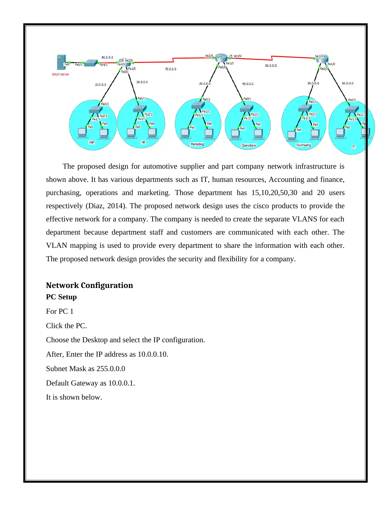
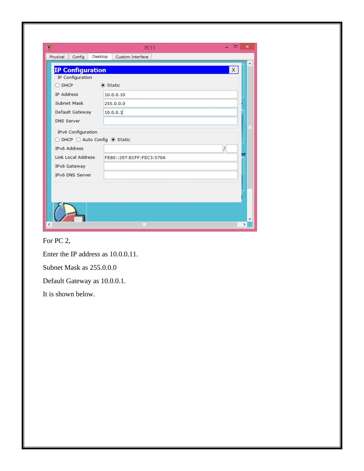
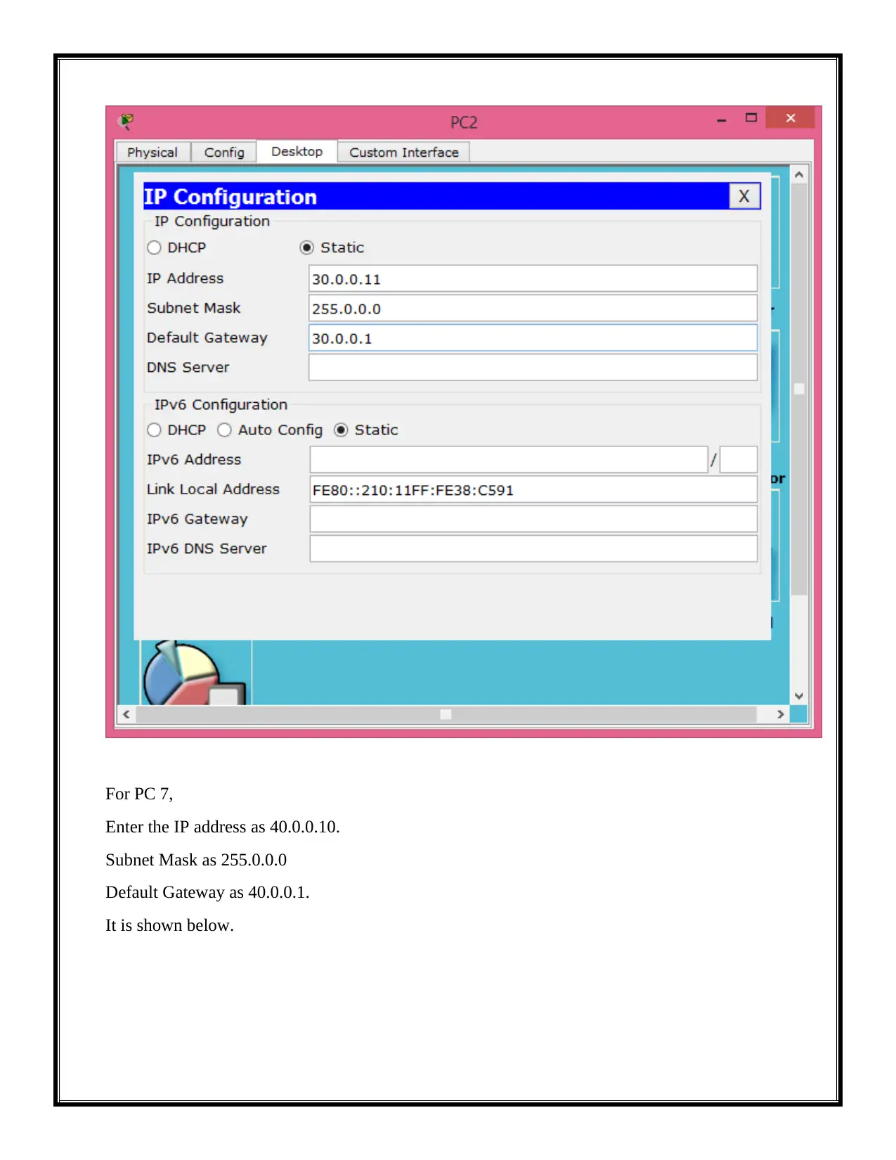
This project outlines the design and configuration of a network with multiple VLANs for a major automotive supplier relocating to Tennessee. The design caters to various departments including IT, Human Resources, Accounting & Finance, Purchasing, Operations, and Marketing, each with specific user counts and VLAN requirements. The project details hardware and software components, including Cisco routers and switches, and provides step-by-step configurations for PCs, switches, and routers using Cisco Packet Tracer. It covers VLAN and IP mapping, DHCP server configuration, and network testing procedures. Additionally, the project addresses network security concerns, incorporating measures to protect stored and transmitted data. This document, contributed by a student, is available on Desklib, offering a valuable resource for understanding VLAN network design and implementation.

Design a Network with Multiple VLANS
Paraphrase This Document
Need a fresh take? Get an instant paraphrase of this document with our AI Paraphraser

Contents
Project Scope...............................................................................................................................................3
Project Requirements...................................................................................................................................3
Hardware and Software...............................................................................................................................3
Network Configuration................................................................................................................................4
Switch configuration................................................................................................................................16
Router Configuration...............................................................................................................................22
DHCP server Configuration.....................................................................................................................28
DHCP configuration on router................................................................................................................31
IP and VLAN Mapping..............................................................................................................................31
Network Testing......................................................................................................................................41
References................................................................................................................................................44

⊘ This is a preview!⊘
Do you want full access?
Subscribe today to unlock all pages.

Trusted by 1+ million students worldwide

Project Scope
The main scope of this project is to design a network with Multiple VLANS. It is major
automotive supplier and parts company that is relocated to Tennessee. This company has decided
to create a new network design and to configure as per the project requirement. It has various
departments such as IT, human resources, Accounting and finance, purchasing, operation and
marketing. Those department has 15,10,20,50,30 and 20 users respectively. The network design
is needed to create the separate VLAN for each department. The company obtains the access to
internet through internet service provider. The network design will be created by using cisoc
packet tracer. It is very useful tool to create the effective network. The new design provides the
effective and efficient network for a company.
Project Requirements
The project requirement is to create the new network with multiple VLANs because the
company has the various departments. Each department is needed to create the separate VLAN.
The new network will be designed and the design configurations are done (A, 2014). The VLAN
using the top down methodology to provide the effective network for a company. The top down
methodology is one of the network strategy.
Hardware and Software
The Network Design hardware and software information is shown below.
Hardware component
1. Cisco Routers
2. Cisco Switches
3. Cisco server
Software Component
Personal computer with 2 GB RAM, 2.25 Memory and Inter core processor.
Network Topology Diagram
The network design is shown below.
Paraphrase This Document
Need a fresh take? Get an instant paraphrase of this document with our AI Paraphraser

The proposed design for automotive supplier and part company network infrastructure is
shown above. It has various departments such as IT, human resources, Accounting and finance,
purchasing, operations and marketing. Those department has 15,10,20,50,30 and 20 users
respectively (Diaz, 2014). The proposed network design uses the cisco products to provide the
effective network for a company. The company is needed to create the separate VLANS for each
department because department staff and customers are communicated with each other. The
VLAN mapping is used to provide every department to share the information with each other.
The proposed network design provides the security and flexibility for a company.
Network Configuration
PC Setup
For PC 1
Click the PC.
Choose the Desktop and select the IP configuration.
After, Enter the IP address as 10.0.0.10.
Subnet Mask as 255.0.0.0
Default Gateway as 10.0.0.1.
It is shown below.

For PC 2,
Enter the IP address as 10.0.0.11.
Subnet Mask as 255.0.0.0
Default Gateway as 10.0.0.1.
It is shown below.
Enter the IP address as 10.0.0.11.
Subnet Mask as 255.0.0.0
Default Gateway as 10.0.0.1.
It is shown below.
⊘ This is a preview!⊘
Do you want full access?
Subscribe today to unlock all pages.

Trusted by 1+ million students worldwide

For PC 3,
Enter the IP address as 20.0.0.10.
Subnet Mask as 255.0.0.0
Default Gateway as 20.0.0.1.
It is shown below.
Enter the IP address as 20.0.0.10.
Subnet Mask as 255.0.0.0
Default Gateway as 20.0.0.1.
It is shown below.
Paraphrase This Document
Need a fresh take? Get an instant paraphrase of this document with our AI Paraphraser

For PC 4,
Enter the IP address as 20.0.0.11.
Subnet Mask as 255.0.0.0
Default Gateway as 20.0.0.1.
It is shown below.
Enter the IP address as 20.0.0.11.
Subnet Mask as 255.0.0.0
Default Gateway as 20.0.0.1.
It is shown below.

For PC 5,
Enter the IP address as 30.0.0.10.
Subnet Mask as 255.0.0.0
Default Gateway as 30.0.0.1.
It is shown below.
Enter the IP address as 30.0.0.10.
Subnet Mask as 255.0.0.0
Default Gateway as 30.0.0.1.
It is shown below.
⊘ This is a preview!⊘
Do you want full access?
Subscribe today to unlock all pages.

Trusted by 1+ million students worldwide

For PC 6,
Enter the IP address as 30.0.0.11.
Subnet Mask as 255.0.0.0
Default Gateway as 30.0.0.1.
It is shown below.
Enter the IP address as 30.0.0.11.
Subnet Mask as 255.0.0.0
Default Gateway as 30.0.0.1.
It is shown below.
Paraphrase This Document
Need a fresh take? Get an instant paraphrase of this document with our AI Paraphraser

For PC 7,
Enter the IP address as 40.0.0.10.
Subnet Mask as 255.0.0.0
Default Gateway as 40.0.0.1.
It is shown below.
Enter the IP address as 40.0.0.10.
Subnet Mask as 255.0.0.0
Default Gateway as 40.0.0.1.
It is shown below.

For PC 8,
Enter the IP address as 40.0.0.11.
Subnet Mask as 255.0.0.0
Default Gateway as 40.0.0.1.
It is shown below.
Enter the IP address as 40.0.0.11.
Subnet Mask as 255.0.0.0
Default Gateway as 40.0.0.1.
It is shown below.
⊘ This is a preview!⊘
Do you want full access?
Subscribe today to unlock all pages.

Trusted by 1+ million students worldwide
1 out of 46
Related Documents

Your All-in-One AI-Powered Toolkit for Academic Success.
 +13062052269
info@desklib.com
Available 24*7 on WhatsApp / Email
Unlock your academic potential
Copyright © 2020–2025 A2Z Services. All Rights Reserved. Developed and managed by ZUCOL.