Network Design Case Study of LUCMAT LTD: Implementation and Testing
VerifiedAdded on 2022/11/25
|32
|6131
|456
Report
AI Summary
This report presents a comprehensive network design case study for LUCMAT LTD, addressing the company's need for an upgraded network infrastructure to accommodate its growing workforce across three departments: HR, Design, and Sales. The study begins with an overview of networking principles and protocols, including a detailed examination of various network topologies such as bus, ring, mesh, star, and tree, with a specific focus on the advantages and disadvantages of each. The report then delves into the selection of a star topology for LUCMAT LTD, justifying this choice based on scalability and ease of management. The discussion extends to the impact of network topology on communication and bandwidth. Furthermore, it covers networking devices like hubs, routers, switches, and servers, and the design of efficient networked systems. The report also details the implementation process, including network testing and evaluation using ping tests, and concludes with a maintenance schedule and recommendations for optimal network performance.

Network Design
Case Study of LUCMAT LTD
Student Name
Institution Affiliation
Case Study of LUCMAT LTD
Student Name
Institution Affiliation
Paraphrase This Document
Need a fresh take? Get an instant paraphrase of this document with our AI Paraphraser
Table of Contents
Table of Contents........................................................................................................................................2
List of Figures.............................................................................................................................................3
List of Tables...............................................................................................................................................3
Introduction.................................................................................................................................................4
Networking Principles & Protocols.............................................................................................................5
Topology.................................................................................................................................................5
Bus topology........................................................................................................................................6
Ring Topology.....................................................................................................................................6
Mesh Topology....................................................................................................................................7
Star Topology......................................................................................................................................7
Tree Topology.....................................................................................................................................8
Impact of Network Topology Communication and Bandwidth...............................................................8
Protocols................................................................................................................................................10
Internet Protocol................................................................................................................................10
Transmission Control Protocol (TCP)...............................................................................................10
Wireless Network Protocols..............................................................................................................10
OSI Model.........................................................................................................................................10
Selected Physical Network Topology....................................................................................................11
Networking Devices and Operations.........................................................................................................11
Hub........................................................................................................................................................11
Router....................................................................................................................................................12
Switch....................................................................................................................................................12
Network Interface Card.........................................................................................................................12
Gateway.................................................................................................................................................12
Server....................................................................................................................................................13
Design Efficient Networked Systems........................................................................................................16
Testing and Evaluation..........................................................................................................................18
Ping Test............................................................................................................................................22
Maintenance Schedule...........................................................................................................................23
Implement and diagnose networked systems.............................................................................................25
Implementation of the Network System................................................................................................25
Document and testing of the Second network Design............................................................................27
Recommendations.................................................................................................................................29
Critical Reflection.................................................................................................................................30
Conclusions...............................................................................................................................................30
List References..........................................................................................................................................32
List of Figures
Figure 1 LUCMAT NETWORK DESIGN...................................................................................16
Figure 2 Test for printer 2 HR in HR Department.........................................................................19
Figure 3 Test for PC5 Sales in Sales Department..........................................................................20
Figure 4 Test for Printer 5 Design in Design Department.............................................................20
Figure 5 File Server.......................................................................................................................21
Figure 6 Testing if the Devices communicate via messages.........................................................22
Figure 7 Pinging for PC0 in PC5 in sales department...................................................................23
Figure 8Pinging for File Server in PC11 in Design department....................................................24
List of Tables
Table 1 Maintenance Schedule Plan..............................................................................................25
Table 2 Improved Network Design with Wireless connections and Firewalls.............................27
Table 3 Wireless PC can see the LUCMAT LTD WIRELESS connections................................28
Table 4 Wireless messaging to other devices................................................................................29
Table 5 Pinging IP 192.168.10.5 and 192.168.10.9 on Wireless PC.............................................29
Table 6 Laptop and Tablet test that they communicate with all other devices..............................30
⊘ This is a preview!⊘
Do you want full access?
Subscribe today to unlock all pages.
Trusted by 1+ million students worldwide
Introduction.
Networking is a very broad area in any discussion. In any case, with regards to
networking is good for one to know if one is installing it from scratch or one is upgrading the
existing network. In this case of LUCMAT Ltd, the objective is to design and implement its
network infrastructure as an upgrade due to its requirements such as the increment of employees
and thus existing network need an upgrade to accommodate the additional members. The idea is
to extend the existing network. The company has about three departments namely HR, Design
and the Sales Departments respectively. The computers and printers have been shared as follows:
HR: 8 Printers and printers
Design: 35 Printers and Printers
Sales: 40 PCs and printers.
There are also three servers installed in the network to accommodate storage, domain and
email sending and receiving namely the web, DNS and Email server respectively. The company
has been using the private IP address 192.168.10.0/24 all through. In this case, there is need to do
the design and implement the system according to the new requirements given by the company
network administrator. The work will also ensure that the network has been assessed for any
malfunctions may it being in the routers or the switches to avoid future problems after the
expansion. The system design expected will help one in doing maintenance schedules, network
monitoring such as the use of the firewall and thus ensuring all the internet security software’s
such as anti-virus and VPNs are always updated.
Paraphrase This Document
Need a fresh take? Get an instant paraphrase of this document with our AI Paraphraser
Networking Principles & Protocols
Networking can be defined as the use of network devices to communicate, transmit and
share resources from one location to the other using the given work stations. Networking usually
consists of one or more than PCs which are connected or linked together to enable the sharing of
resources such as the printers, scanners and Compact disks, exchanging all the files and allowing
the communication to be done electronically such as the Emails among others (Gibson, Hardy
and Buckley, 2014). This PCs on the network are usually connected and linked to each other via
cables, telephone lines, satellites and radio waves among other medium channels depending on
the company ability and objectives.
In this case of LUCMAT Ltd, since all the departments are within one building, the
networking will be based on Local Area Network so that all the resources can be shared
efficiently. LAN is confined to be a network applied in small areas and is generally considered to
be limited for the geographic areas such as school, firm premises, computer lab among others
(Jain and Paul, 2013). The LAN is usually connected to a WAN in cases there is need for
expansion of the existing LAN in wider geographic areas. In the case where WAN is needed,
there will be need to use the dedicated transoceanic cables or the satellite uplinks which are
preferred for the connection with the global networks (Bergano, 2012).
Topology
In understanding this concept of LUCMAT Ltd network design and implementations, it is
wise for one to know the benefits and weaknesses of such topologies. Topology can be defines as
they network devices are set or arranged in the network set-up. The way the devices have been
set up will help one to know if the network can be easily flexible and scalable when need arises.
In this case of LUCMAT Ltd, there is need to understand more on the network scalability as it is
rapid growing company in all aspects and thus requiring one to come up with a topology that will
easy expansion in case there are future enhancements needed. There are five major types of
physical network topologies namely the bus, ring, star, mesh and tree topologies respectively.
The topologies have been discussed in details as explained below one by one.
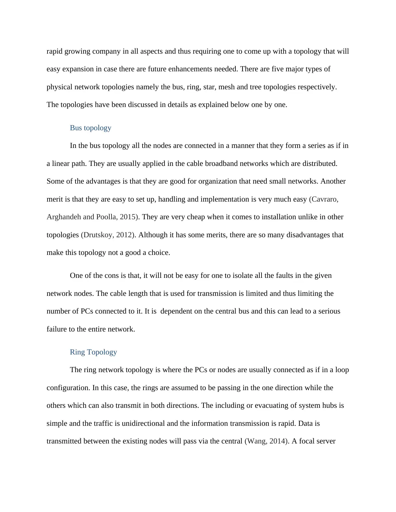
Bus topology
In the bus topology all the nodes are connected in a manner that they form a series as if in
a linear path. They are usually applied in the cable broadband networks which are distributed.
Some of the advantages is that they are good for organization that need small networks. Another
merit is that they are easy to set up, handling and implementation is very much easy (Cavraro,
Arghandeh and Poolla, 2015). They are very cheap when it comes to installation unlike in other
topologies (Drutskoy, 2012). Although it has some merits, there are so many disadvantages that
make this topology not a good a choice.
One of the cons is that, it will not be easy for one to isolate all the faults in the given
network nodes. The cable length that is used for transmission is limited and thus limiting the
number of PCs connected to it. It is dependent on the central bus and this can lead to a serious
failure to the entire network.
Ring Topology
The ring network topology is where the PCs or nodes are usually connected as if in a loop
configuration. In this case, the rings are assumed to be passing in the one direction while the
others which can also transmit in both directions. The including or evacuating of system hubs is
simple and the traffic is unidirectional and the information transmission is rapid. Data is
transmitted between the existing nodes will pass via the central (Wang, 2014). A focal server
easy expansion in case there are future enhancements needed. There are five major types of
physical network topologies namely the bus, ring, star, mesh and tree topologies respectively.
The topologies have been discussed in details as explained below one by one.
Bus topology
In the bus topology all the nodes are connected in a manner that they form a series as if in
a linear path. They are usually applied in the cable broadband networks which are distributed.
Some of the advantages is that they are good for organization that need small networks. Another
merit is that they are easy to set up, handling and implementation is very much easy (Cavraro,
Arghandeh and Poolla, 2015). They are very cheap when it comes to installation unlike in other
topologies (Drutskoy, 2012). Although it has some merits, there are so many disadvantages that
make this topology not a good a choice.
One of the cons is that, it will not be easy for one to isolate all the faults in the given
network nodes. The cable length that is used for transmission is limited and thus limiting the
number of PCs connected to it. It is dependent on the central bus and this can lead to a serious
failure to the entire network.
Ring Topology
The ring network topology is where the PCs or nodes are usually connected as if in a loop
configuration. In this case, the rings are assumed to be passing in the one direction while the
others which can also transmit in both directions. The including or evacuating of system hubs is
simple and the traffic is unidirectional and the information transmission is rapid. Data is
transmitted between the existing nodes will pass via the central (Wang, 2014). A focal server
⊘ This is a preview!⊘
Do you want full access?
Subscribe today to unlock all pages.
Trusted by 1+ million students worldwide
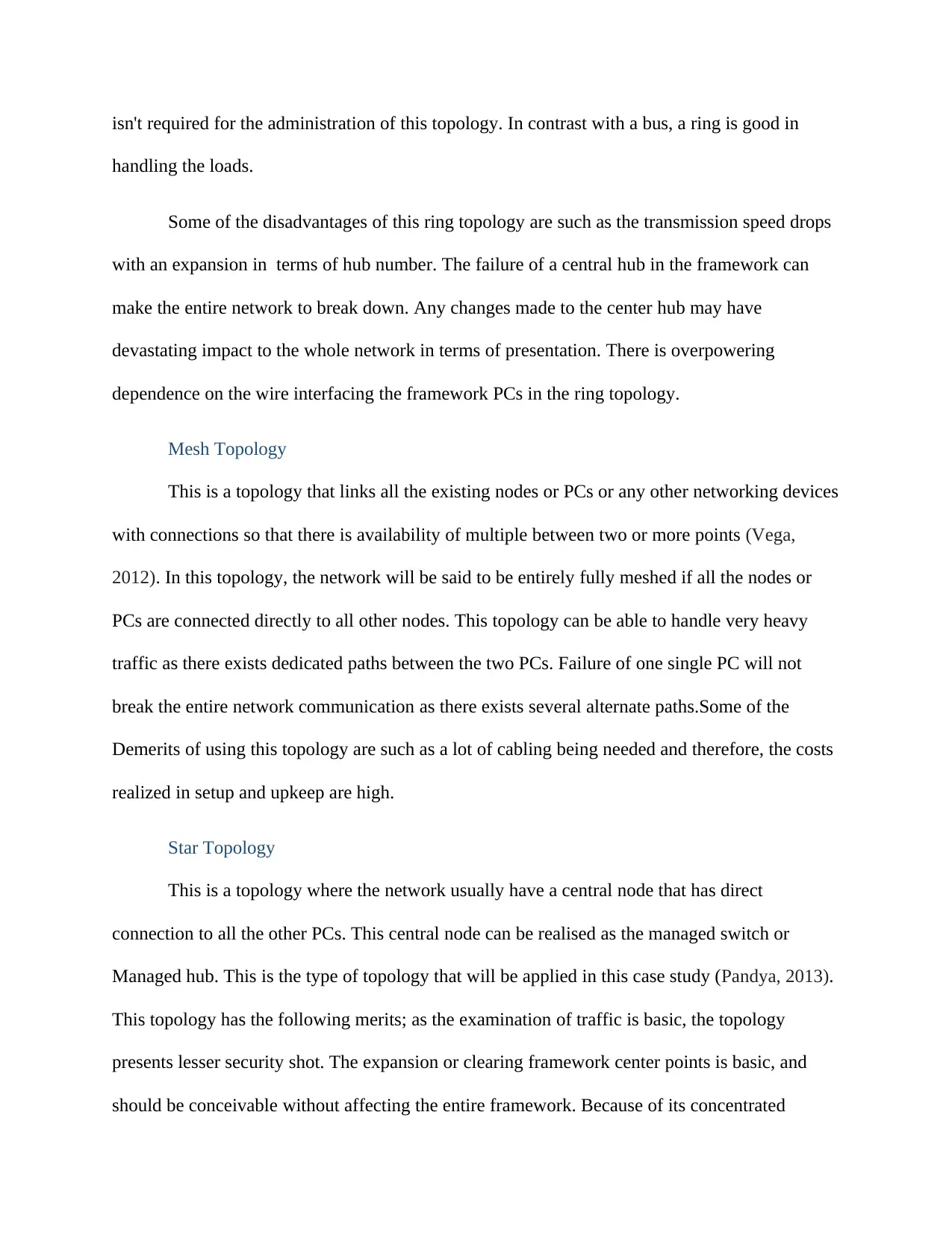
isn't required for the administration of this topology. In contrast with a bus, a ring is good in
handling the loads.
Some of the disadvantages of this ring topology are such as the transmission speed drops
with an expansion in terms of hub number. The failure of a central hub in the framework can
make the entire network to break down. Any changes made to the center hub may have
devastating impact to the whole network in terms of presentation. There is overpowering
dependence on the wire interfacing the framework PCs in the ring topology.
Mesh Topology
This is a topology that links all the existing nodes or PCs or any other networking devices
with connections so that there is availability of multiple between two or more points (Vega,
2012). In this topology, the network will be said to be entirely fully meshed if all the nodes or
PCs are connected directly to all other nodes. This topology can be able to handle very heavy
traffic as there exists dedicated paths between the two PCs. Failure of one single PC will not
break the entire network communication as there exists several alternate paths.Some of the
Demerits of using this topology are such as a lot of cabling being needed and therefore, the costs
realized in setup and upkeep are high.
Star Topology
This is a topology where the network usually have a central node that has direct
connection to all the other PCs. This central node can be realised as the managed switch or
Managed hub. This is the type of topology that will be applied in this case study (Pandya, 2013).
This topology has the following merits; as the examination of traffic is basic, the topology
presents lesser security shot. The expansion or clearing framework center points is basic, and
should be conceivable without affecting the entire framework. Because of its concentrated
Paraphrase This Document
Need a fresh take? Get an instant paraphrase of this document with our AI Paraphraser
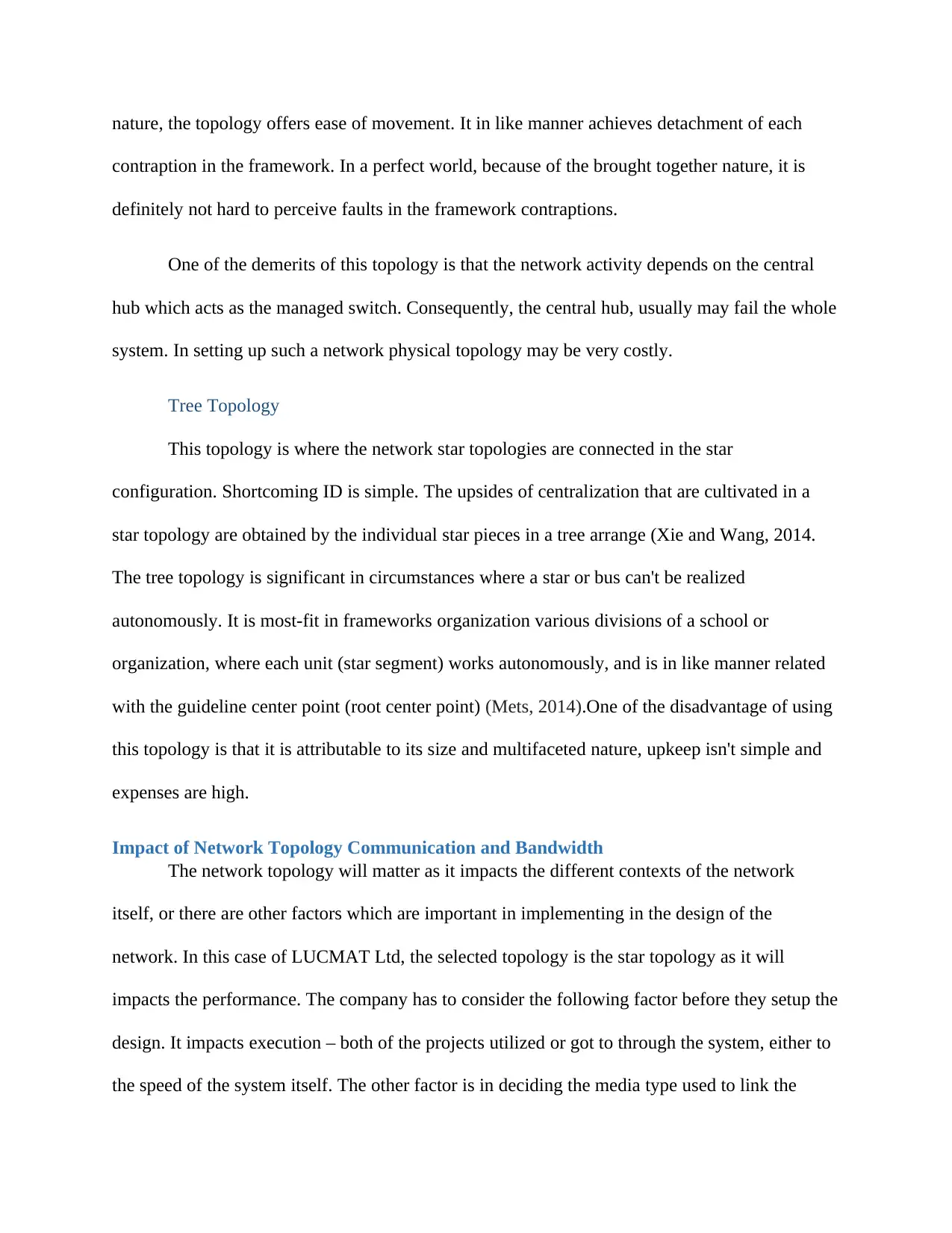
nature, the topology offers ease of movement. It in like manner achieves detachment of each
contraption in the framework. In a perfect world, because of the brought together nature, it is
definitely not hard to perceive faults in the framework contraptions.
One of the demerits of this topology is that the network activity depends on the central
hub which acts as the managed switch. Consequently, the central hub, usually may fail the whole
system. In setting up such a network physical topology may be very costly.
Tree Topology
This topology is where the network star topologies are connected in the star
configuration. Shortcoming ID is simple. The upsides of centralization that are cultivated in a
star topology are obtained by the individual star pieces in a tree arrange (Xie and Wang, 2014.
The tree topology is significant in circumstances where a star or bus can't be realized
autonomously. It is most-fit in frameworks organization various divisions of a school or
organization, where each unit (star segment) works autonomously, and is in like manner related
with the guideline center point (root center point) (Mets, 2014).One of the disadvantage of using
this topology is that it is attributable to its size and multifaceted nature, upkeep isn't simple and
expenses are high.
Impact of Network Topology Communication and Bandwidth
The network topology will matter as it impacts the different contexts of the network
itself, or there are other factors which are important in implementing in the design of the
network. In this case of LUCMAT Ltd, the selected topology is the star topology as it will
impacts the performance. The company has to consider the following factor before they setup the
design. It impacts execution – both of the projects utilized or got to through the system, either to
the speed of the system itself. The other factor is in deciding the media type used to link the
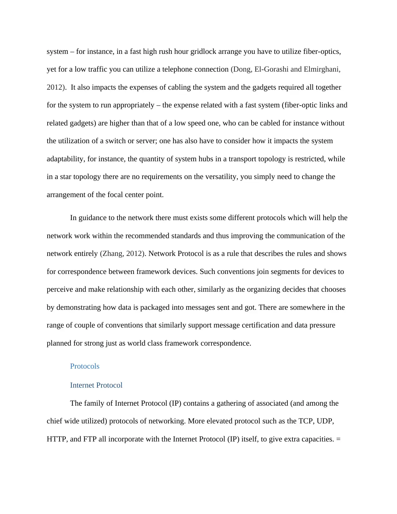
system – for instance, in a fast high rush hour gridlock arrange you have to utilize fiber-optics,
yet for a low traffic you can utilize a telephone connection (Dong, El-Gorashi and Elmirghani,
2012). It also impacts the expenses of cabling the system and the gadgets required all together
for the system to run appropriately – the expense related with a fast system (fiber-optic links and
related gadgets) are higher than that of a low speed one, who can be cabled for instance without
the utilization of a switch or server; one has also have to consider how it impacts the system
adaptability, for instance, the quantity of system hubs in a transport topology is restricted, while
in a star topology there are no requirements on the versatility, you simply need to change the
arrangement of the focal center point.
In guidance to the network there must exists some different protocols which will help the
network work within the recommended standards and thus improving the communication of the
network entirely (Zhang, 2012). Network Protocol is as a rule that describes the rules and shows
for correspondence between framework devices. Such conventions join segments for devices to
perceive and make relationship with each other, similarly as the organizing decides that chooses
by demonstrating how data is packaged into messages sent and got. There are somewhere in the
range of couple of conventions that similarly support message certification and data pressure
planned for strong just as world class framework correspondence.
Protocols
Internet Protocol
The family of Internet Protocol (IP) contains a gathering of associated (and among the
chief wide utilized) protocols of networking. More elevated protocol such as the TCP, UDP,
HTTP, and FTP all incorporate with the Internet Protocol (IP) itself, to give extra capacities. =
⊘ This is a preview!⊘
Do you want full access?
Subscribe today to unlock all pages.
Trusted by 1+ million students worldwide
Transmission Control Protocol (TCP)
This is used hand in hand with the internet protocol which are considered to be the two
distinct computer network protocols. They are applied together as TCP/IP as they have the
standard terminology in terms of the protocol suites (Davidson, 2012). TCP/IP in this case
usually applies the network communications in which the TCP transport is utilized to convey
information crosswise over IP systems.
Wireless Network Protocols
These are such protocols used to in the wireless environments and thus they have become
common and much popular in the current era (Petite, 2016). Most of these network protocols
uses the wireless network which indeed supports the mobile devices and solving the problems
such as the data rates of the variables and the security of the network.
OSI Model
This is a seven-layered methodology general worldview for examining or depicting how
PCs communicate with one another over a system (Bora, Singh and Arsalan, 2014). This way to
deal with information transmission isolates the different activities up into a particular
arrangement of activities on each layer. The OSI model was initially framed as a standard plan
for structure arrange frameworks thus, a few across the board organize advancements today
reflect the layered style of OSI.
Selected Physical Network Topology.
In this case of LUCMAT Ltd, the best topology that will meet all the required
specifications and needs is the star topology. However, the cost is very high, there is use of the
scalable high capacity managed switch. Another reason for its selection is that, it can handle
traffic loads at high speeds and also there is less security vulnerabilities and risks (Zhang, 2013).
Paraphrase This Document
Need a fresh take? Get an instant paraphrase of this document with our AI Paraphraser
Another reason for its consideration is that it has some simplicity in its operation and much more
maintenances as the scalability is exceptional.
Networking Devices and Operations
In this case, the idea is to give an explanation of the networking devices that will be
applied in the LUCMAT Ltd network design. There are many networking devices depending on
their functionalities and in this concept they have been applied widely as the network has
majored much on flexibility, security, performance and much more security. In this case, these
means a hierarchical diagram will need to be put in place so that this network design will be
successful. Some of the applied network devices are routers, switches, hub, NIC among others
as explained below with all their respective operations.
Hub
This is a devices that is usually applied for connecting the PCs in a single Local Area
Network. It usually used to send data signals to all the ports except on the one which the signal
has just arrived from so that it does not have to interfere with the signal.
Router
A router is a layer three gadget which sends information parcels starting with one system
portion then onto the next dependent on their destination address. So as to do this, the switch
tracks the way that parcels can utilize when they move over that arrange. Those records are kept
in a database table called a routing table.
Switch
Information signals are designed in edges on layer two, and when a switch gets a casing,
it checks the Frame Checksum Sequence (FCS) field in it, and procedure the casing just on the
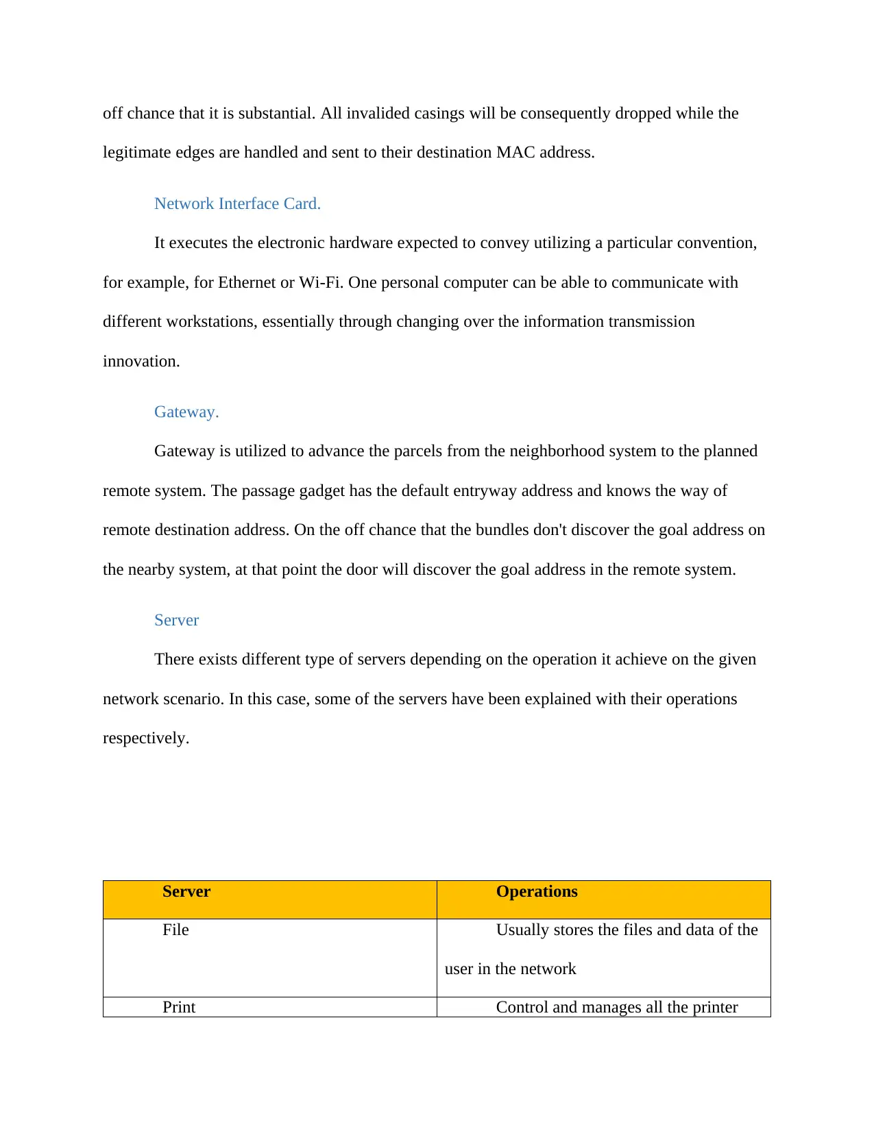
off chance that it is substantial. All invalided casings will be consequently dropped while the
legitimate edges are handled and sent to their destination MAC address.
Network Interface Card.
It executes the electronic hardware expected to convey utilizing a particular convention,
for example, for Ethernet or Wi-Fi. One personal computer can be able to communicate with
different workstations, essentially through changing over the information transmission
innovation.
Gateway.
Gateway is utilized to advance the parcels from the neighborhood system to the planned
remote system. The passage gadget has the default entryway address and knows the way of
remote destination address. On the off chance that the bundles don't discover the goal address on
the nearby system, at that point the door will discover the goal address in the remote system.
Server
There exists different type of servers depending on the operation it achieve on the given
network scenario. In this case, some of the servers have been explained with their operations
respectively.
Server Operations
File Usually stores the files and data of the
user in the network
Print Control and manages all the printer
⊘ This is a preview!⊘
Do you want full access?
Subscribe today to unlock all pages.
Trusted by 1+ million students worldwide
1 out of 32
Related Documents


Your All-in-One AI-Powered Toolkit for Academic Success.
+13062052269
info@desklib.com
Available 24*7 on WhatsApp / Email
![[object Object]](/_next/static/media/star-bottom.7253800d.svg)
Unlock your academic potential
Copyright © 2020–2026 A2Z Services. All Rights Reserved. Developed and managed by ZUCOL.