ICT106 Report: Network Design Proposal for XYZ Company Branches
VerifiedAdded on 2022/08/19
|17
|1770
|12
Report
AI Summary
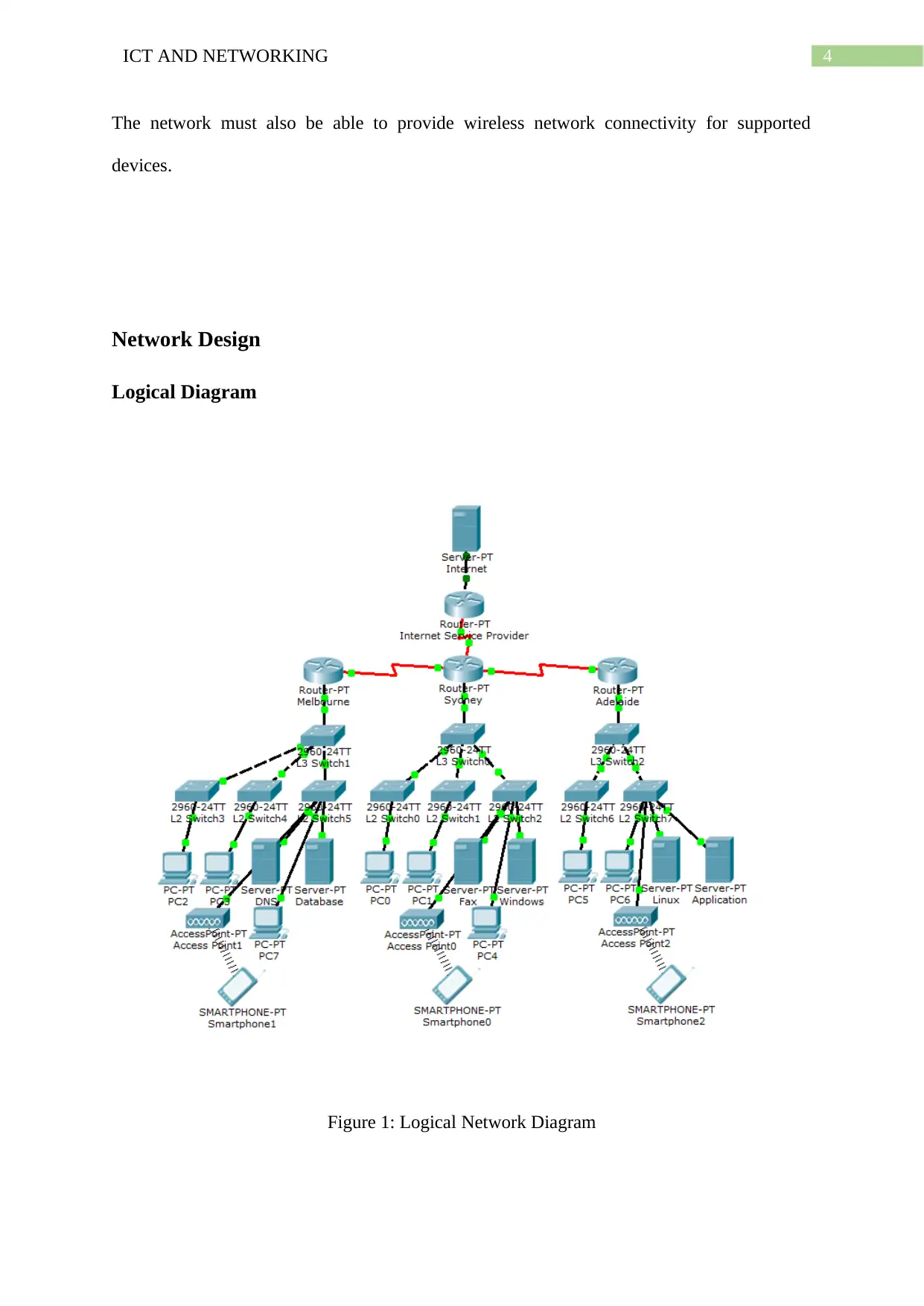
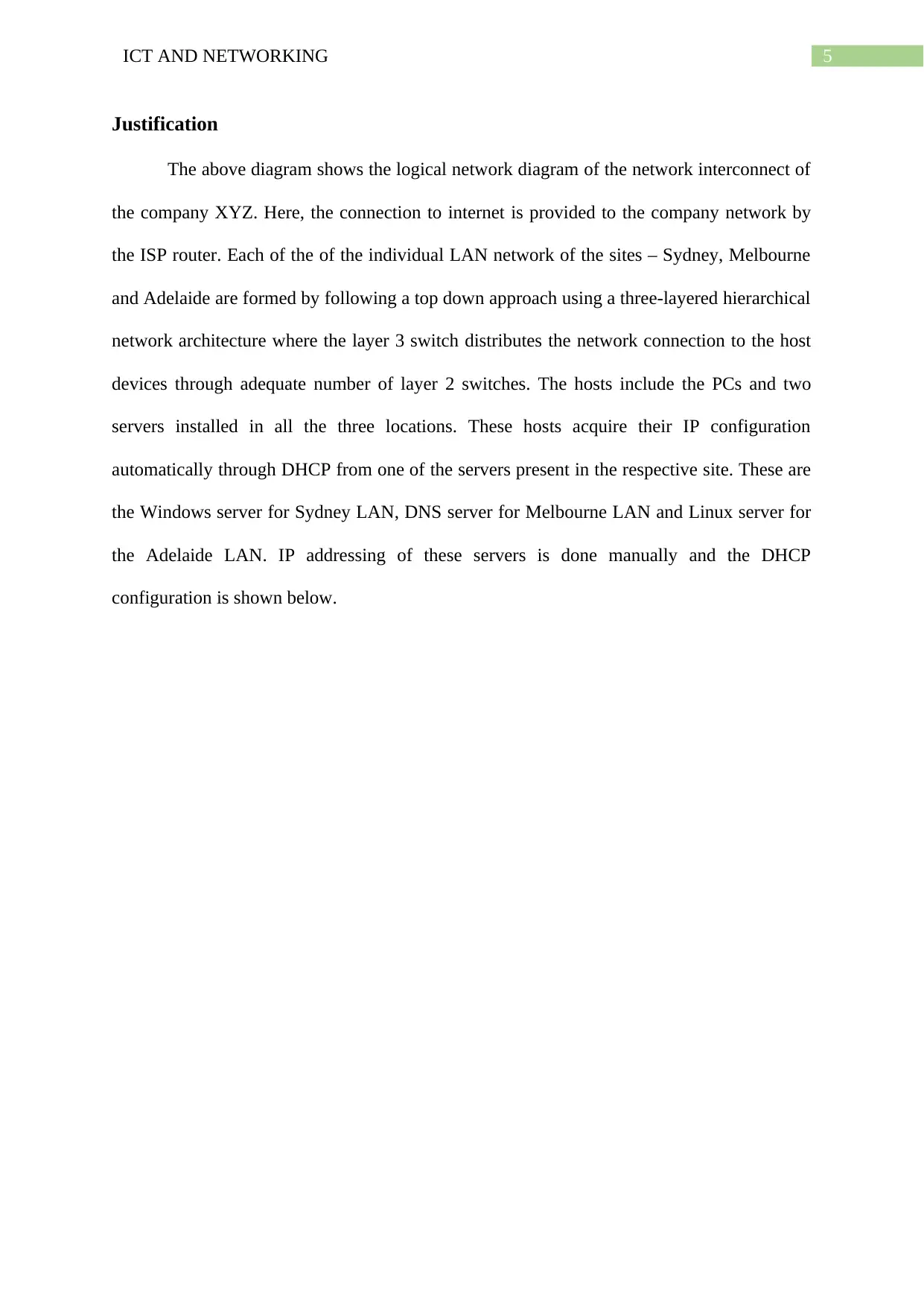
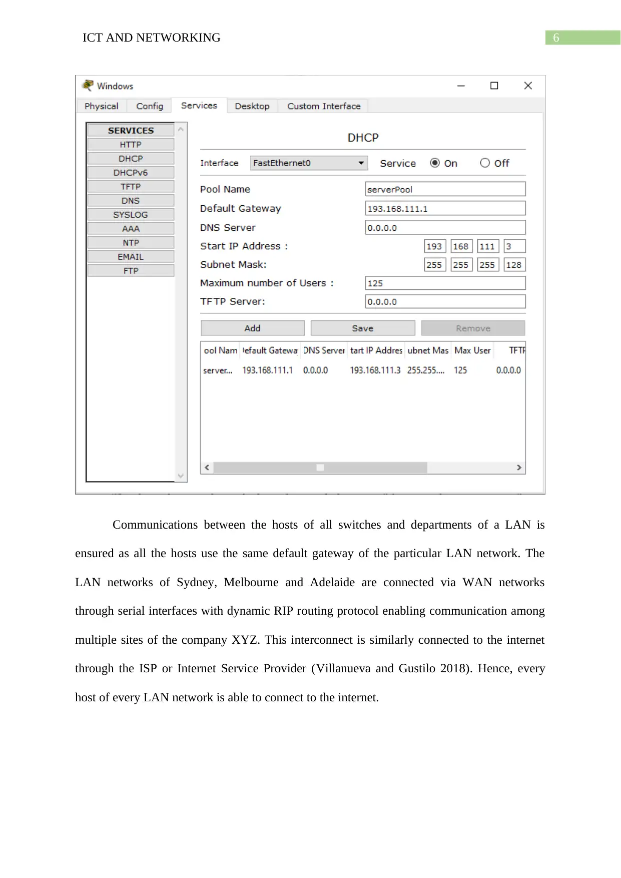
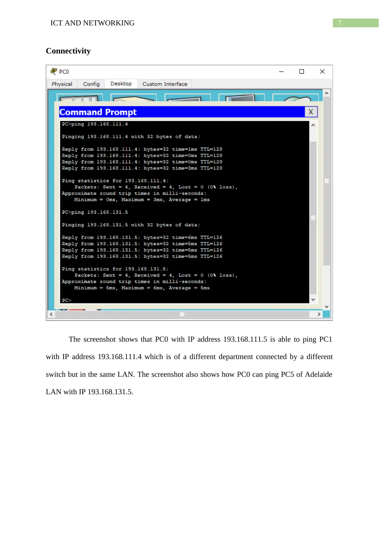
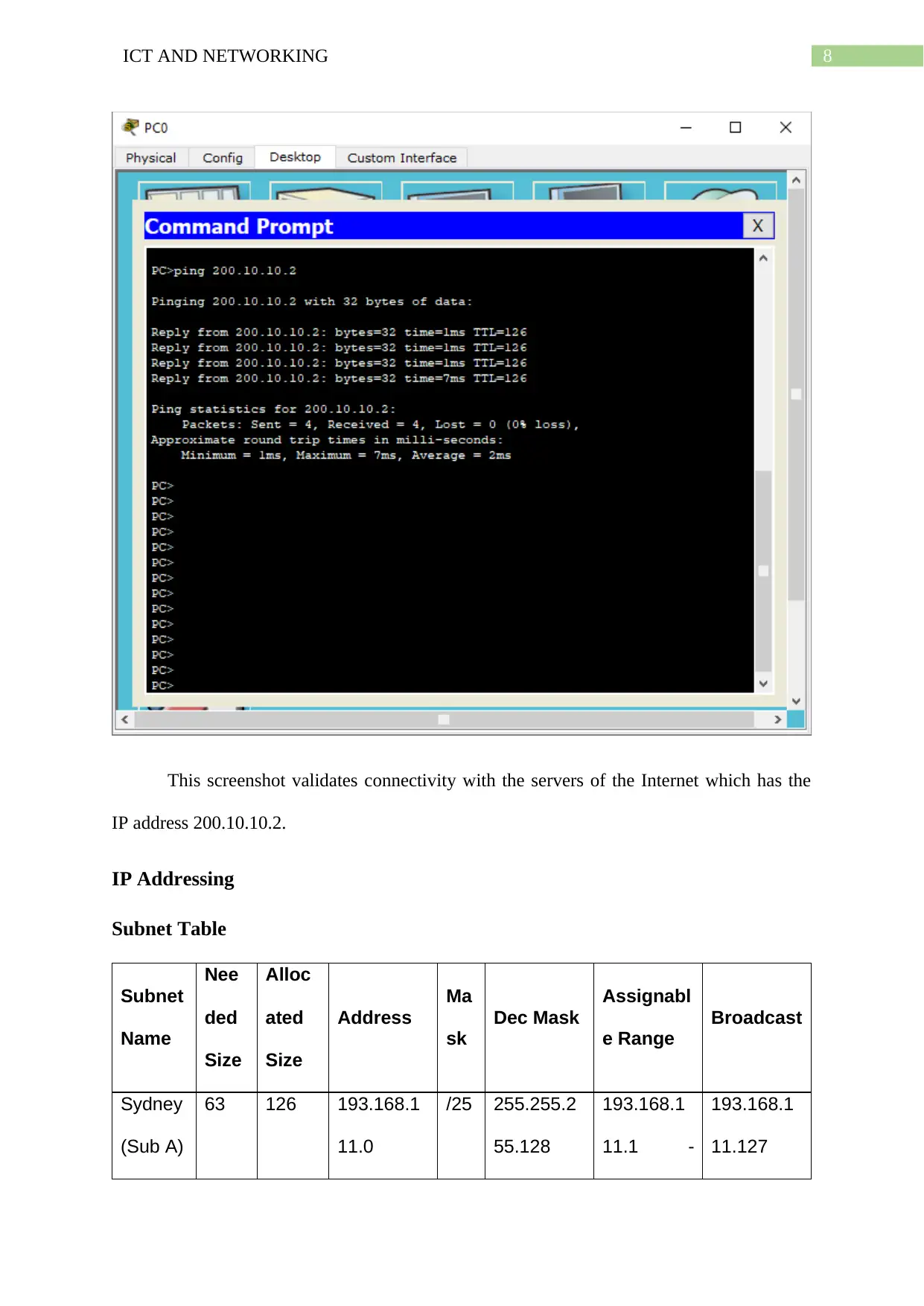
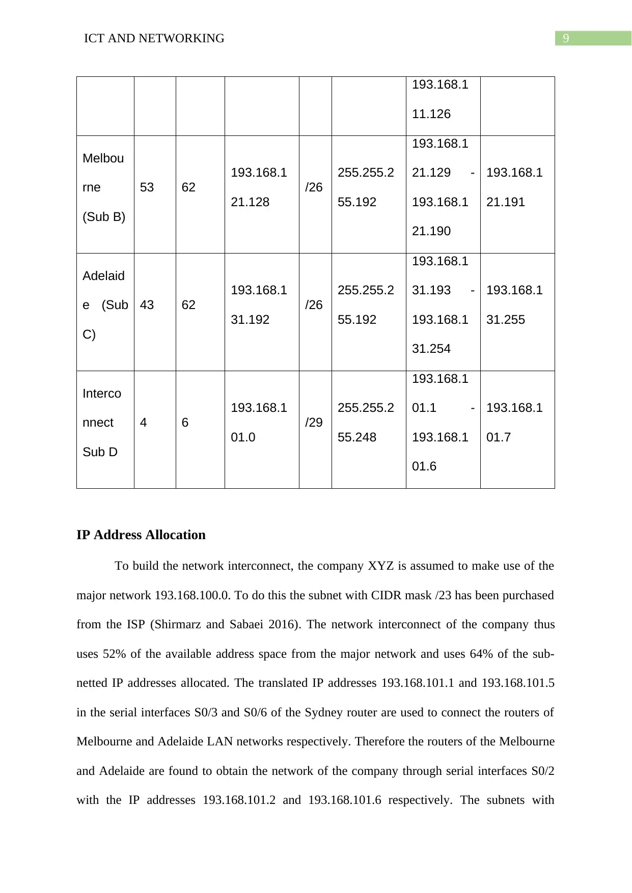
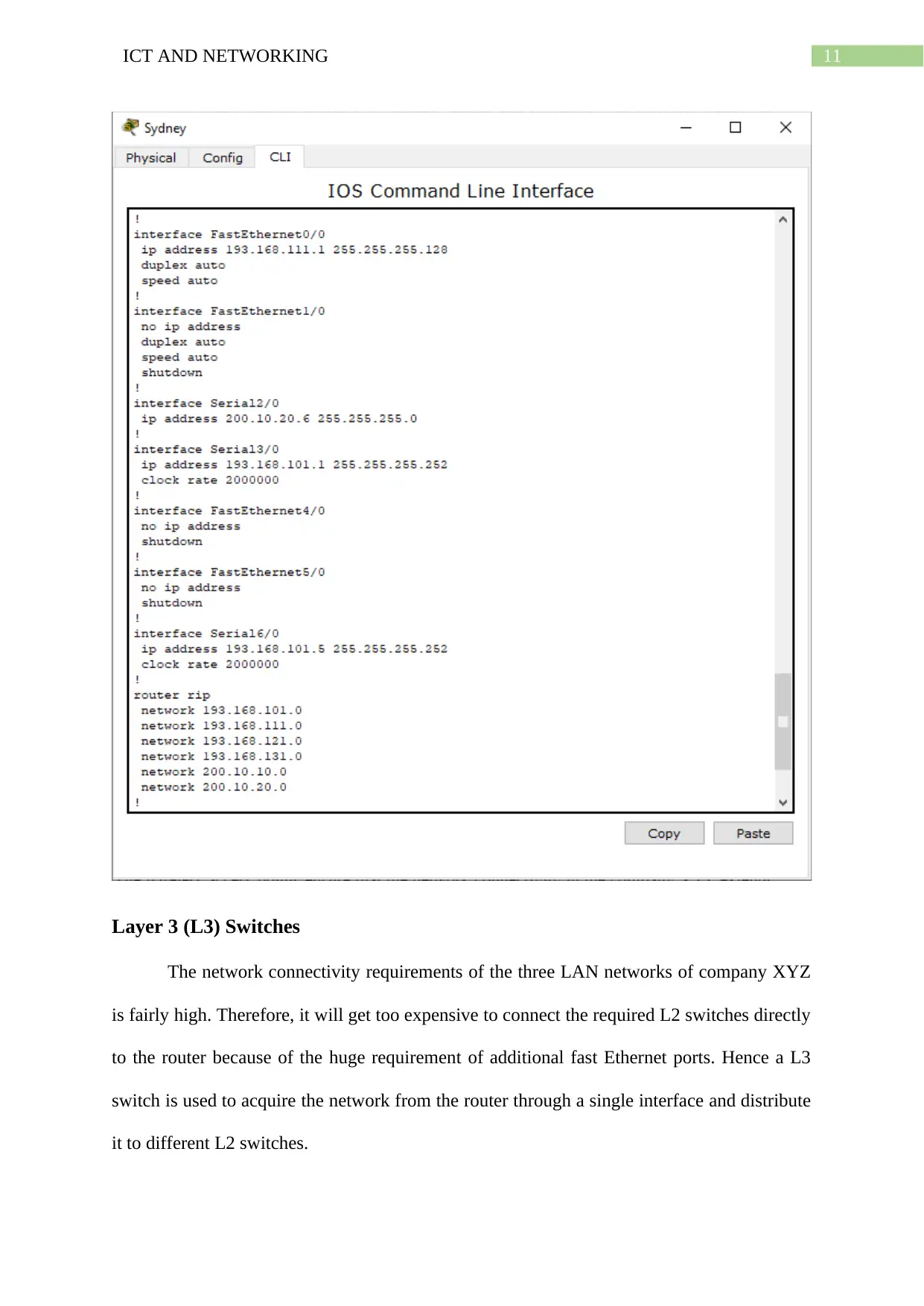
This report proposes a network design for XYZ Company, which has branches in Sydney, Melbourne, and Adelaide, focusing on enabling effective communication through Information and Communications Technology (ICT). The design incorporates a three-layered hierarchical network architecture using Cisco Packet Tracer, ensuring connectivity between hosts within each LAN and across different branches via WAN networks with dynamic RIP routing. The report details the IP addressing scheme, including subnet tables with network addresses, broadcast addresses, and IP ranges. It also discusses the selection and configuration of networking hardware, such as routers, Layer 3 switches, Layer 2 switches, and wireless access points, to support both wired and wireless connectivity. The proposed network ensures that hosts from different departments within a LAN can communicate with each other and with other branches and the Internet, validated by ping tests. The document concludes by emphasizing the importance of ICT in facilitating organizational communications.

Running head: ICT AND NETWORKING
ICT and Networking
Name of the Student
Name of the University
Author Note
ICT and Networking
Name of the Student
Name of the University
Author Note
Paraphrase This Document
Need a fresh take? Get an instant paraphrase of this document with our AI Paraphraser

1ICT AND NETWORKING
Executive Summary
Information Communications Technology or ICT plays an important role in enabling
communications within an organization. This report proposes a network design for a
company that has branches in three different cities in Australia. The proposed network
ensures that the hosts from different departments of a LAN network can communicate with
each other as also communicate with other branches and the Internet. After validating this the
report is to present the IP addressing scheme and then talk about network devices. Then the
report ends with concluding notes.

2ICT AND NETWORKING
Table of Contents
Introduction................................................................................................................................3
Requirements..............................................................................................................................3
Network Design.........................................................................................................................4
Logical Diagram.....................................................................................................................4
Justification............................................................................................................................4
Connectivity...........................................................................................................................6
IP Addressing.........................................................................................................................7
Subnet Table...........................................................................................................................7
IP Address Allocation............................................................................................................8
Networking Hardware................................................................................................................9
Routers...................................................................................................................................9
Layer 3 (L3) Switches..........................................................................................................10
Layer 2 (L2) Switches..........................................................................................................11
Wireless Access Points........................................................................................................11
Conclusion................................................................................................................................13
Bibliography.............................................................................................................................14
⊘ This is a preview!⊘
Do you want full access?
Subscribe today to unlock all pages.

Trusted by 1+ million students worldwide

3ICT AND NETWORKING
Introduction
The following report tries to show the importance of Information Communications
Technology or ICT when it comes to communications within organizations (Habibullah,
Rondeau and Georges 2018). This report begins by listing the different network requirements
and then elaborates the proposed network with a logical network diagram drawn in Cisco
Packet Tracer. Then the report explains how the network ensures connectivity among the
hosts and with the Internet. After that the different subnets get listed along with their
respective network addresses, broadcasts, mask and IP ranges. Following that the IP
addressing scheme is explained. Next the different networking hardware devices are
discussed and the wireless connectivity is shown. After this the report ends with concluding
notes.
Requirements
The company XYZ needs to build a network interconnect between its branches in Sydney,
Melbourne and Adelaide.
The company must purchase appropriate major network and mask to be able to allocate
adequate range of IP addresses for the respective subnets.
The branch at Sydney is to use Subnet A and operate 63 hosts including 60 PCs and 2 servers
namely Windows and Fax servers.
The Melbourne branch needs to use Subnet B and provide connections to 53 hosts including
50 PCs and 2 servers namely DNS and Database servers.
The Adelaide is to provide IP address made available from Subnet C to 43 hosts including 40
PCs and 2 servers namely Linux and Applications servers.
Paraphrase This Document
Need a fresh take? Get an instant paraphrase of this document with our AI Paraphraser

4ICT AND NETWORKING
The network must also be able to provide wireless network connectivity for supported
devices.
Network Design
Logical Diagram
Figure 1: Logical Network Diagram
The network must also be able to provide wireless network connectivity for supported
devices.
Network Design
Logical Diagram
Figure 1: Logical Network Diagram

5ICT AND NETWORKING
Justification
The above diagram shows the logical network diagram of the network interconnect of
the company XYZ. Here, the connection to internet is provided to the company network by
the ISP router. Each of the of the individual LAN network of the sites – Sydney, Melbourne
and Adelaide are formed by following a top down approach using a three-layered hierarchical
network architecture where the layer 3 switch distributes the network connection to the host
devices through adequate number of layer 2 switches. The hosts include the PCs and two
servers installed in all the three locations. These hosts acquire their IP configuration
automatically through DHCP from one of the servers present in the respective site. These are
the Windows server for Sydney LAN, DNS server for Melbourne LAN and Linux server for
the Adelaide LAN. IP addressing of these servers is done manually and the DHCP
configuration is shown below.
⊘ This is a preview!⊘
Do you want full access?
Subscribe today to unlock all pages.

Trusted by 1+ million students worldwide

6ICT AND NETWORKING
Communications between the hosts of all switches and departments of a LAN is
ensured as all the hosts use the same default gateway of the particular LAN network. The
LAN networks of Sydney, Melbourne and Adelaide are connected via WAN networks
through serial interfaces with dynamic RIP routing protocol enabling communication among
multiple sites of the company XYZ. This interconnect is similarly connected to the internet
through the ISP or Internet Service Provider (Villanueva and Gustilo 2018). Hence, every
host of every LAN network is able to connect to the internet.
Paraphrase This Document
Need a fresh take? Get an instant paraphrase of this document with our AI Paraphraser

7ICT AND NETWORKING
Connectivity
The screenshot shows that PC0 with IP address 193.168.111.5 is able to ping PC1
with IP address 193.168.111.4 which is of a different department connected by a different
switch but in the same LAN. The screenshot also shows how PC0 can ping PC5 of Adelaide
LAN with IP 193.168.131.5.
Connectivity
The screenshot shows that PC0 with IP address 193.168.111.5 is able to ping PC1
with IP address 193.168.111.4 which is of a different department connected by a different
switch but in the same LAN. The screenshot also shows how PC0 can ping PC5 of Adelaide
LAN with IP 193.168.131.5.

8ICT AND NETWORKING
This screenshot validates connectivity with the servers of the Internet which has the
IP address 200.10.10.2.
IP Addressing
Subnet Table
Subnet
Name
Nee
ded
Size
Alloc
ated
Size
Address
Ma
sk
Dec Mask
Assignabl
e Range
Broadcast
Sydney
(Sub A)
63 126 193.168.1
11.0
/25 255.255.2
55.128
193.168.1
11.1 -
193.168.1
11.127
⊘ This is a preview!⊘
Do you want full access?
Subscribe today to unlock all pages.

Trusted by 1+ million students worldwide

9ICT AND NETWORKING
193.168.1
11.126
Melbou
rne
(Sub B)
53 62
193.168.1
21.128
/26
255.255.2
55.192
193.168.1
21.129 -
193.168.1
21.190
193.168.1
21.191
Adelaid
e (Sub
C)
43 62
193.168.1
31.192
/26
255.255.2
55.192
193.168.1
31.193 -
193.168.1
31.254
193.168.1
31.255
Interco
nnect
Sub D
4 6
193.168.1
01.0
/29
255.255.2
55.248
193.168.1
01.1 -
193.168.1
01.6
193.168.1
01.7
IP Address Allocation
To build the network interconnect, the company XYZ is assumed to make use of the
major network 193.168.100.0. To do this the subnet with CIDR mask /23 has been purchased
from the ISP (Shirmarz and Sabaei 2016). The network interconnect of the company thus
uses 52% of the available address space from the major network and uses 64% of the sub-
netted IP addresses allocated. The translated IP addresses 193.168.101.1 and 193.168.101.5
in the serial interfaces S0/3 and S0/6 of the Sydney router are used to connect the routers of
Melbourne and Adelaide LAN networks respectively. Therefore the routers of the Melbourne
and Adelaide are found to obtain the network of the company through serial interfaces S0/2
with the IP addresses 193.168.101.2 and 193.168.101.6 respectively. The subnets with
193.168.1
11.126
Melbou
rne
(Sub B)
53 62
193.168.1
21.128
/26
255.255.2
55.192
193.168.1
21.129 -
193.168.1
21.190
193.168.1
21.191
Adelaid
e (Sub
C)
43 62
193.168.1
31.192
/26
255.255.2
55.192
193.168.1
31.193 -
193.168.1
31.254
193.168.1
31.255
Interco
nnect
Sub D
4 6
193.168.1
01.0
/29
255.255.2
55.248
193.168.1
01.1 -
193.168.1
01.6
193.168.1
01.7
IP Address Allocation
To build the network interconnect, the company XYZ is assumed to make use of the
major network 193.168.100.0. To do this the subnet with CIDR mask /23 has been purchased
from the ISP (Shirmarz and Sabaei 2016). The network interconnect of the company thus
uses 52% of the available address space from the major network and uses 64% of the sub-
netted IP addresses allocated. The translated IP addresses 193.168.101.1 and 193.168.101.5
in the serial interfaces S0/3 and S0/6 of the Sydney router are used to connect the routers of
Melbourne and Adelaide LAN networks respectively. Therefore the routers of the Melbourne
and Adelaide are found to obtain the network of the company through serial interfaces S0/2
with the IP addresses 193.168.101.2 and 193.168.101.6 respectively. The subnets with
Paraphrase This Document
Need a fresh take? Get an instant paraphrase of this document with our AI Paraphraser

10ICT AND NETWORKING
network addresses 193.168.111.0, 193.168.121.0 and 193.168.131.0 are used in the private
LAN networks of Sydney, Melbourne and Adelaide respectively.
Networking Hardware
Routers
The routers are the primary networking device that is enabling the effective routing of
the network from each network segment to another. The ISP router, the Sydney router, the
Melbourne router and the Adelaide router are connected over a WAN network through serial
interfaces by using the RIP dynamic routing protocol. The company routers then go on to
connect the host devices of their respective LAN networks through the fast Ethernet
interfaces. The configuration of the Sydney router is given in the next screenshot.

11ICT AND NETWORKING
Layer 3 (L3) Switches
The network connectivity requirements of the three LAN networks of company XYZ
is fairly high. Therefore, it will get too expensive to connect the required L2 switches directly
to the router because of the huge requirement of additional fast Ethernet ports. Hence a L3
switch is used to acquire the network from the router through a single interface and distribute
it to different L2 switches.
⊘ This is a preview!⊘
Do you want full access?
Subscribe today to unlock all pages.

Trusted by 1+ million students worldwide
1 out of 17
Related Documents

Your All-in-One AI-Powered Toolkit for Academic Success.
+13062052269
info@desklib.com
Available 24*7 on WhatsApp / Email
Unlock your academic potential
Copyright © 2020–2025 A2Z Services. All Rights Reserved. Developed and managed by ZUCOL.