Network Design and Analysis: Family Counts Charity (FCC) Project
VerifiedAdded on 2023/06/12
|29
|5615
|385
Report
AI Summary
This report details the network development for Family Counts Charity, an organization providing information, advice, advocacy, and legal representation. The report addresses the need for a secured and expanded network to improve security and efficiency. It includes five tasks covering network infrastructure and protocols, addressing schemes, security measures, network diagram and hardware component selection, and remote access solutions. Specific topics include cable requirements, comparisons of network devices (hubs, switches, wireless access points, routers), OSI model layer descriptions, IP addressing (private and public IPv4), DHCP and ARP explanations, default gateway and subnet mask configuration, IP routing tables, security considerations, network topology design, IPv4 address allocation, hardware component selection with pricing, remote access options, and justifications for solutions like Dropbox. The analysis aims to provide a comprehensive network solution tailored to the charity's needs. Desklib offers similar solved assignments and resources for students.
Running head: NETWORK ANALYSIS AND DESIGN
Network Analysis and Design
Name of Student:
Name of the University:
Author Note
Network Analysis and Design
Name of Student:
Name of the University:
Author Note
Paraphrase This Document
Need a fresh take? Get an instant paraphrase of this document with our AI Paraphraser
1
NETWORK ANALYSIS AND DESIGN
Table of Contents
Introduction......................................................................................................................................2
Task 1: Network Infrastructure and Protocols.................................................................................2
Cable requirement........................................................................................................................2
The comparison of Hub, Switch, wireless access point and Router............................................3
The OSI model has 7 layers and supports 2 running process in the network. the description
about the layers are provided below:...........................................................................................7
The protocols used by the 7 layers of the OSI model is provided below:...................................8
Task 2: Addressing..........................................................................................................................9
Network components addressing.................................................................................................9
Private IPv4 address and a public IPv4 address........................................................................10
DHCP explanation.....................................................................................................................11
ARP explanation........................................................................................................................12
Default Gateway and Subnet Mask...........................................................................................12
IP Routing Table........................................................................................................................13
Task 3: Security.............................................................................................................................13
Task 4: Diagram and explanation..................................................................................................14
Network Topology.....................................................................................................................14
IPv4 address allocation..............................................................................................................15
Selection of hardware components............................................................................................17
2
NETWORK ANALYSIS AND DESIGN
Prices of the recommended hardware........................................................................................17
Task 5: Remote access...................................................................................................................22
Remote access security..............................................................................................................22
Dropbox justification.................................................................................................................22
Impact of remote access on the system......................................................................................23
Bibliography..................................................................................................................................24
⊘ This is a preview!⊘
Do you want full access?
Subscribe today to unlock all pages.
Trusted by 1+ million students worldwide
3
NETWORK ANALYSIS AND DESIGN
Introduction
The reports deals with the details of the Family counts Charity network development. The
organization provides the clients with services like information, advice, advocacy and legal
representation. The company has expanded over the last 18 years since it was created and the
network of the company has also been expanding from the time of creation. However lately the
need for a secured network has developed in the organization and also the organization is
looking to expand the network and also set up a new network that would be improving the
security and efficiency of the network. The report contains description of 5 tasks that would be
required for the set of the network.
Task 1: Network Infrastructure and Protocols
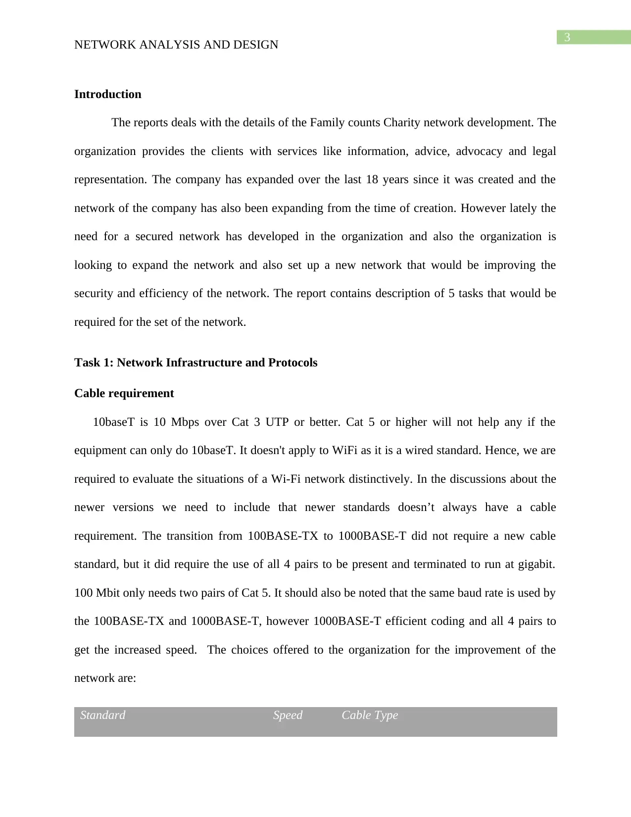
Cable requirement
10baseT is 10 Mbps over Cat 3 UTP or better. Cat 5 or higher will not help any if the
equipment can only do 10baseT. It doesn't apply to WiFi as it is a wired standard. Hence, we are
required to evaluate the situations of a Wi-Fi network distinctively. In the discussions about the
newer versions we need to include that newer standards doesn’t always have a cable
requirement. The transition from 100BASE-TX to 1000BASE-T did not require a new cable
standard, but it did require the use of all 4 pairs to be present and terminated to run at gigabit.
100 Mbit only needs two pairs of Cat 5. It should also be noted that the same baud rate is used by
the 100BASE-TX and 1000BASE-T, however 1000BASE-T efficient coding and all 4 pairs to
get the increased speed. The choices offered to the organization for the improvement of the
network are:
Standard Speed Cable Type
NETWORK ANALYSIS AND DESIGN
Introduction
The reports deals with the details of the Family counts Charity network development. The
organization provides the clients with services like information, advice, advocacy and legal
representation. The company has expanded over the last 18 years since it was created and the
network of the company has also been expanding from the time of creation. However lately the
need for a secured network has developed in the organization and also the organization is
looking to expand the network and also set up a new network that would be improving the
security and efficiency of the network. The report contains description of 5 tasks that would be
required for the set of the network.
Task 1: Network Infrastructure and Protocols
Cable requirement
10baseT is 10 Mbps over Cat 3 UTP or better. Cat 5 or higher will not help any if the
equipment can only do 10baseT. It doesn't apply to WiFi as it is a wired standard. Hence, we are
required to evaluate the situations of a Wi-Fi network distinctively. In the discussions about the
newer versions we need to include that newer standards doesn’t always have a cable
requirement. The transition from 100BASE-TX to 1000BASE-T did not require a new cable
standard, but it did require the use of all 4 pairs to be present and terminated to run at gigabit.
100 Mbit only needs two pairs of Cat 5. It should also be noted that the same baud rate is used by
the 100BASE-TX and 1000BASE-T, however 1000BASE-T efficient coding and all 4 pairs to
get the increased speed. The choices offered to the organization for the improvement of the
network are:
Standard Speed Cable Type
Paraphrase This Document
Need a fresh take? Get an instant paraphrase of this document with our AI Paraphraser
4
NETWORK ANALYSIS AND DESIGN
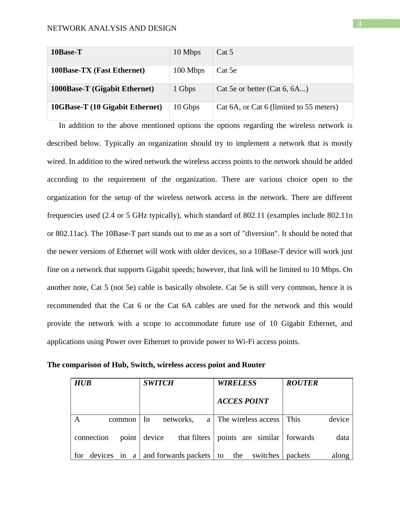
10Base-T 10 Mbps Cat 5
100Base-TX (Fast Ethernet) 100 Mbps Cat 5e
1000Base-T (Gigabit Ethernet) 1 Gbps Cat 5e or better (Cat 6, 6A...)
10GBase-T (10 Gigabit Ethernet) 10 Gbps Cat 6A, or Cat 6 (limited to 55 meters)
In addition to the above mentioned options the options regarding the wireless network is
described below. Typically an organization should try to implement a network that is mostly
wired. In addition to the wired network the wireless access points to the network should be added
according to the requirement of the organization. There are various choice open to the
organization for the setup of the wireless network access in the network. There are different
frequencies used (2.4 or 5 GHz typically), which standard of 802.11 (examples include 802.11n
or 802.11ac). The 10Base-T part stands out to me as a sort of "diversion". It should be noted that
the newer versions of Ethernet will work with older devices, so a 10Base-T device will work just
fine on a network that supports Gigabit speeds; however, that link will be limited to 10 Mbps. On
another note, Cat 5 (not 5e) cable is basically obsolete. Cat 5e is still very common, hence it is
recommended that the Cat 6 or the Cat 6A cables are used for the network and this would
provide the network with a scope to accommodate future use of 10 Gigabit Ethernet, and
applications using Power over Ethernet to provide power to Wi-Fi access points.
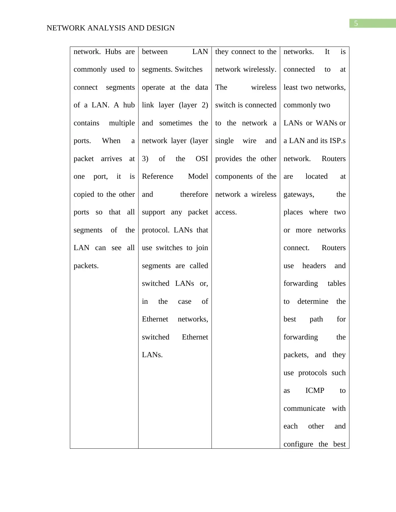
The comparison of Hub, Switch, wireless access point and Router
HUB SWITCH WIRELESS
ACCES POINT
ROUTER
A common
connection point
for devices in a
In networks, a
device that filters
and forwards packets
The wireless access
points are similar
to the switches
This device
forwards data
packets along
NETWORK ANALYSIS AND DESIGN
10Base-T 10 Mbps Cat 5
100Base-TX (Fast Ethernet) 100 Mbps Cat 5e
1000Base-T (Gigabit Ethernet) 1 Gbps Cat 5e or better (Cat 6, 6A...)
10GBase-T (10 Gigabit Ethernet) 10 Gbps Cat 6A, or Cat 6 (limited to 55 meters)
In addition to the above mentioned options the options regarding the wireless network is
described below. Typically an organization should try to implement a network that is mostly
wired. In addition to the wired network the wireless access points to the network should be added
according to the requirement of the organization. There are various choice open to the
organization for the setup of the wireless network access in the network. There are different
frequencies used (2.4 or 5 GHz typically), which standard of 802.11 (examples include 802.11n
or 802.11ac). The 10Base-T part stands out to me as a sort of "diversion". It should be noted that
the newer versions of Ethernet will work with older devices, so a 10Base-T device will work just
fine on a network that supports Gigabit speeds; however, that link will be limited to 10 Mbps. On
another note, Cat 5 (not 5e) cable is basically obsolete. Cat 5e is still very common, hence it is
recommended that the Cat 6 or the Cat 6A cables are used for the network and this would
provide the network with a scope to accommodate future use of 10 Gigabit Ethernet, and
applications using Power over Ethernet to provide power to Wi-Fi access points.
The comparison of Hub, Switch, wireless access point and Router
HUB SWITCH WIRELESS
ACCES POINT
ROUTER
A common
connection point
for devices in a
In networks, a
device that filters
and forwards packets
The wireless access
points are similar
to the switches
This device
forwards data
packets along
5
NETWORK ANALYSIS AND DESIGN
network. Hubs are
commonly used to
connect segments
of a LAN. A hub
contains multiple
ports. When a
packet arrives at
one port, it is
copied to the other
ports so that all
segments of the
LAN can see all
packets.
between LAN
segments. Switches
operate at the data
link layer (layer 2)
and sometimes the
network layer (layer
3) of the OSI
Reference Model
and therefore
support any packet
protocol. LANs that
use switches to join
segments are called
switched LANs or,
in the case of
Ethernet networks,
switched Ethernet
LANs.
they connect to the
network wirelessly.
The wireless
switch is connected
to the network a
single wire and
provides the other
components of the
network a wireless
access.
networks. It is
connected to at
least two networks,
commonly two
LANs or WANs or
a LAN and its ISP.s
network. Routers
are located at
gateways, the
places where two
or more networks
connect. Routers
use headers and
forwarding tables
to determine the
best path for
forwarding the
packets, and they
use protocols such
as ICMP to
communicate with
each other and
configure the best
⊘ This is a preview!⊘
Do you want full access?
Subscribe today to unlock all pages.
Trusted by 1+ million students worldwide
6
NETWORK ANALYSIS AND DESIGN
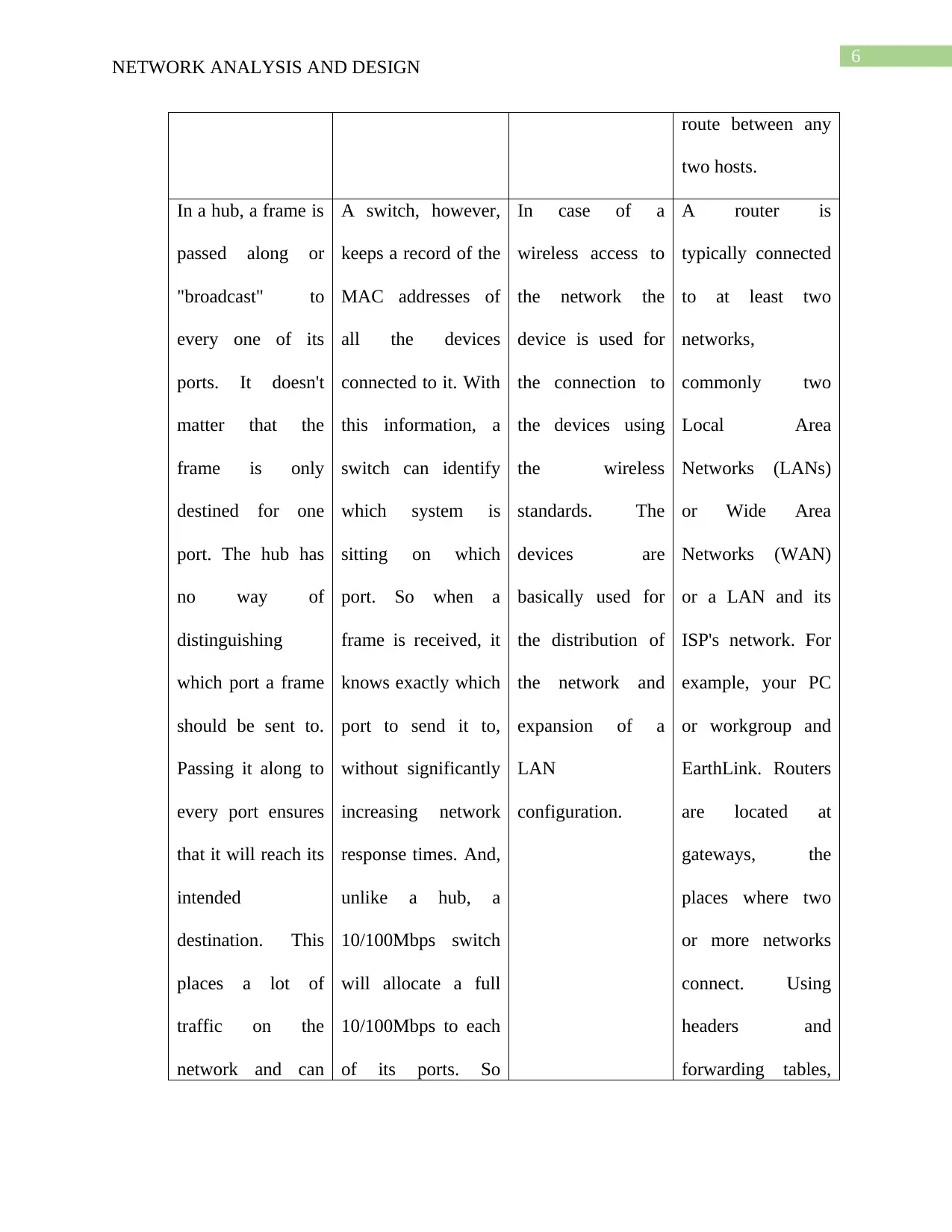
route between any
two hosts.
In a hub, a frame is
passed along or
"broadcast" to
every one of its
ports. It doesn't
matter that the
frame is only
destined for one
port. The hub has
no way of
distinguishing
which port a frame
should be sent to.
Passing it along to
every port ensures
that it will reach its
intended
destination. This
places a lot of
traffic on the
network and can
A switch, however,
keeps a record of the
MAC addresses of
all the devices
connected to it. With
this information, a
switch can identify
which system is
sitting on which
port. So when a
frame is received, it
knows exactly which
port to send it to,
without significantly
increasing network
response times. And,
unlike a hub, a
10/100Mbps switch
will allocate a full
10/100Mbps to each
of its ports. So
In case of a
wireless access to
the network the
device is used for
the connection to
the devices using
the wireless
standards. The
devices are
basically used for
the distribution of
the network and
expansion of a
LAN
configuration.
A router is
typically connected
to at least two
networks,
commonly two
Local Area
Networks (LANs)
or Wide Area
Networks (WAN)
or a LAN and its
ISP's network. For
example, your PC
or workgroup and
EarthLink. Routers
are located at
gateways, the
places where two
or more networks
connect. Using
headers and
forwarding tables,
NETWORK ANALYSIS AND DESIGN
route between any
two hosts.
In a hub, a frame is
passed along or
"broadcast" to
every one of its
ports. It doesn't
matter that the
frame is only
destined for one
port. The hub has
no way of
distinguishing
which port a frame
should be sent to.
Passing it along to
every port ensures
that it will reach its
intended
destination. This
places a lot of
traffic on the
network and can
A switch, however,
keeps a record of the
MAC addresses of
all the devices
connected to it. With
this information, a
switch can identify
which system is
sitting on which
port. So when a
frame is received, it
knows exactly which
port to send it to,
without significantly
increasing network
response times. And,
unlike a hub, a
10/100Mbps switch
will allocate a full
10/100Mbps to each
of its ports. So
In case of a
wireless access to
the network the
device is used for
the connection to
the devices using
the wireless
standards. The
devices are
basically used for
the distribution of
the network and
expansion of a
LAN
configuration.
A router is
typically connected
to at least two
networks,
commonly two
Local Area
Networks (LANs)
or Wide Area
Networks (WAN)
or a LAN and its
ISP's network. For
example, your PC
or workgroup and
EarthLink. Routers
are located at
gateways, the
places where two
or more networks
connect. Using
headers and
forwarding tables,
Paraphrase This Document
Need a fresh take? Get an instant paraphrase of this document with our AI Paraphraser
7
NETWORK ANALYSIS AND DESIGN
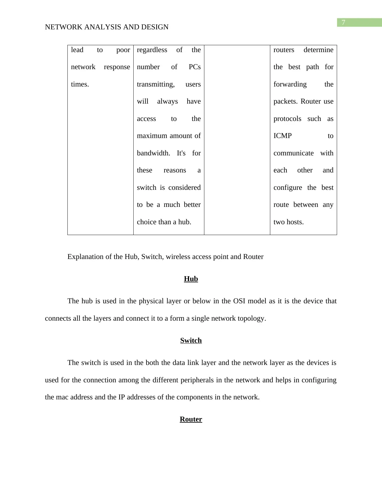
lead to poor
network response
times.
regardless of the
number of PCs
transmitting, users
will always have
access to the
maximum amount of
bandwidth. It's for
these reasons a
switch is considered
to be a much better
choice than a hub.
routers determine
the best path for
forwarding the
packets. Router use
protocols such as
ICMP to
communicate with
each other and
configure the best
route between any
two hosts.
Explanation of the Hub, Switch, wireless access point and Router
Hub
The hub is used in the physical layer or below in the OSI model as it is the device that
connects all the layers and connect it to a form a single network topology.
Switch
The switch is used in the both the data link layer and the network layer as the devices is
used for the connection among the different peripherals in the network and helps in configuring
the mac address and the IP addresses of the components in the network.
Router
NETWORK ANALYSIS AND DESIGN
lead to poor
network response
times.
regardless of the
number of PCs
transmitting, users
will always have
access to the
maximum amount of
bandwidth. It's for
these reasons a
switch is considered
to be a much better
choice than a hub.
routers determine
the best path for
forwarding the
packets. Router use
protocols such as
ICMP to
communicate with
each other and
configure the best
route between any
two hosts.
Explanation of the Hub, Switch, wireless access point and Router
Hub
The hub is used in the physical layer or below in the OSI model as it is the device that
connects all the layers and connect it to a form a single network topology.
Switch
The switch is used in the both the data link layer and the network layer as the devices is
used for the connection among the different peripherals in the network and helps in configuring
the mac address and the IP addresses of the components in the network.
Router
8
NETWORK ANALYSIS AND DESIGN
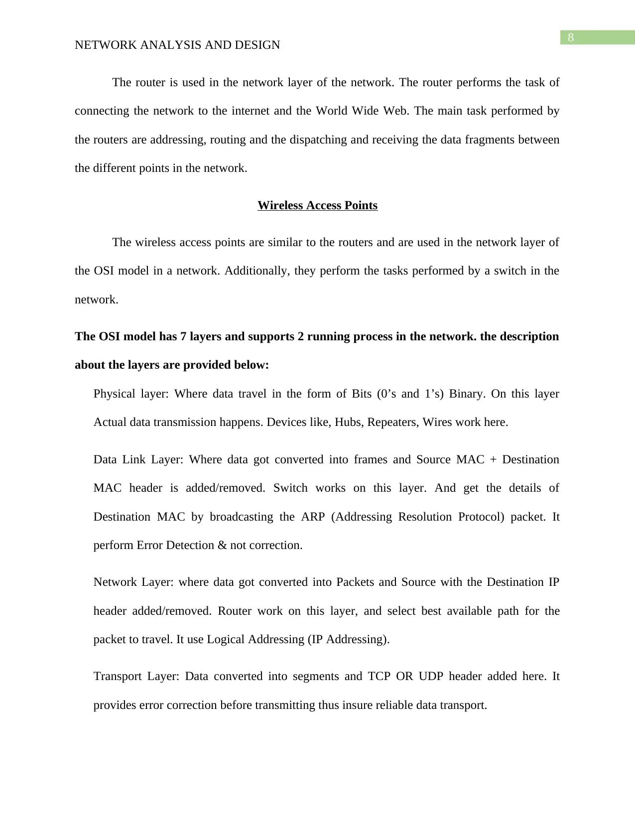
The router is used in the network layer of the network. The router performs the task of
connecting the network to the internet and the World Wide Web. The main task performed by
the routers are addressing, routing and the dispatching and receiving the data fragments between
the different points in the network.
Wireless Access Points
The wireless access points are similar to the routers and are used in the network layer of
the OSI model in a network. Additionally, they perform the tasks performed by a switch in the
network.
The OSI model has 7 layers and supports 2 running process in the network. the description
about the layers are provided below:
Physical layer: Where data travel in the form of Bits (0’s and 1’s) Binary. On this layer
Actual data transmission happens. Devices like, Hubs, Repeaters, Wires work here.
Data Link Layer: Where data got converted into frames and Source MAC + Destination
MAC header is added/removed. Switch works on this layer. And get the details of
Destination MAC by broadcasting the ARP (Addressing Resolution Protocol) packet. It
perform Error Detection & not correction.
Network Layer: where data got converted into Packets and Source with the Destination IP
header added/removed. Router work on this layer, and select best available path for the
packet to travel. It use Logical Addressing (IP Addressing).
Transport Layer: Data converted into segments and TCP OR UDP header added here. It
provides error correction before transmitting thus insure reliable data transport.
NETWORK ANALYSIS AND DESIGN
The router is used in the network layer of the network. The router performs the task of
connecting the network to the internet and the World Wide Web. The main task performed by
the routers are addressing, routing and the dispatching and receiving the data fragments between
the different points in the network.
Wireless Access Points
The wireless access points are similar to the routers and are used in the network layer of
the OSI model in a network. Additionally, they perform the tasks performed by a switch in the
network.
The OSI model has 7 layers and supports 2 running process in the network. the description
about the layers are provided below:
Physical layer: Where data travel in the form of Bits (0’s and 1’s) Binary. On this layer
Actual data transmission happens. Devices like, Hubs, Repeaters, Wires work here.
Data Link Layer: Where data got converted into frames and Source MAC + Destination
MAC header is added/removed. Switch works on this layer. And get the details of
Destination MAC by broadcasting the ARP (Addressing Resolution Protocol) packet. It
perform Error Detection & not correction.
Network Layer: where data got converted into Packets and Source with the Destination IP
header added/removed. Router work on this layer, and select best available path for the
packet to travel. It use Logical Addressing (IP Addressing).
Transport Layer: Data converted into segments and TCP OR UDP header added here. It
provides error correction before transmitting thus insure reliable data transport.
⊘ This is a preview!⊘
Do you want full access?
Subscribe today to unlock all pages.
Trusted by 1+ million students worldwide
9
NETWORK ANALYSIS AND DESIGN
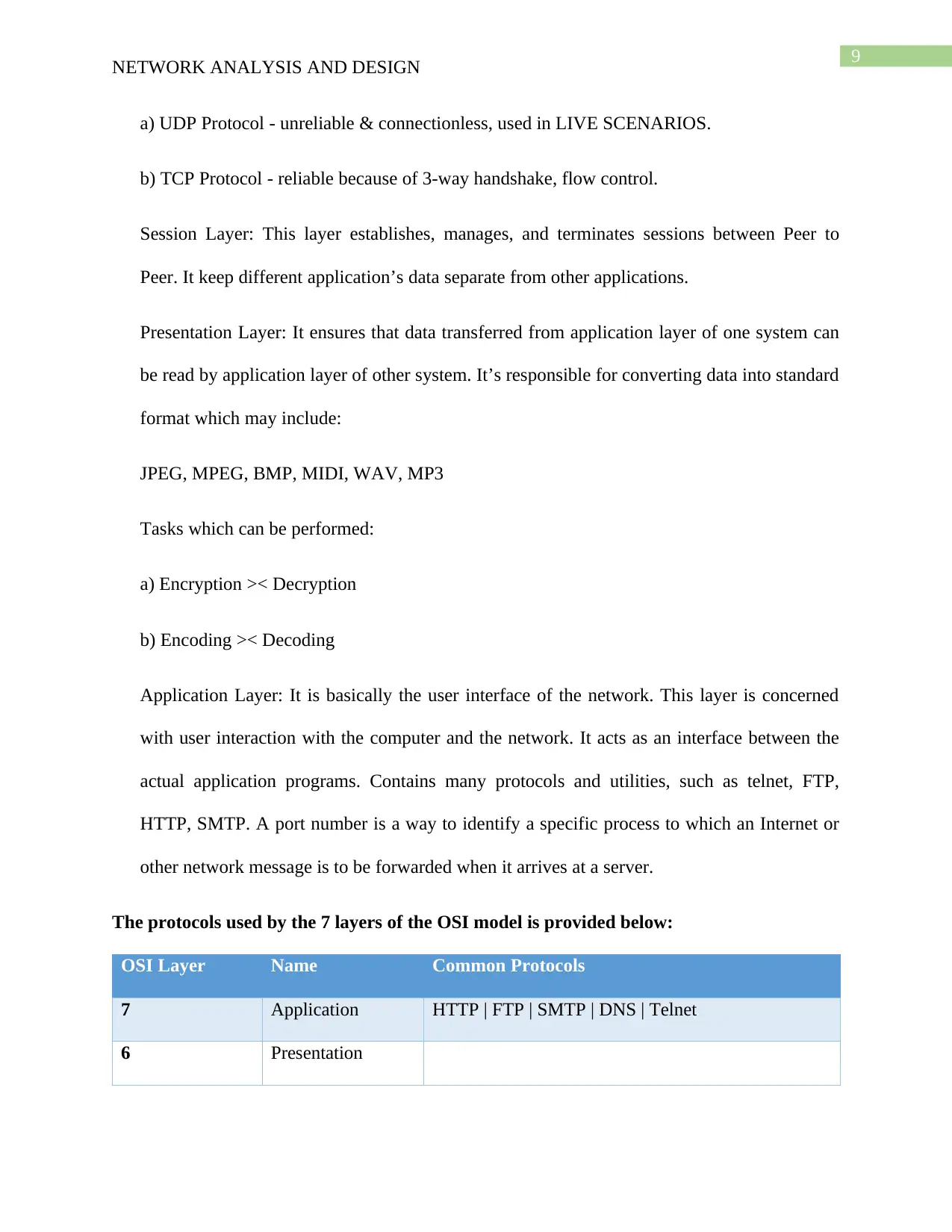
a) UDP Protocol - unreliable & connectionless, used in LIVE SCENARIOS.
b) TCP Protocol - reliable because of 3-way handshake, flow control.
Session Layer: This layer establishes, manages, and terminates sessions between Peer to
Peer. It keep different application’s data separate from other applications.
Presentation Layer: It ensures that data transferred from application layer of one system can
be read by application layer of other system. It’s responsible for converting data into standard
format which may include:
JPEG, MPEG, BMP, MIDI, WAV, MP3
Tasks which can be performed:
a) Encryption >< Decryption
b) Encoding >< Decoding
Application Layer: It is basically the user interface of the network. This layer is concerned
with user interaction with the computer and the network. It acts as an interface between the
actual application programs. Contains many protocols and utilities, such as telnet, FTP,
HTTP, SMTP. A port number is a way to identify a specific process to which an Internet or
other network message is to be forwarded when it arrives at a server.
The protocols used by the 7 layers of the OSI model is provided below:
OSI Layer Name Common Protocols
7 Application HTTP | FTP | SMTP | DNS | Telnet
6 Presentation
NETWORK ANALYSIS AND DESIGN
a) UDP Protocol - unreliable & connectionless, used in LIVE SCENARIOS.
b) TCP Protocol - reliable because of 3-way handshake, flow control.
Session Layer: This layer establishes, manages, and terminates sessions between Peer to
Peer. It keep different application’s data separate from other applications.
Presentation Layer: It ensures that data transferred from application layer of one system can
be read by application layer of other system. It’s responsible for converting data into standard
format which may include:
JPEG, MPEG, BMP, MIDI, WAV, MP3
Tasks which can be performed:
a) Encryption >< Decryption
b) Encoding >< Decoding
Application Layer: It is basically the user interface of the network. This layer is concerned
with user interaction with the computer and the network. It acts as an interface between the
actual application programs. Contains many protocols and utilities, such as telnet, FTP,
HTTP, SMTP. A port number is a way to identify a specific process to which an Internet or
other network message is to be forwarded when it arrives at a server.
The protocols used by the 7 layers of the OSI model is provided below:
OSI Layer Name Common Protocols
7 Application HTTP | FTP | SMTP | DNS | Telnet
6 Presentation
Paraphrase This Document
Need a fresh take? Get an instant paraphrase of this document with our AI Paraphraser
10
NETWORK ANALYSIS AND DESIGN
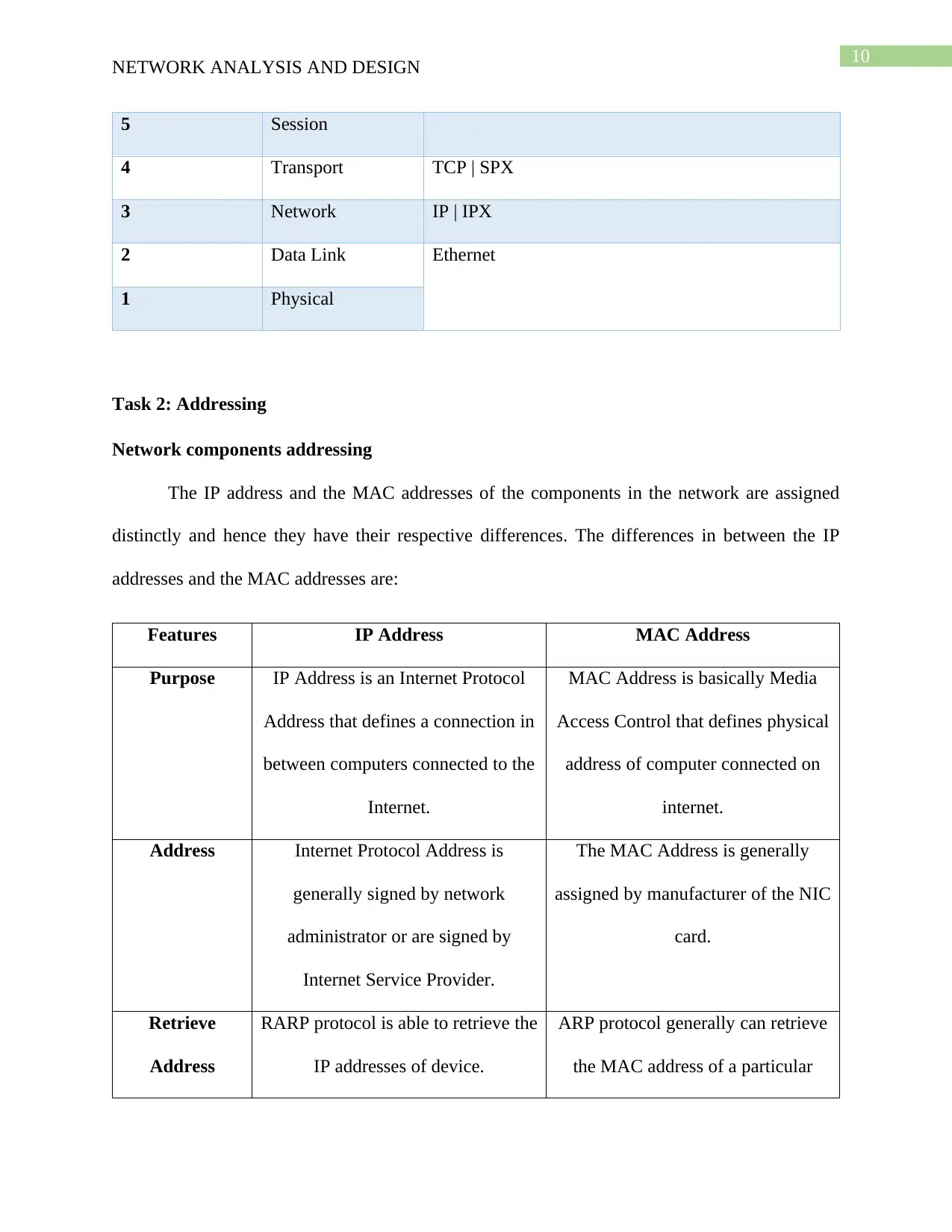
5 Session
4 Transport TCP | SPX
3 Network IP | IPX
2 Data Link Ethernet
1 Physical
Task 2: Addressing
Network components addressing
The IP address and the MAC addresses of the components in the network are assigned
distinctly and hence they have their respective differences. The differences in between the IP
addresses and the MAC addresses are:
Features IP Address MAC Address
Purpose IP Address is an Internet Protocol
Address that defines a connection in
between computers connected to the
Internet.
MAC Address is basically Media
Access Control that defines physical
address of computer connected on
internet.
Address Internet Protocol Address is
generally signed by network
administrator or are signed by
Internet Service Provider.
The MAC Address is generally
assigned by manufacturer of the NIC
card.
Retrieve
Address
RARP protocol is able to retrieve the
IP addresses of device.
ARP protocol generally can retrieve
the MAC address of a particular
NETWORK ANALYSIS AND DESIGN
5 Session
4 Transport TCP | SPX
3 Network IP | IPX
2 Data Link Ethernet
1 Physical
Task 2: Addressing
Network components addressing
The IP address and the MAC addresses of the components in the network are assigned
distinctly and hence they have their respective differences. The differences in between the IP
addresses and the MAC addresses are:
Features IP Address MAC Address
Purpose IP Address is an Internet Protocol
Address that defines a connection in
between computers connected to the
Internet.
MAC Address is basically Media
Access Control that defines physical
address of computer connected on
internet.
Address Internet Protocol Address is
generally signed by network
administrator or are signed by
Internet Service Provider.
The MAC Address is generally
assigned by manufacturer of the NIC
card.
Retrieve
Address
RARP protocol is able to retrieve the
IP addresses of device.
ARP protocol generally can retrieve
the MAC address of a particular
11
NETWORK ANALYSIS AND DESIGN
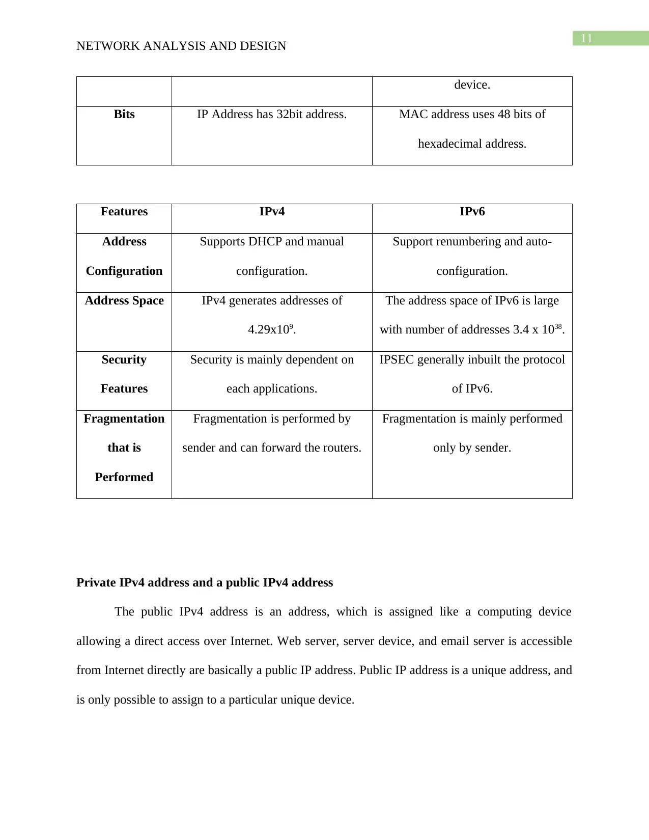
device.
Bits IP Address has 32bit address. MAC address uses 48 bits of
hexadecimal address.
Features IPv4 IPv6
Address
Configuration
Supports DHCP and manual
configuration.
Support renumbering and auto-
configuration.
Address Space IPv4 generates addresses of
4.29x10⁹.
The address space of IPv6 is large
with number of addresses 3.4 x 1038.
Security
Features
Security is mainly dependent on
each applications.
IPSEC generally inbuilt the protocol
of IPv6.
Fragmentation
that is
Performed
Fragmentation is performed by
sender and can forward the routers.
Fragmentation is mainly performed
only by sender.
Private IPv4 address and a public IPv4 address
The public IPv4 address is an address, which is assigned like a computing device
allowing a direct access over Internet. Web server, server device, and email server is accessible
from Internet directly are basically a public IP address. Public IP address is a unique address, and
is only possible to assign to a particular unique device.
NETWORK ANALYSIS AND DESIGN
device.
Bits IP Address has 32bit address. MAC address uses 48 bits of
hexadecimal address.
Features IPv4 IPv6
Address
Configuration
Supports DHCP and manual
configuration.
Support renumbering and auto-
configuration.
Address Space IPv4 generates addresses of
4.29x10⁹.
The address space of IPv6 is large
with number of addresses 3.4 x 1038.
Security
Features
Security is mainly dependent on
each applications.
IPSEC generally inbuilt the protocol
of IPv6.
Fragmentation
that is
Performed
Fragmentation is performed by
sender and can forward the routers.
Fragmentation is mainly performed
only by sender.
Private IPv4 address and a public IPv4 address
The public IPv4 address is an address, which is assigned like a computing device
allowing a direct access over Internet. Web server, server device, and email server is accessible
from Internet directly are basically a public IP address. Public IP address is a unique address, and
is only possible to assign to a particular unique device.
⊘ This is a preview!⊘
Do you want full access?
Subscribe today to unlock all pages.
Trusted by 1+ million students worldwide
1 out of 29
Related Documents


Your All-in-One AI-Powered Toolkit for Academic Success.
+13062052269
info@desklib.com
Available 24*7 on WhatsApp / Email
![[object Object]](/_next/static/media/star-bottom.7253800d.svg)
Unlock your academic potential
Copyright © 2020–2026 A2Z Services. All Rights Reserved. Developed and managed by ZUCOL.