Advanced Network Design and Implementation Report for IT College
VerifiedAdded on 2023/06/08
|12
|1921
|161
Report
AI Summary
This report details the design and implementation of a network for an IT college in Melbourne. It covers project scope, hardware requirements (including devices like computers, routers, switches, and servers), network security measures (firewalls and password encryption), and network diagrams for two buildings, including floor layouts. The report also includes network address tables and router configuration commands. The proposed network utilizes a star topology for efficiency, ensuring secure access and providing network connectivity for approximately 500 users. The design emphasizes the use of server rooms with proper ventilation and power management. The report includes references to support the design choices.
NETWORK IMPLEMENATION AND DESIGN
Registration Number:
Name:
Course:
Subjects
Date of Submission:
Registration Number:
Name:
Course:
Subjects
Date of Submission:
Paraphrase This Document
Need a fresh take? Get an instant paraphrase of this document with our AI Paraphraser
Table of Contents
Introduction......................................................................................................................................3
Project scope....................................................................................................................................3
Project hardware requirements........................................................................................................3
Server room..................................................................................................................................6
Network security..........................................................................................................................6
Network diagram.............................................................................................................................6
Building 1.................................................................................................................................6
Building 2.....................................................................................................................................7
Floor design..................................................................................................................................8
Commands used in Configurations................................................................................................10
Network address table............................................................................................................10
Router command......................................................................................................................10
Conclusion.....................................................................................................................................11
Introduction
This documentation is a proposal for design and implementation of a network in an IT college
that is located in Melbourne city. The investigation includes designing network diagrams for
each of the buildings that are within the college environment, both physical and legitimate
layouts [1]. The configuration additionally portrays hardware equipment required, topology
alternatives of the network, volume evaluated, asset prerequisites and the cost of establishment.
Project scope
The work to be performed during this process will involve design and installation of a suitable
network topology that will meet the requirements of the IT College. This will include
establishment and setup of all system gadgets, wiring and design of the floor layouts and fixing
the network components in their required positions. Fixing of the devices will involve switches,
routers, servers and configuring of computers to be compatible with the network system. Lastly
users will be taught on how to connect to the network.
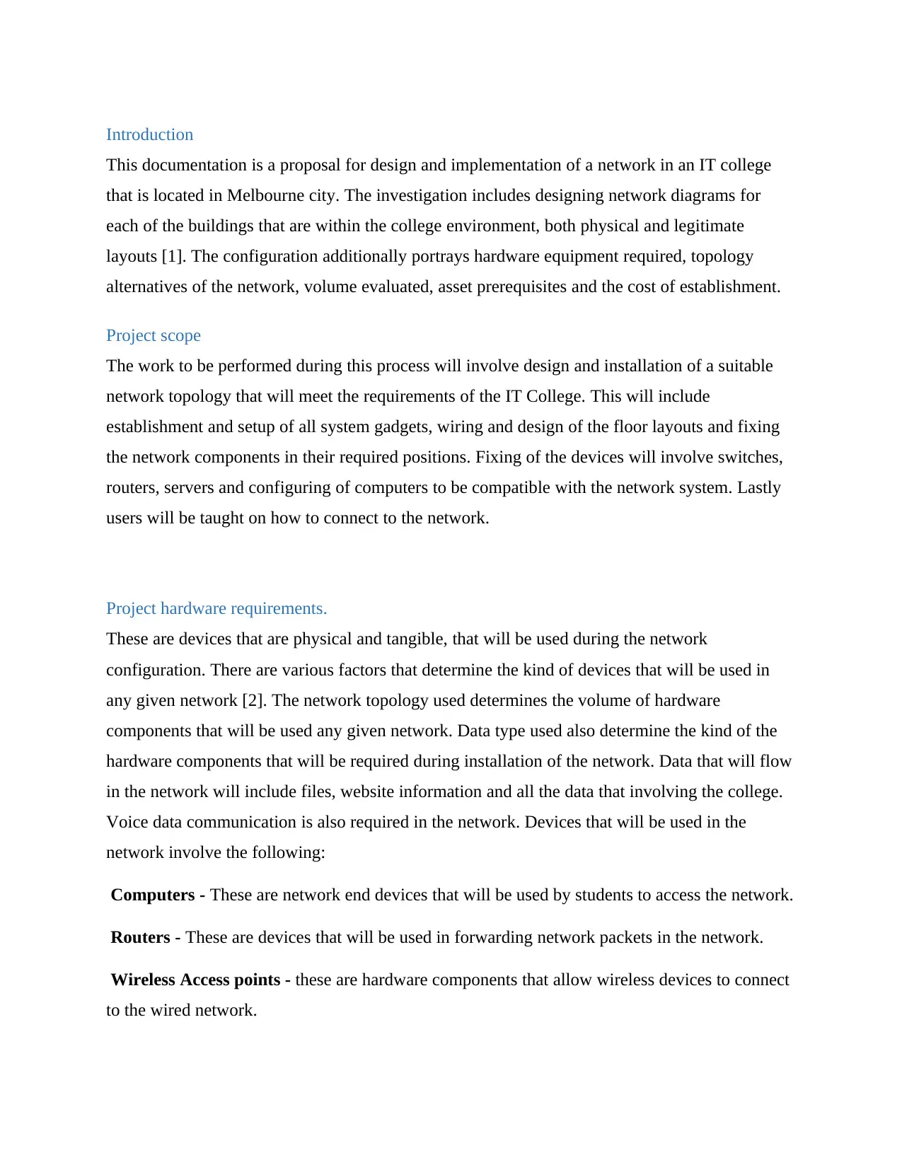
Project hardware requirements.
These are devices that are physical and tangible, that will be used during the network
configuration. There are various factors that determine the kind of devices that will be used in
any given network [2]. The network topology used determines the volume of hardware
components that will be used any given network. Data type used also determine the kind of the
hardware components that will be required during installation of the network. Data that will flow
in the network will include files, website information and all the data that involving the college.
Voice data communication is also required in the network. Devices that will be used in the
network involve the following:
Computers - These are network end devices that will be used by students to access the network.
Routers - These are devices that will be used in forwarding network packets in the network.
Wireless Access points - these are hardware components that allow wireless devices to connect
to the wired network.
This documentation is a proposal for design and implementation of a network in an IT college
that is located in Melbourne city. The investigation includes designing network diagrams for
each of the buildings that are within the college environment, both physical and legitimate
layouts [1]. The configuration additionally portrays hardware equipment required, topology
alternatives of the network, volume evaluated, asset prerequisites and the cost of establishment.
Project scope
The work to be performed during this process will involve design and installation of a suitable
network topology that will meet the requirements of the IT College. This will include
establishment and setup of all system gadgets, wiring and design of the floor layouts and fixing
the network components in their required positions. Fixing of the devices will involve switches,
routers, servers and configuring of computers to be compatible with the network system. Lastly
users will be taught on how to connect to the network.
Project hardware requirements.
These are devices that are physical and tangible, that will be used during the network
configuration. There are various factors that determine the kind of devices that will be used in
any given network [2]. The network topology used determines the volume of hardware
components that will be used any given network. Data type used also determine the kind of the
hardware components that will be required during installation of the network. Data that will flow
in the network will include files, website information and all the data that involving the college.
Voice data communication is also required in the network. Devices that will be used in the
network involve the following:
Computers - These are network end devices that will be used by students to access the network.
Routers - These are devices that will be used in forwarding network packets in the network.
Wireless Access points - these are hardware components that allow wireless devices to connect
to the wired network.
⊘ This is a preview!⊘
Do you want full access?
Subscribe today to unlock all pages.
Trusted by 1+ million students worldwide
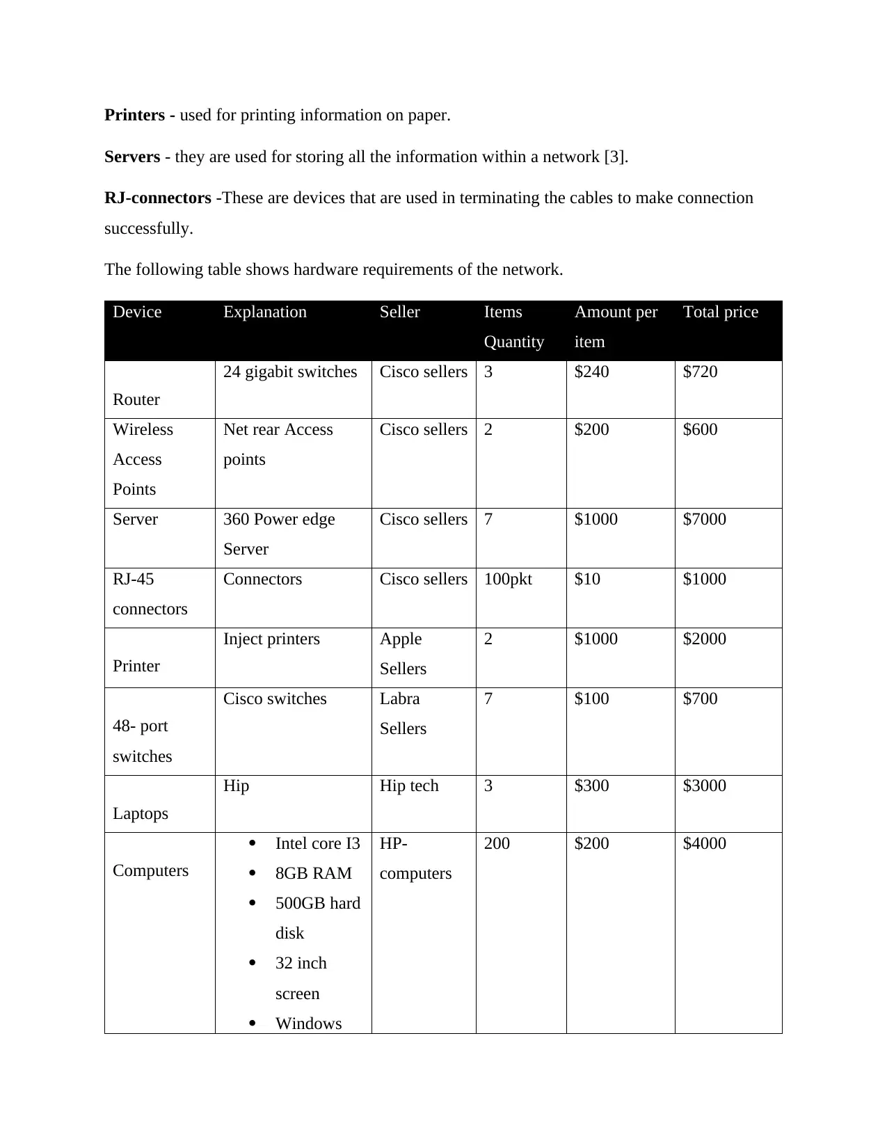
Printers - used for printing information on paper.
Servers - they are used for storing all the information within a network [3].
RJ-connectors -These are devices that are used in terminating the cables to make connection
successfully.
The following table shows hardware requirements of the network.
Device Explanation Seller Items
Quantity
Amount per
item
Total price
Router
24 gigabit switches Cisco sellers 3 $240 $720
Wireless
Access
Points
Net rear Access
points
Cisco sellers 2 $200 $600
Server 360 Power edge
Server
Cisco sellers 7 $1000 $7000
RJ-45
connectors
Connectors Cisco sellers 100pkt $10 $1000
Printer
Inject printers Apple
Sellers
2 $1000 $2000
48- port
switches
Cisco switches Labra
Sellers
7 $100 $700
Laptops
Hip Hip tech 3 $300 $3000
Computers
Intel core I3
8GB RAM
500GB hard
disk
32 inch
screen
Windows
HP-
computers
200 $200 $4000
Paraphrase This Document
Need a fresh take? Get an instant paraphrase of this document with our AI Paraphraser
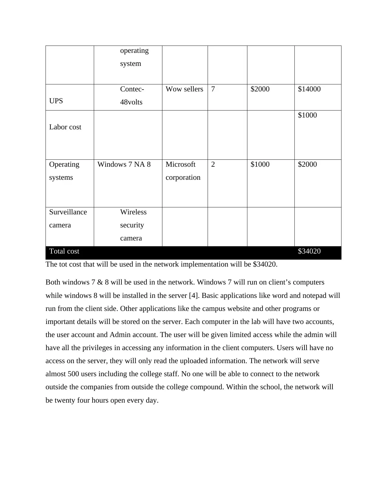
operating
system
UPS
Contec-
48volts
Wow sellers 7 $2000 $14000
Labor cost
$1000
Operating
systems
Windows 7 NA 8 Microsoft
corporation
2 $1000 $2000
Surveillance
camera
Wireless
security
camera
Total cost $34020
The tot cost that will be used in the network implementation will be $34020.
Both windows 7 & 8 will be used in the network. Windows 7 will run on client’s computers
while windows 8 will be installed in the server [4]. Basic applications like word and notepad will
run from the client side. Other applications like the campus website and other programs or
important details will be stored on the server. Each computer in the lab will have two accounts,
the user account and Admin account. The user will be given limited access while the admin will
have all the privileges in accessing any information in the client computers. Users will have no
access on the server, they will only read the uploaded information. The network will serve
almost 500 users including the college staff. No one will be able to connect to the network
outside the companies from outside the college compound. Within the school, the network will
be twenty four hours open every day.
Server room
The server will be located in each computer room .This means that each computer room will
have the server room. The server rooms will be well equipped and well ventilated with air
conditioners. Switches, servers and other electric components will be stored in this kind of
rooms. Cable trees will be used in cable management to make the room neat. Other devices like
Ups are used to control power in the server room to prevent damages to the available equipment
Network security
Several network firewalls will be installed in the system for security purposes. This will prevent
the network from security threats like malicious codes and Trojan viruses that may affect the
functioning of the network [5]. There will also be security to wireless networks so that only
students can connect to the network. The passwords will also be encrypted using AES algorithm
to prevent the attackers from cracking the passwords and having access to the network.
Network diagram
The following shows how different network devices will be arranged in the network
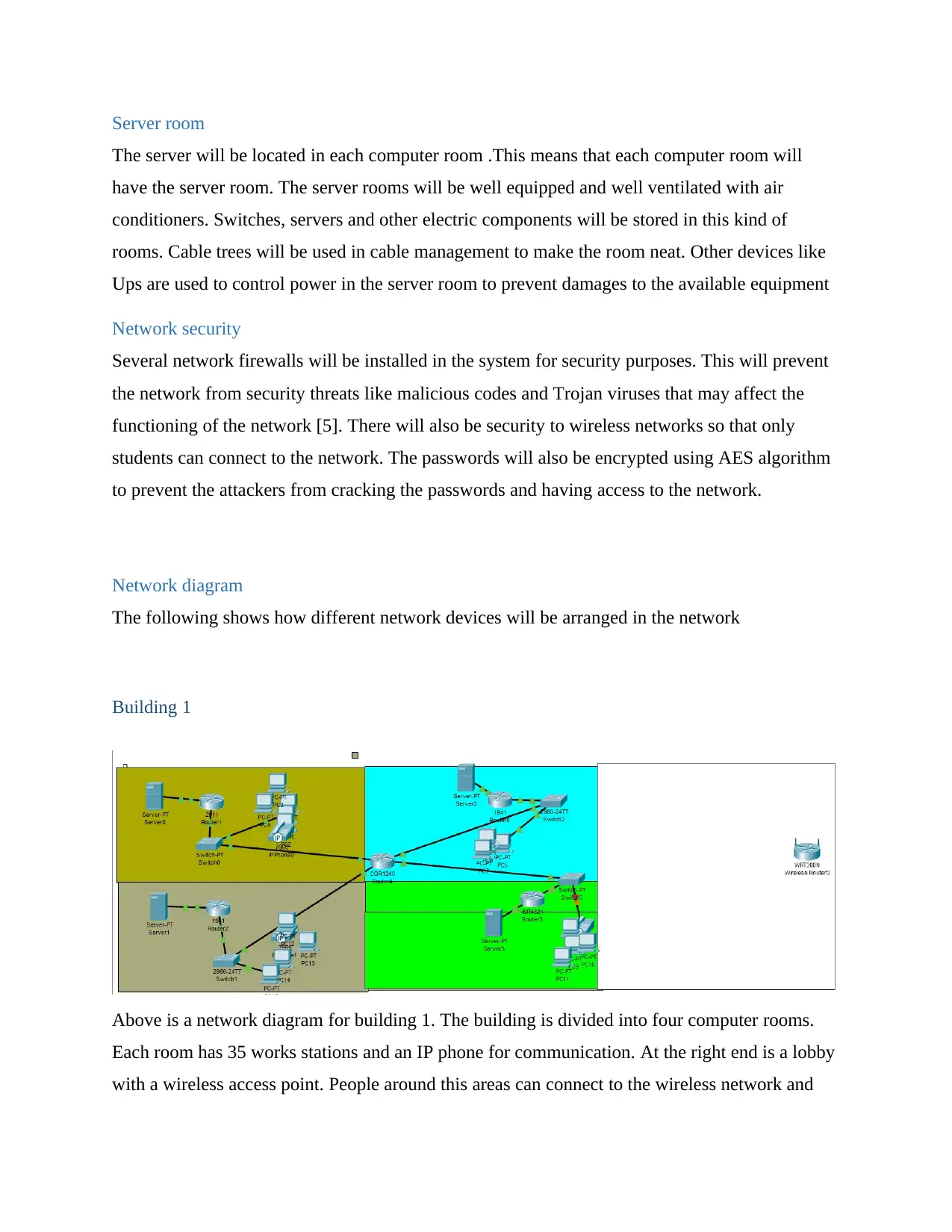
Building 1
Above is a network diagram for building 1. The building is divided into four computer rooms.
Each room has 35 works stations and an IP phone for communication. At the right end is a lobby
with a wireless access point. People around this areas can connect to the wireless network and
The server will be located in each computer room .This means that each computer room will
have the server room. The server rooms will be well equipped and well ventilated with air
conditioners. Switches, servers and other electric components will be stored in this kind of
rooms. Cable trees will be used in cable management to make the room neat. Other devices like
Ups are used to control power in the server room to prevent damages to the available equipment
Network security
Several network firewalls will be installed in the system for security purposes. This will prevent
the network from security threats like malicious codes and Trojan viruses that may affect the
functioning of the network [5]. There will also be security to wireless networks so that only
students can connect to the network. The passwords will also be encrypted using AES algorithm
to prevent the attackers from cracking the passwords and having access to the network.
Network diagram
The following shows how different network devices will be arranged in the network
Building 1
Above is a network diagram for building 1. The building is divided into four computer rooms.
Each room has 35 works stations and an IP phone for communication. At the right end is a lobby
with a wireless access point. People around this areas can connect to the wireless network and
⊘ This is a preview!⊘
Do you want full access?
Subscribe today to unlock all pages.
Trusted by 1+ million students worldwide
use it. The network in each room is connected to ISP so that the network in the building is
controlled from on region [6]. Computers are connected to the network from the switch using
Ethernet cables to form star topology.
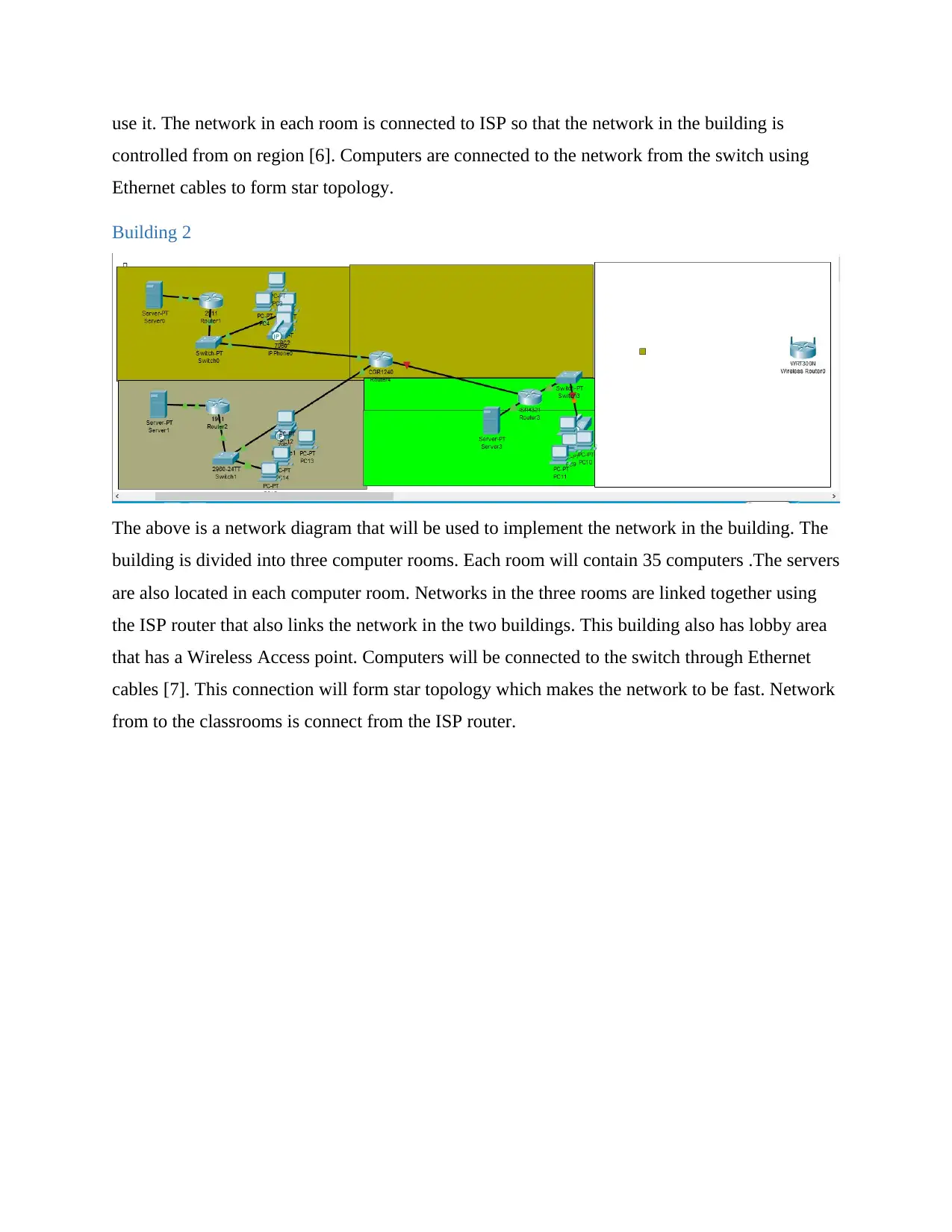
Building 2
The above is a network diagram that will be used to implement the network in the building. The
building is divided into three computer rooms. Each room will contain 35 computers .The servers
are also located in each computer room. Networks in the three rooms are linked together using
the ISP router that also links the network in the two buildings. This building also has lobby area
that has a Wireless Access point. Computers will be connected to the switch through Ethernet
cables [7]. This connection will form star topology which makes the network to be fast. Network
from to the classrooms is connect from the ISP router.
controlled from on region [6]. Computers are connected to the network from the switch using
Ethernet cables to form star topology.
Building 2
The above is a network diagram that will be used to implement the network in the building. The
building is divided into three computer rooms. Each room will contain 35 computers .The servers
are also located in each computer room. Networks in the three rooms are linked together using
the ISP router that also links the network in the two buildings. This building also has lobby area
that has a Wireless Access point. Computers will be connected to the switch through Ethernet
cables [7]. This connection will form star topology which makes the network to be fast. Network
from to the classrooms is connect from the ISP router.
Paraphrase This Document
Need a fresh take? Get an instant paraphrase of this document with our AI Paraphraser
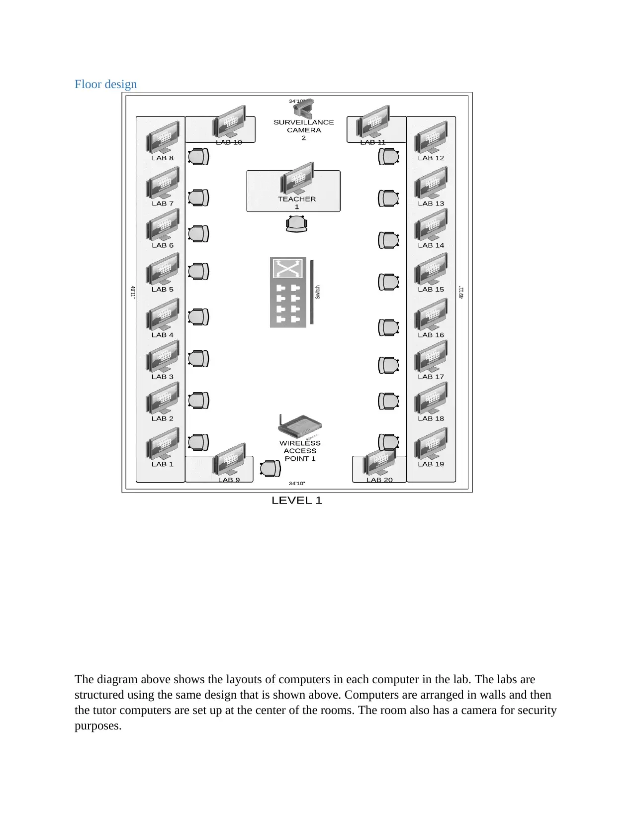
Floor design
The diagram above shows the layouts of computers in each computer in the lab. The labs are
structured using the same design that is shown above. Computers are arranged in walls and then
the tutor computers are set up at the center of the rooms. The room also has a camera for security
purposes.
The diagram above shows the layouts of computers in each computer in the lab. The labs are
structured using the same design that is shown above. Computers are arranged in walls and then
the tutor computers are set up at the center of the rooms. The room also has a camera for security
purposes.
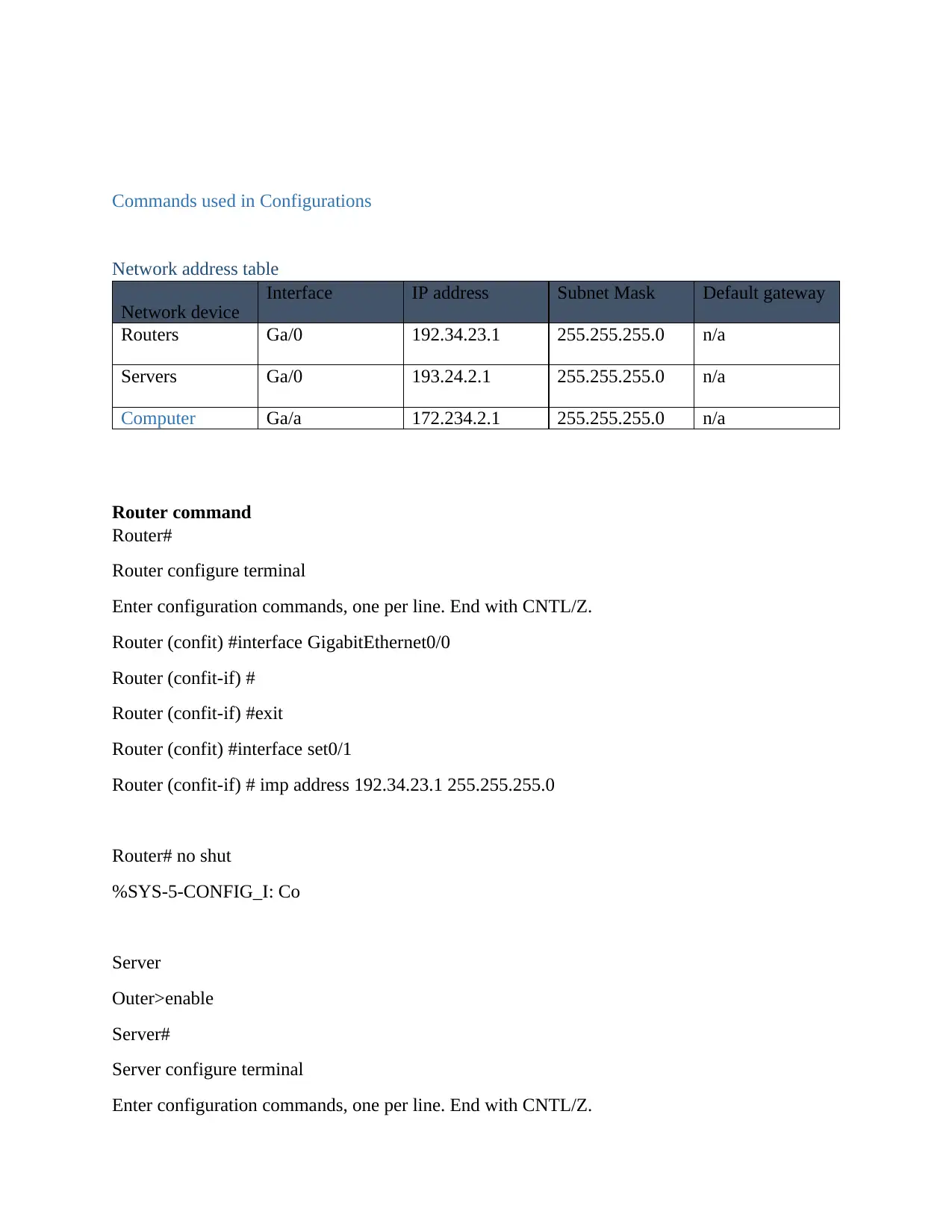
Commands used in Configurations
Network address table
Network device
Interface IP address Subnet Mask Default gateway
Routers Ga/0 192.34.23.1 255.255.255.0 n/a
Servers Ga/0 193.24.2.1 255.255.255.0 n/a
Computer Ga/a 172.234.2.1 255.255.255.0 n/a
Router command
Router#
Router configure terminal
Enter configuration commands, one per line. End with CNTL/Z.
Router (confit) #interface GigabitEthernet0/0
Router (confit-if) #
Router (confit-if) #exit
Router (confit) #interface set0/1
Router (confit-if) # imp address 192.34.23.1 255.255.255.0
Router# no shut
%SYS-5-CONFIG_I: Co
Server
Outer>enable
Server#
Server configure terminal
Enter configuration commands, one per line. End with CNTL/Z.
⊘ This is a preview!⊘
Do you want full access?
Subscribe today to unlock all pages.
Trusted by 1+ million students worldwide
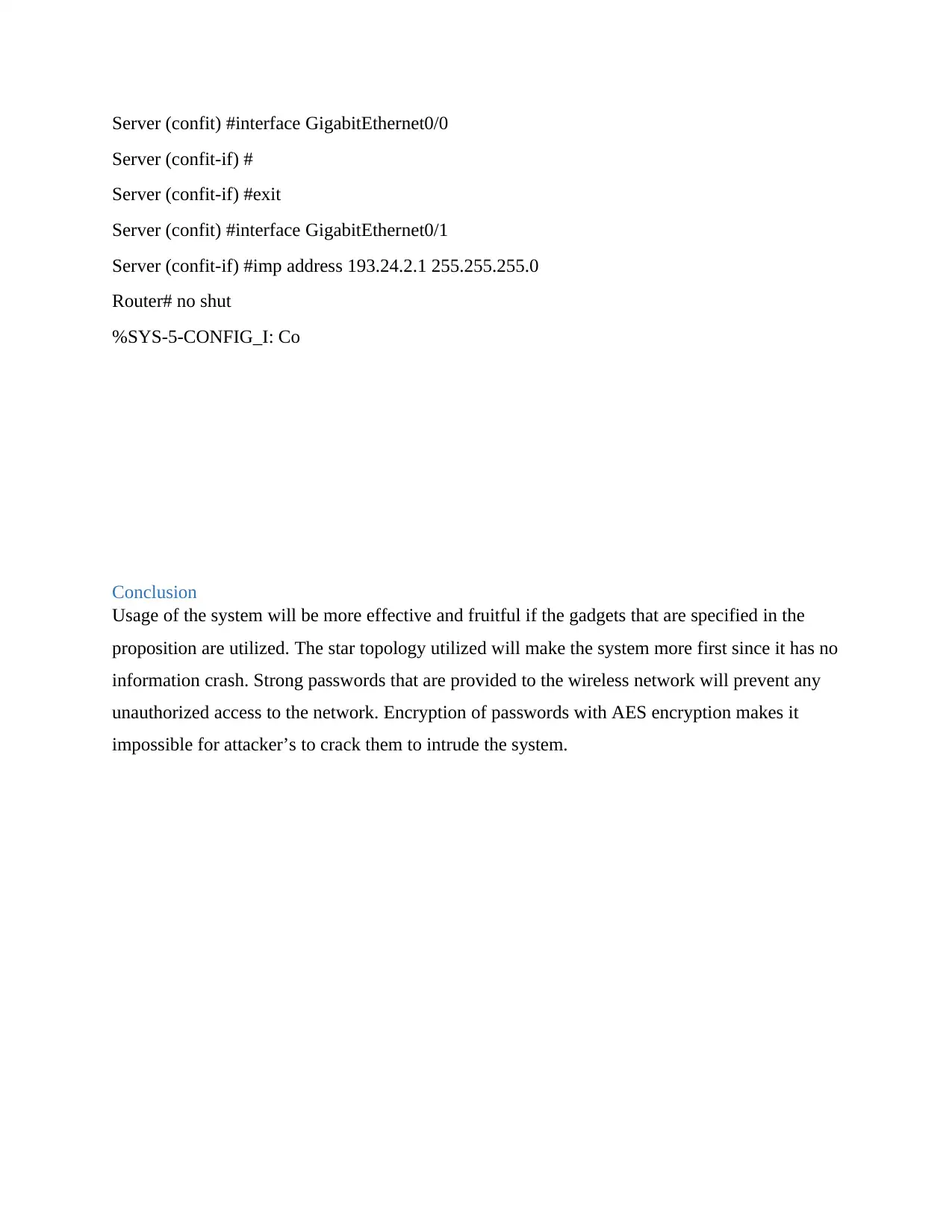
Server (confit) #interface GigabitEthernet0/0
Server (confit-if) #
Server (confit-if) #exit
Server (confit) #interface GigabitEthernet0/1
Server (confit-if) #imp address 193.24.2.1 255.255.255.0
Router# no shut
%SYS-5-CONFIG_I: Co
Conclusion
Usage of the system will be more effective and fruitful if the gadgets that are specified in the
proposition are utilized. The star topology utilized will make the system more first since it has no
information crash. Strong passwords that are provided to the wireless network will prevent any
unauthorized access to the network. Encryption of passwords with AES encryption makes it
impossible for attacker’s to crack them to intrude the system.
Paraphrase This Document
Need a fresh take? Get an instant paraphrase of this document with our AI Paraphraser
References
[1] Jiang, X., Dawson-Haggerty, S., Dutta, P. and Culler, D, Design and implementation of a
high-fidelity ac metering network. In Information Processing in Sensor Networks, 2009. IPSN
2009. International Conference on (pp. 253-264). IEEE, .2009
[2] Petra, R.K., Nedevschi, S., Surana, S., Sheth, A., Subramanian, L. and Brewer, E.A.,
WiLDNet: Design and Implementation of High Performance WiFi Based Long Distance
Networks. In NSDI (Vol. 1, No. 1, p. 1),2010.
[3] Pakzad, S.N., Fenves, G.L., Kim, S. and Culler, D.E. Design and implementation of scalable
wireless sensor network for structural monitoring. Journal of infrastructure systems, 14(1),
pp.89-101.2008
[4] Cabaret, J., Sommers, J., Braford, P., Stan, C., Tsing, D. and Wright, S. Power awareness in
network design and routing. In INFOCOM 2008. The 27th Conference on Computer
Communications. IEEE (pp. 457-465). IEEE, 2008.
[5] Han, D.M. and Lim, J.H. Design and implementation of smart home energy management
systems based on ZigBee. IEEE Transactions on Consumer Electronics, 56(3), 2010
[6] Milosz, E., Lane, N.D., Fodor, K., Peterson, R., Lu, H., Muscles, M., Eidelman, S.B., Zheng,
X. and Campbell, A.T. Sensing meets mobile social networks: the design, implementation and
evaluation of the concede application. In Proceedings of the 6th ACM conference on Embedded
network sensor systems (pp. 337-350). ACM, 2008.
[6] Kodak, C., Marks, J. and Stieber, S. Automating the layout of network diagrams with
specified visual organization. IEEE Transactions on Systems, Man, and Cybernetics, 24(3),
pp.440-454, 2008.
[7] Wang, S.Y., Chou, C.L. and Lin, C.C. The design and implementation of the Nuns network
simulation engine. Simulation Modelling Practice and Theory, 15(1), pp.57-81, 2011.

⊘ This is a preview!⊘
Do you want full access?
Subscribe today to unlock all pages.
Trusted by 1+ million students worldwide
1 out of 12
Related Documents


Your All-in-One AI-Powered Toolkit for Academic Success.
+13062052269
info@desklib.com
Available 24*7 on WhatsApp / Email
![[object Object]](/_next/static/media/star-bottom.7253800d.svg)
Unlock your academic potential
Copyright © 2020–2026 A2Z Services. All Rights Reserved. Developed and managed by ZUCOL.