Network Design: Implementing Routing and Access Restrictions Project
VerifiedAdded on  2022/10/11
|16
|1836
|7
Project
AI Summary
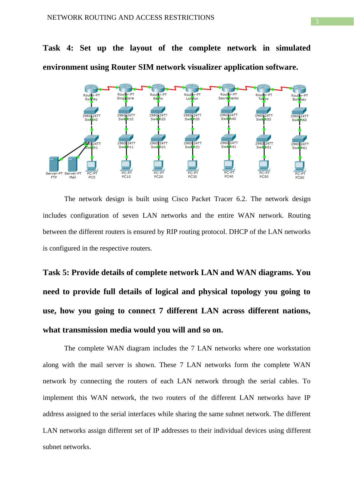
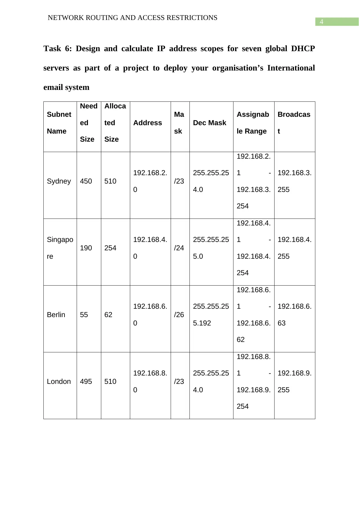
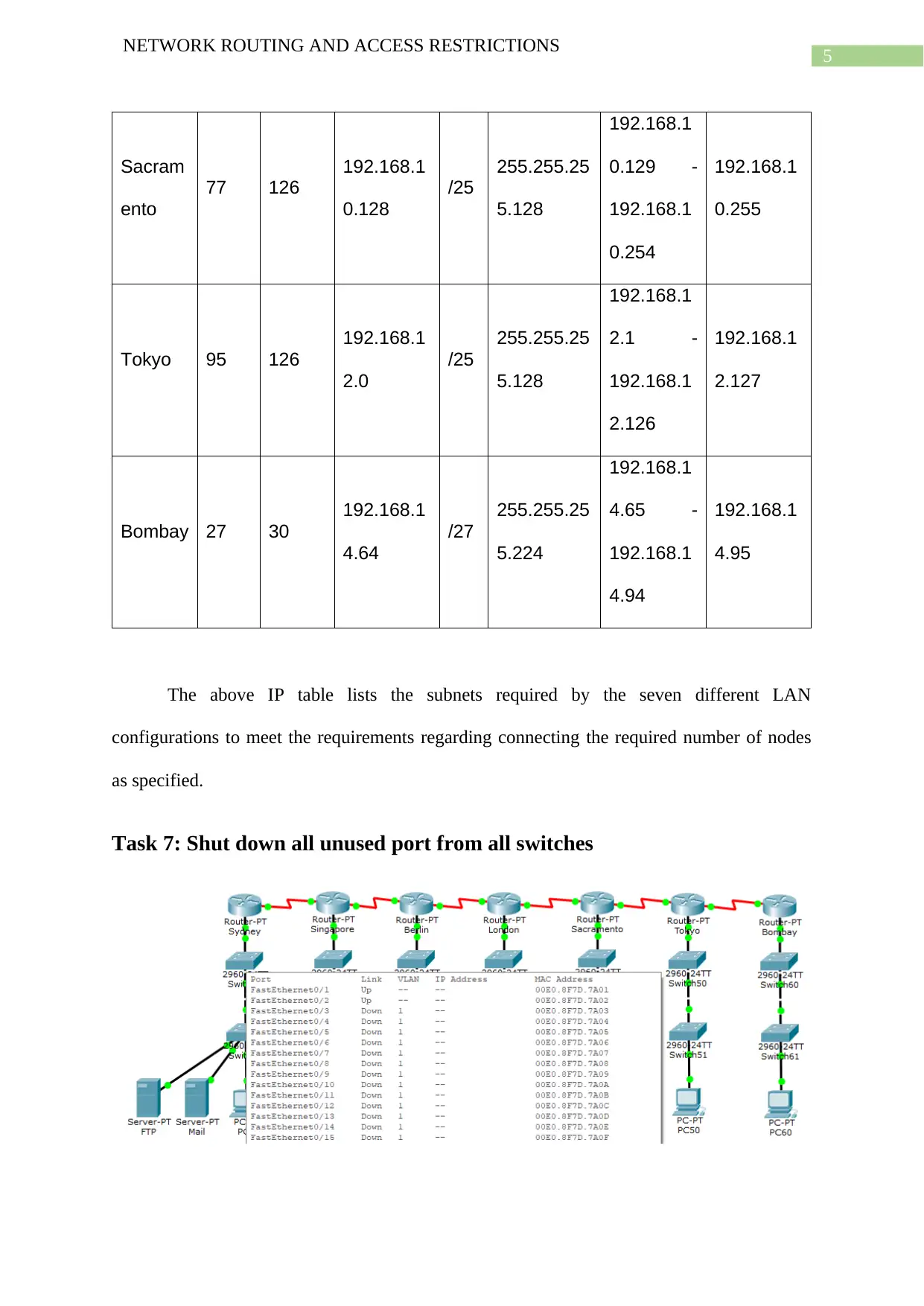
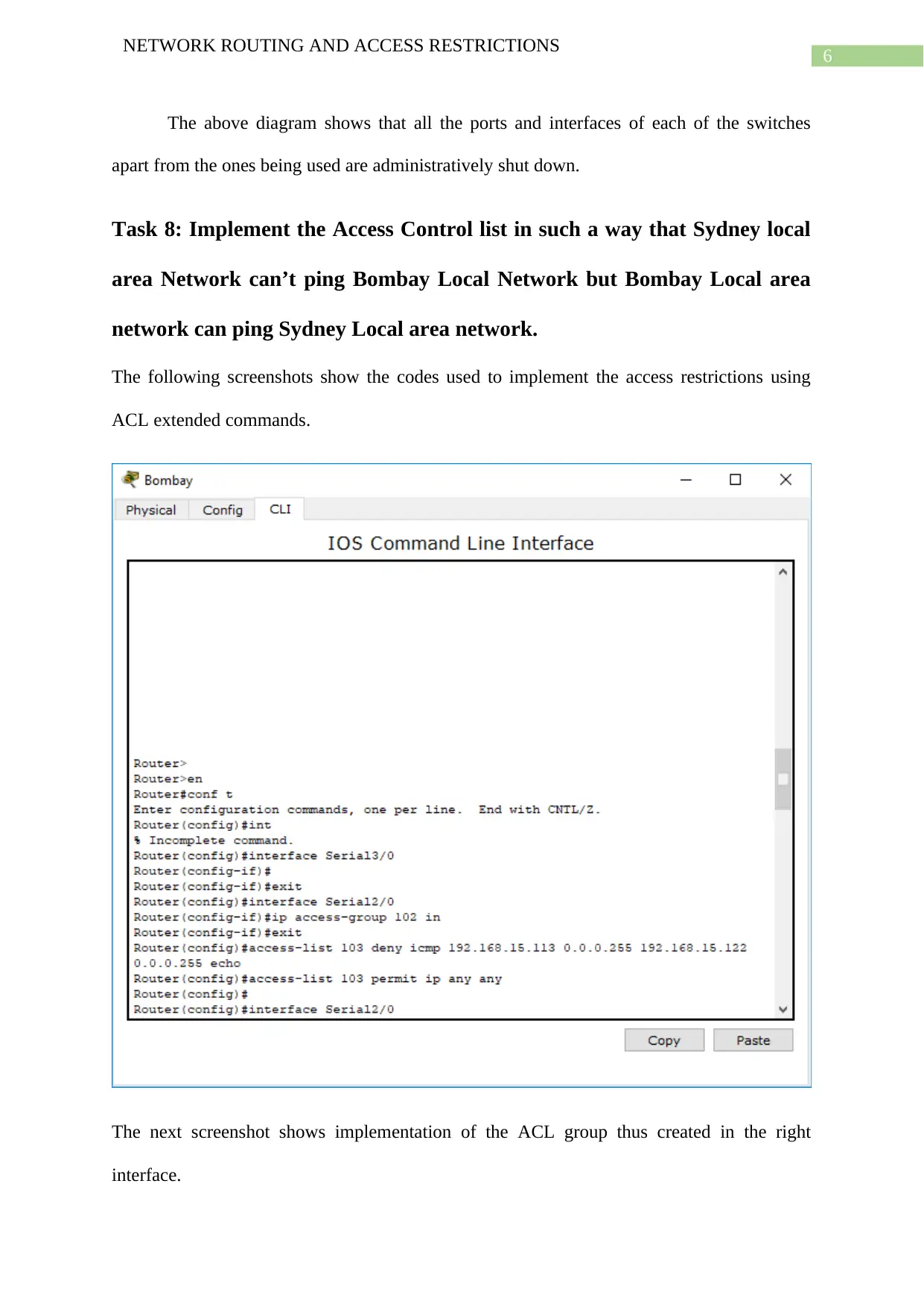
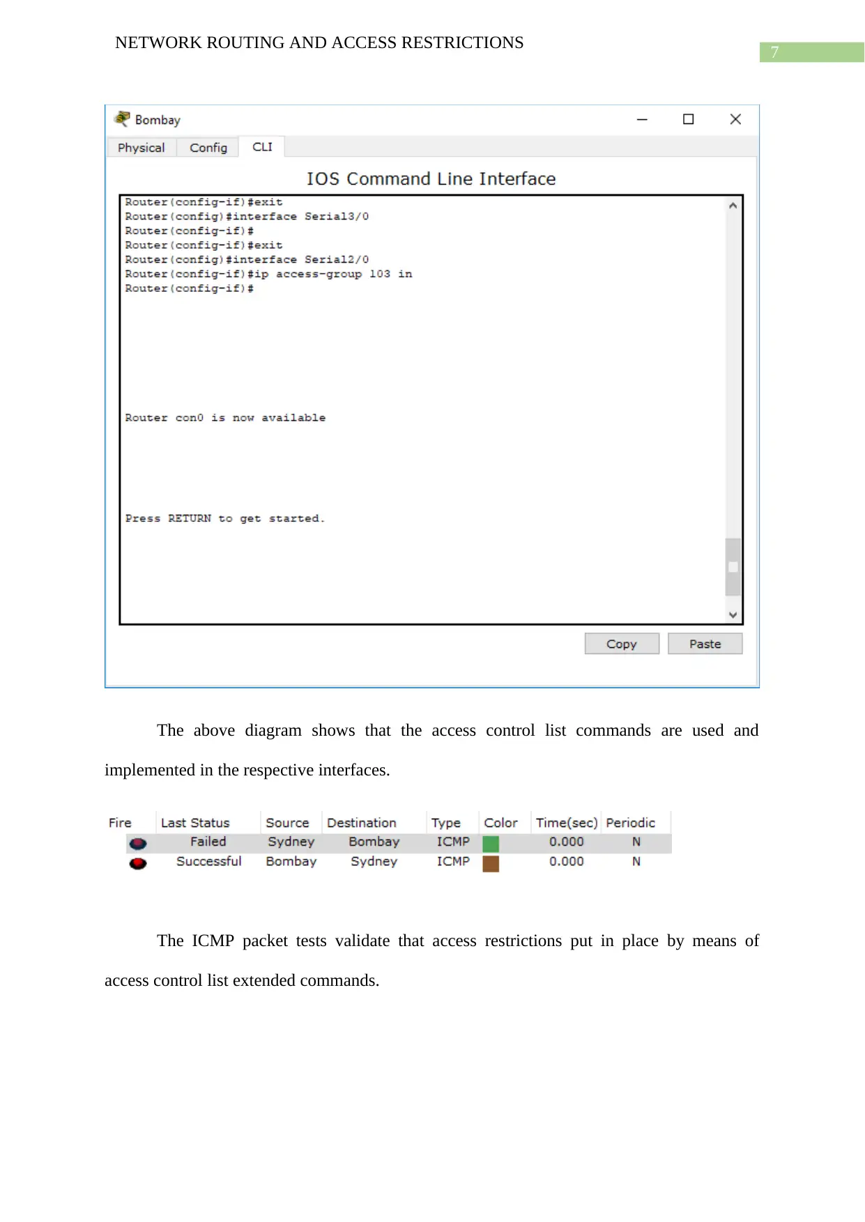
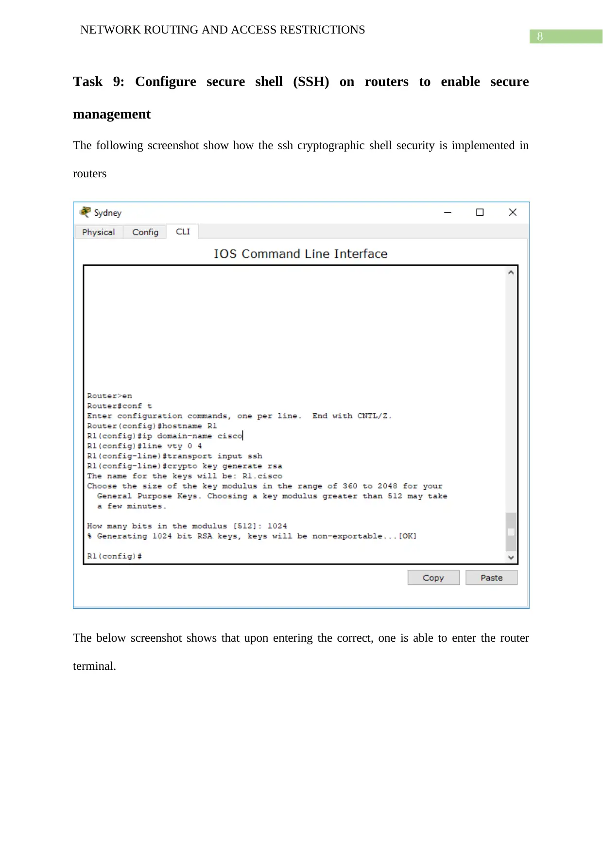
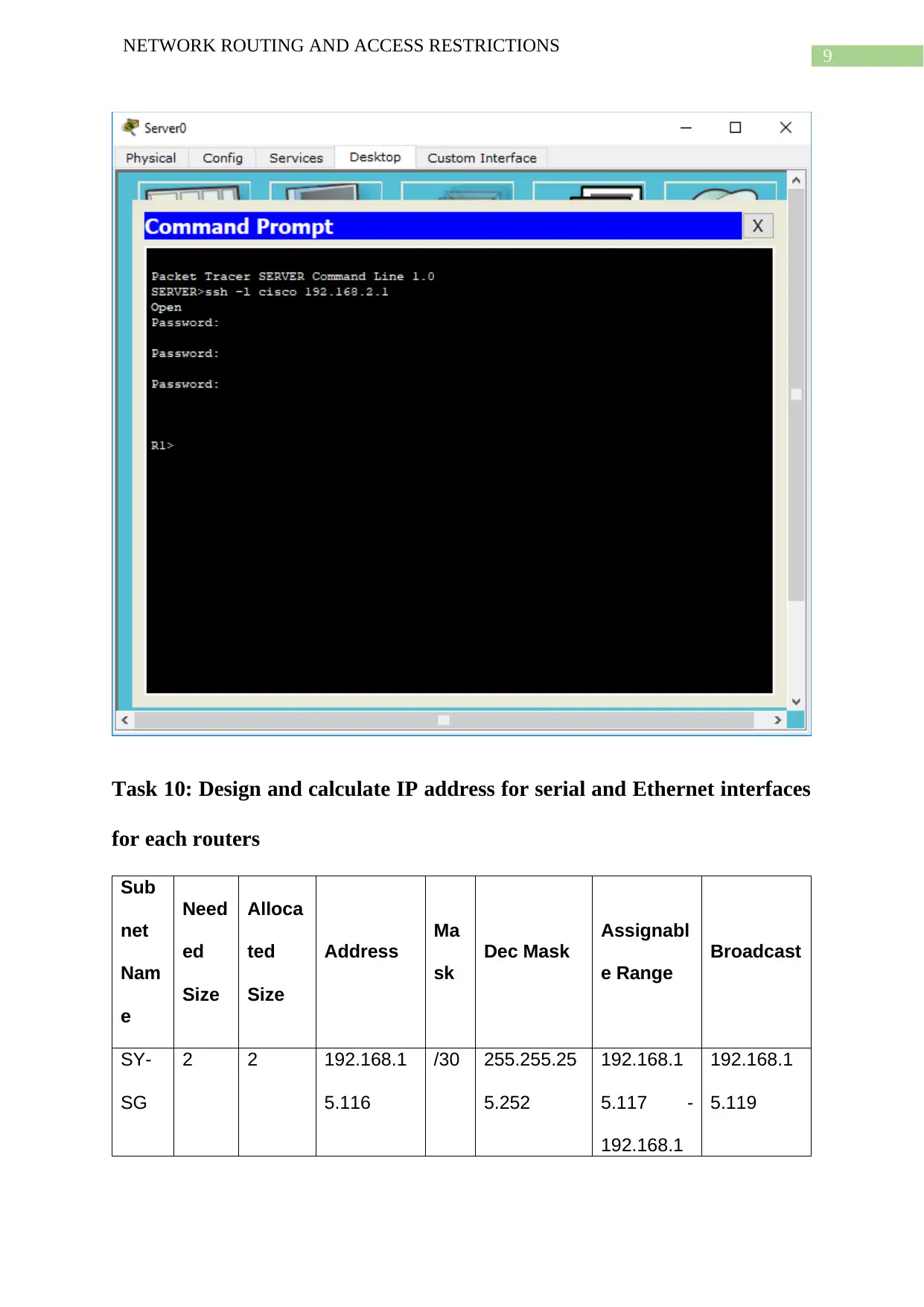
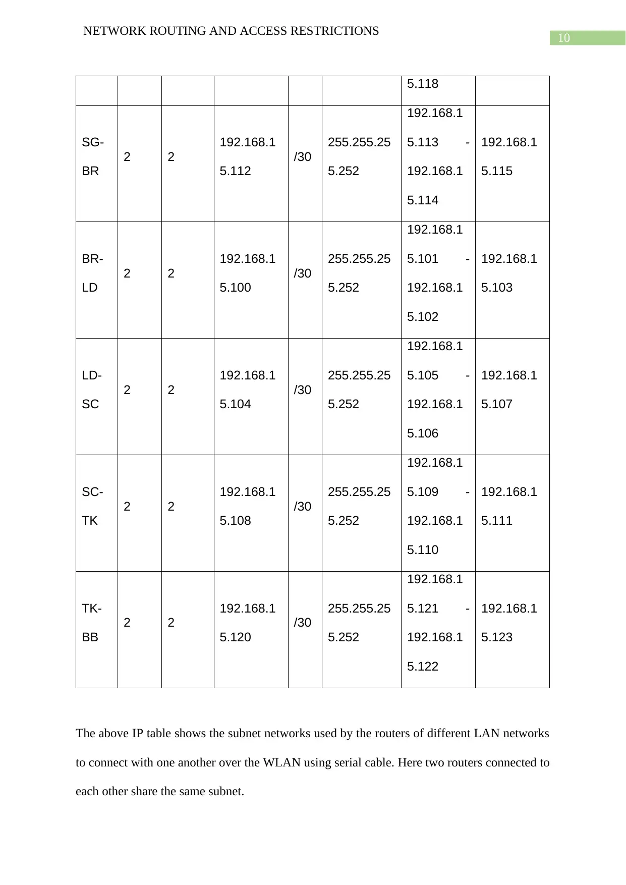
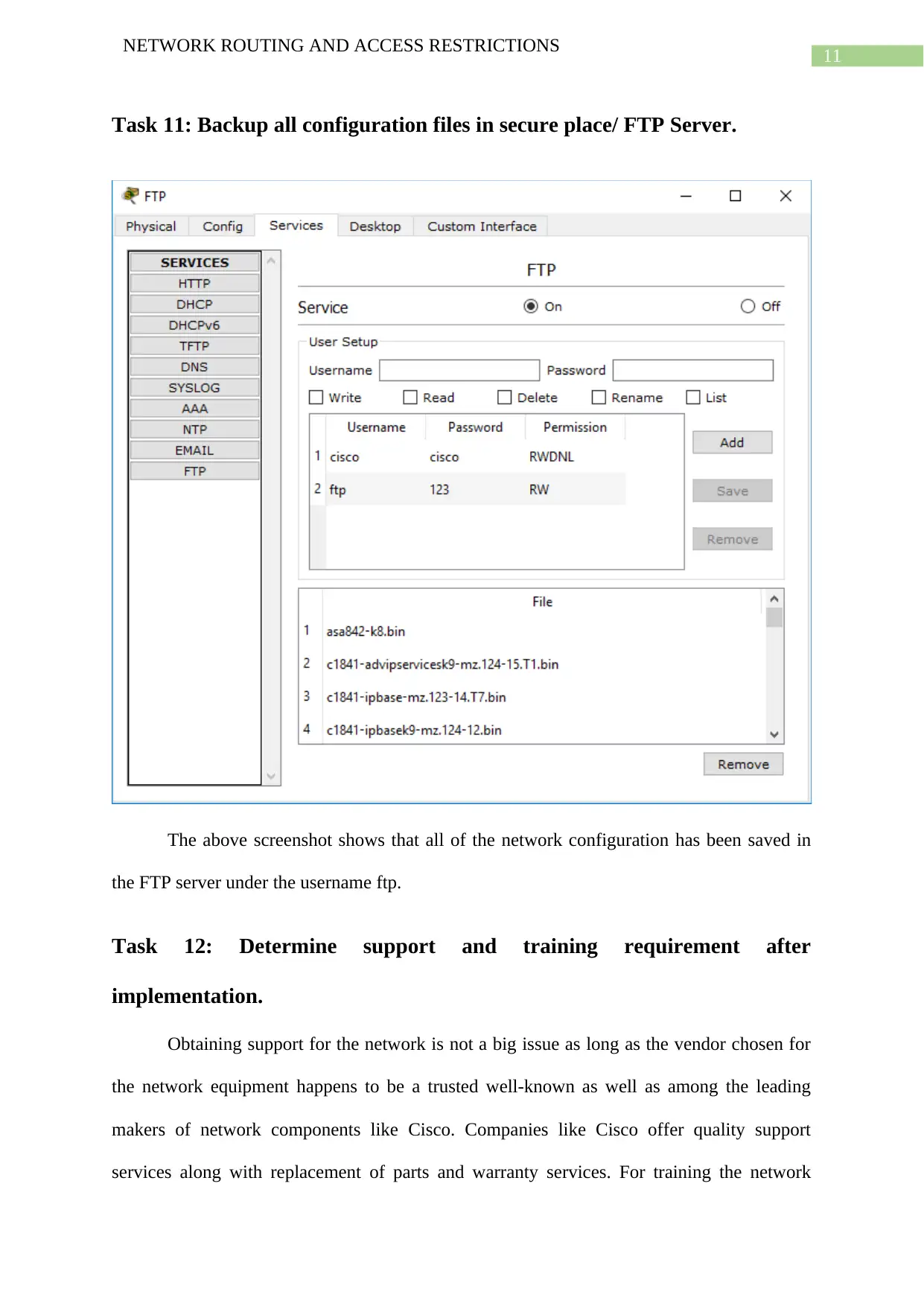
This project details the design and implementation of a complex Wide Area Network (WAN) comprising seven Local Area Networks (LANs) located across different cities. The student utilized Cisco Packet Tracer to simulate the network, incorporating various routers, switches, and network devices. Key aspects include the selection and configuration of routers and switches, including multilayer and layer 2 switches, along with the specification of appropriate cabling. The project covers IP address allocation, subnetting, and the configuration of DHCP servers for each LAN. A significant portion of the project focuses on access control, including the implementation of Access Control Lists (ACLs) to restrict network access between specific LANs. Furthermore, the project demonstrates the configuration of Secure Shell (SSH) for secure router management, the design of IP address scopes for network interfaces, and the backup of network configurations to an FTP server. The project also addresses vendor selection, technical specifications, and support requirements, including the use of Cisco network equipment. The project concludes with a bibliography of cited sources.

Running head: NETWORK ROUTING AND ACCESS RESTRICTIONS
Network Routing and Access Restrictions
Name of the Student
Name of the University
Author Note
Network Routing and Access Restrictions
Name of the Student
Name of the University
Author Note
Paraphrase This Document
Need a fresh take? Get an instant paraphrase of this document with our AI Paraphraser

1
NETWORK ROUTING AND ACCESS RESTRICTIONS
Task 1: What types of routers are needed and how many of them are
required according to given specification.
It is the generic routers available in Cisco Packet Tracer which are taken to setup the
LAN networks for each of the following cities – Sydney, Singapore, Berlin, London,
Sacramento, Tokyo and Bombay.
Task 2: How many switches are needed for this complete project and what
type of switches will be suitable for each LAN.
Only one multilayer switch is required for all the LAN networks. However, the access layer
switches will vary in number among every network.
Since the Sydney network requires 450 nodes, number of layer 2 switches required for this
network is 450/24 = 18.75 or 19 layer 2 switches.
Since the Singapore network requires 190 nodes, number of layer 2 switches required for this
network is 190/24 = 7.916 or 8 layer 2 switches.
Since the Berlin network requires 55 nodes, number of layer 2 switches required for this
network is 55/24 = 2.29 or 3 layer 2 switches.
Since the London network requires 495 nodes, number of layer 2 switches required for this
network is 495/24 = 20.625 or 21 layer 2 switches.
Since the Sacramento network requires 77 nodes, number of layer 2 switches required for this
network is 77/24 = 3.2 or 4 layer 2 switches.
Since the Singapore network requires 95 nodes, number of layer 2 switches required for this
network is 95/24 = 3.958 or 4 layer 2 switches.

2
NETWORK ROUTING AND ACCESS RESTRICTIONS
Since the Bombay network requires 27 nodes, number of layer 2 switches required for this
network is 2.
The network requires two kinds of switches for every LAN configuration i) a multilayer
switch and ii) layer 2 switch.
Task 3: Establish the sitting and types of terminals, processors and
required protocols and architecture based on technical specification and
requirements.
The cables used by the routers of every LAN configuration for connecting the
multilayer switch as also by layer 2 switches for connecting individual devices are straight
through cables. Cable used by the multilayer switch for connecting the layer 2 switches are
cross over cables. Cables used by routers of one LAN network to connect router of another
LAN network are serial cables.
The processors required for the workstations and servers involved in the network are
Intel core or AMD ryzen series of CPUs for the workstations and Intel xeon or AMD opteron
for the servers.
⊘ This is a preview!⊘
Do you want full access?
Subscribe today to unlock all pages.

Trusted by 1+ million students worldwide

3
NETWORK ROUTING AND ACCESS RESTRICTIONS
Task 4: Set up the layout of the complete network in simulated
environment using Router SIM network visualizer application software.
The network design is built using Cisco Packet Tracer 6.2. The network design
includes configuration of seven LAN networks and the entire WAN network. Routing
between the different routers is ensured by RIP routing protocol. DHCP of the LAN networks
is configured in the respective routers.
Task 5: Provide details of complete network LAN and WAN diagrams. You
need to provide full details of logical and physical topology you going to
use, how you going to connect 7 different LAN across different nations,
what transmission media would you will and so on.
The complete WAN diagram includes the 7 LAN networks where one workstation
along with the mail server is shown. These 7 LAN networks form the complete WAN
network by connecting the routers of each LAN network through the serial cables. To
implement this WAN network, the two routers of the different LAN networks have IP
address assigned to the serial interfaces while sharing the same subnet network. The different
LAN networks assign different set of IP addresses to their individual devices using different
subnet networks.
Paraphrase This Document
Need a fresh take? Get an instant paraphrase of this document with our AI Paraphraser

4
NETWORK ROUTING AND ACCESS RESTRICTIONS
Task 6: Design and calculate IP address scopes for seven global DHCP
servers as part of a project to deploy your organisation’s International
email system
Subnet
Name
Need
ed
Size
Alloca
ted
Size
Address
Ma
sk
Dec Mask
Assignab
le Range
Broadcas
t
Sydney 450 510
192.168.2.
0
/23
255.255.25
4.0
192.168.2.
1 -
192.168.3.
254
192.168.3.
255
Singapo
re
190 254
192.168.4.
0
/24
255.255.25
5.0
192.168.4.
1 -
192.168.4.
254
192.168.4.
255
Berlin 55 62
192.168.6.
0
/26
255.255.25
5.192
192.168.6.
1 -
192.168.6.
62
192.168.6.
63
London 495 510
192.168.8.
0
/23
255.255.25
4.0
192.168.8.
1 -
192.168.9.
254
192.168.9.
255

5
NETWORK ROUTING AND ACCESS RESTRICTIONS
Sacram
ento
77 126
192.168.1
0.128
/25
255.255.25
5.128
192.168.1
0.129 -
192.168.1
0.254
192.168.1
0.255
Tokyo 95 126
192.168.1
2.0
/25
255.255.25
5.128
192.168.1
2.1 -
192.168.1
2.126
192.168.1
2.127
Bombay 27 30
192.168.1
4.64
/27
255.255.25
5.224
192.168.1
4.65 -
192.168.1
4.94
192.168.1
4.95
The above IP table lists the subnets required by the seven different LAN
configurations to meet the requirements regarding connecting the required number of nodes
as specified.
Task 7: Shut down all unused port from all switches
⊘ This is a preview!⊘
Do you want full access?
Subscribe today to unlock all pages.

Trusted by 1+ million students worldwide

6
NETWORK ROUTING AND ACCESS RESTRICTIONS
The above diagram shows that all the ports and interfaces of each of the switches
apart from the ones being used are administratively shut down.
Task 8: Implement the Access Control list in such a way that Sydney local
area Network can’t ping Bombay Local Network but Bombay Local area
network can ping Sydney Local area network.
The following screenshots show the codes used to implement the access restrictions using
ACL extended commands.
The next screenshot shows implementation of the ACL group thus created in the right
interface.
Paraphrase This Document
Need a fresh take? Get an instant paraphrase of this document with our AI Paraphraser

7
NETWORK ROUTING AND ACCESS RESTRICTIONS
The above diagram shows that the access control list commands are used and
implemented in the respective interfaces.
The ICMP packet tests validate that access restrictions put in place by means of
access control list extended commands.
NETWORK ROUTING AND ACCESS RESTRICTIONS
The above diagram shows that the access control list commands are used and
implemented in the respective interfaces.
The ICMP packet tests validate that access restrictions put in place by means of
access control list extended commands.

8
NETWORK ROUTING AND ACCESS RESTRICTIONS
Task 9: Configure secure shell (SSH) on routers to enable secure
management
The following screenshot show how the ssh cryptographic shell security is implemented in
routers
The below screenshot shows that upon entering the correct, one is able to enter the router
terminal.
⊘ This is a preview!⊘
Do you want full access?
Subscribe today to unlock all pages.

Trusted by 1+ million students worldwide

9
NETWORK ROUTING AND ACCESS RESTRICTIONS
Task 10: Design and calculate IP address for serial and Ethernet interfaces
for each routers
Sub
net
Nam
e
Need
ed
Size
Alloca
ted
Size
Address
Ma
sk
Dec Mask
Assignabl
e Range
Broadcast
SY-
SG
2 2 192.168.1
5.116
/30 255.255.25
5.252
192.168.1
5.117 -
192.168.1
192.168.1
5.119
Paraphrase This Document
Need a fresh take? Get an instant paraphrase of this document with our AI Paraphraser

10
NETWORK ROUTING AND ACCESS RESTRICTIONS
5.118
SG-
BR
2 2
192.168.1
5.112
/30
255.255.25
5.252
192.168.1
5.113 -
192.168.1
5.114
192.168.1
5.115
BR-
LD
2 2
192.168.1
5.100
/30
255.255.25
5.252
192.168.1
5.101 -
192.168.1
5.102
192.168.1
5.103
LD-
SC
2 2
192.168.1
5.104
/30
255.255.25
5.252
192.168.1
5.105 -
192.168.1
5.106
192.168.1
5.107
SC-
TK
2 2
192.168.1
5.108
/30
255.255.25
5.252
192.168.1
5.109 -
192.168.1
5.110
192.168.1
5.111
TK-
BB
2 2
192.168.1
5.120
/30
255.255.25
5.252
192.168.1
5.121 -
192.168.1
5.122
192.168.1
5.123
The above IP table shows the subnet networks used by the routers of different LAN networks
to connect with one another over the WLAN using serial cable. Here two routers connected to
each other share the same subnet.

11
NETWORK ROUTING AND ACCESS RESTRICTIONS
Task 11: Backup all configuration files in secure place/ FTP Server.
The above screenshot shows that all of the network configuration has been saved in
the FTP server under the username ftp.
Task 12: Determine support and training requirement after
implementation.
Obtaining support for the network is not a big issue as long as the vendor chosen for
the network equipment happens to be a trusted well-known as well as among the leading
makers of network components like Cisco. Companies like Cisco offer quality support
services along with replacement of parts and warranty services. For training the network
⊘ This is a preview!⊘
Do you want full access?
Subscribe today to unlock all pages.

Trusted by 1+ million students worldwide
1 out of 16
Related Documents

Your All-in-One AI-Powered Toolkit for Academic Success.
 +13062052269
info@desklib.com
Available 24*7 on WhatsApp / Email
Unlock your academic potential
Copyright © 2020–2025 A2Z Services. All Rights Reserved. Developed and managed by ZUCOL.