Advanced Network Design Project: College IT Infrastructure Solution
VerifiedAdded on 2023/06/07
|11
|768
|275
Project
AI Summary
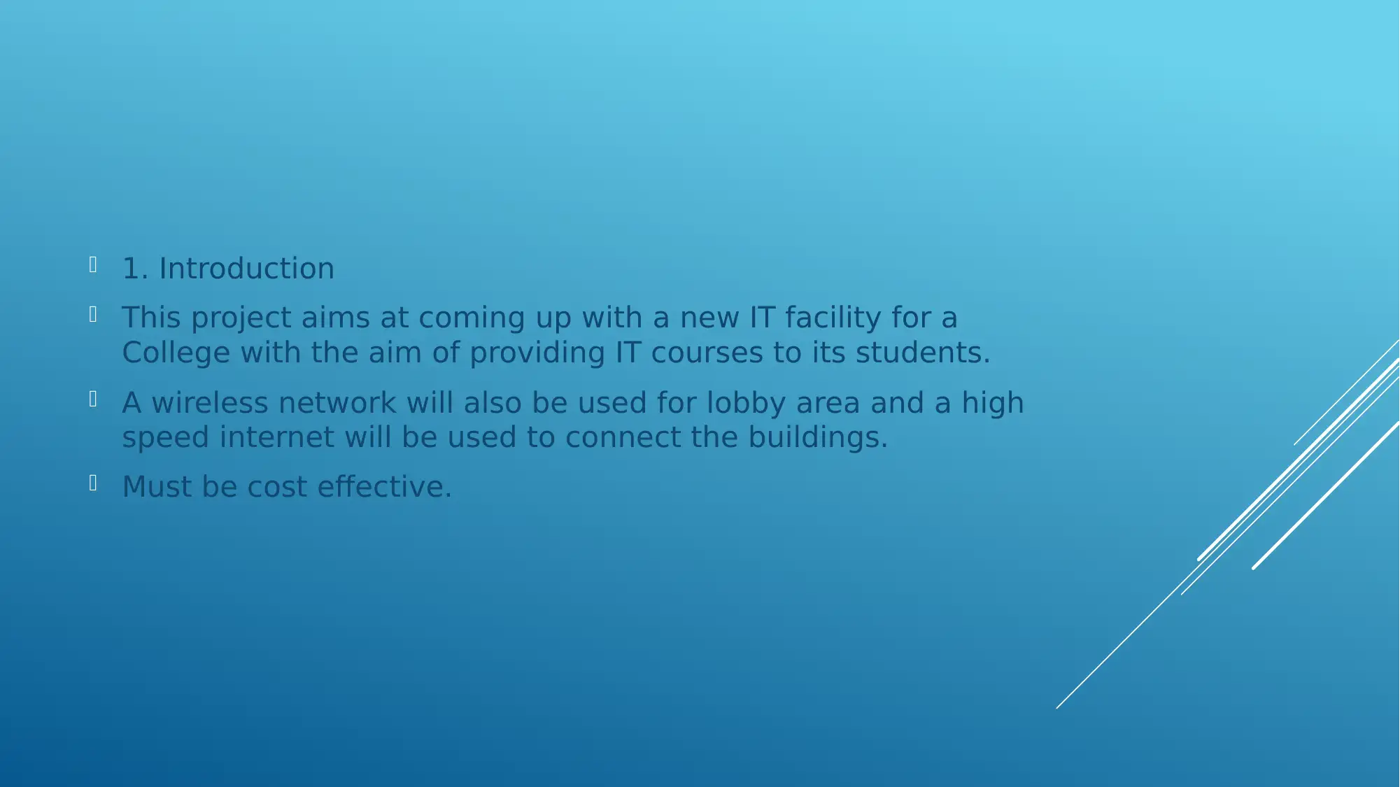
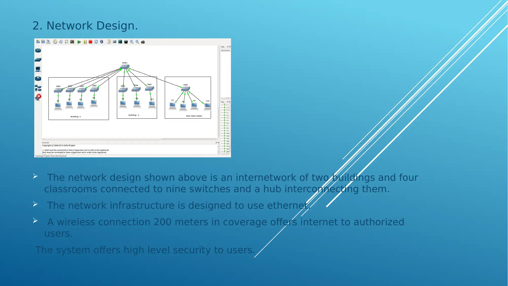
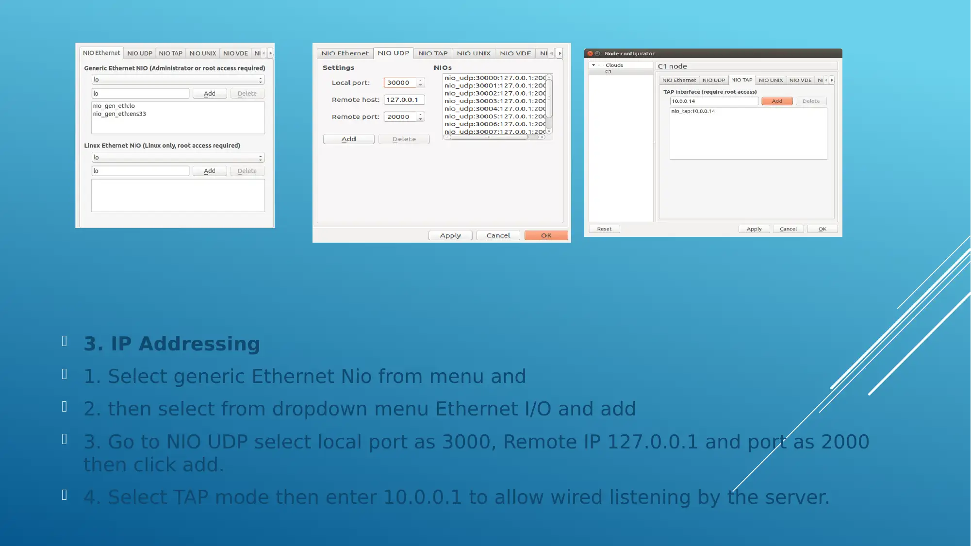
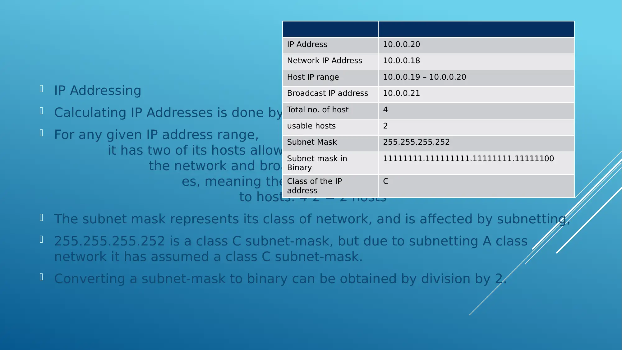
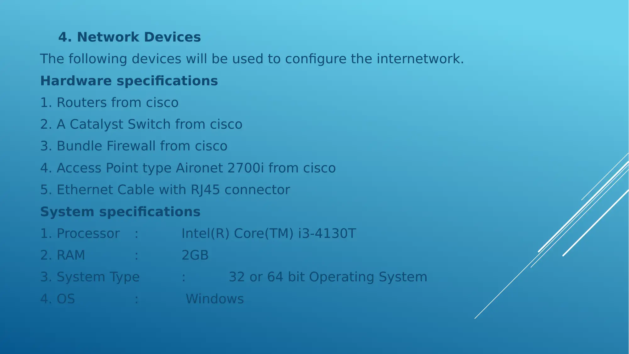
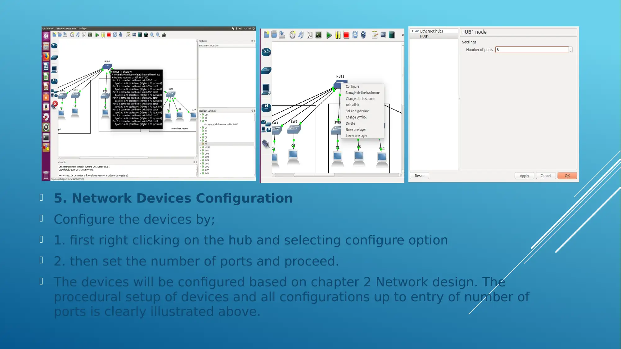
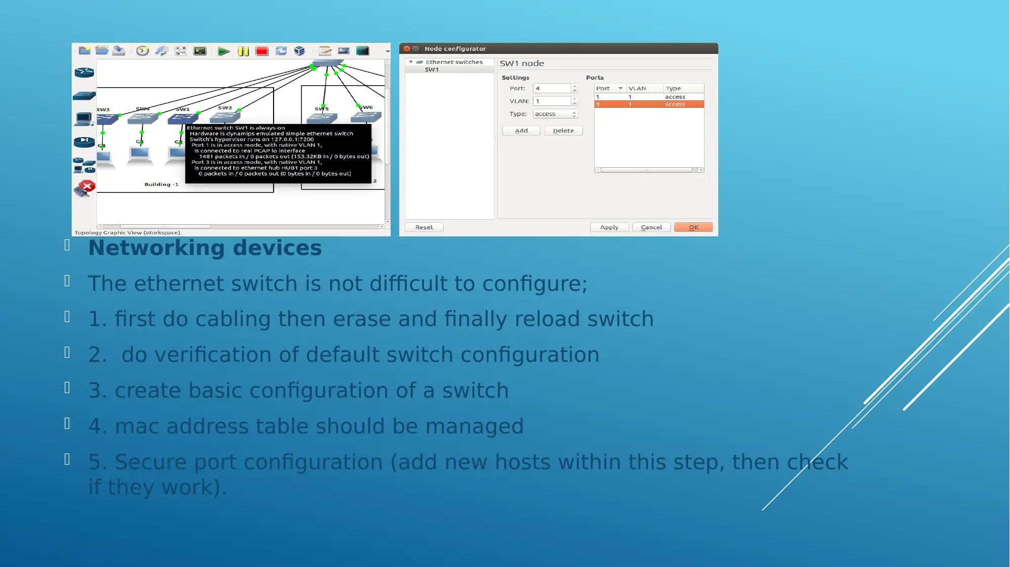
This project outlines the design of a new IT facility for a college, focusing on providing IT courses to students. The design incorporates a wireless network for the lobby area and a high-speed internet connection to link buildings, emphasizing cost-effectiveness. The network design includes two buildings and four classrooms connected via nine switches and a hub, utilizing Ethernet infrastructure. The configuration details IP addressing, subnetting, and the selection of network devices such as Cisco routers, Catalyst switches, bundle firewalls, and Aironet access points. The project also covers the configuration of these devices, including setting up ports and securing the network, with references to relevant patents and publications.

ADVANCED NETWORK
DESIGN
DESIGN
Paraphrase This Document
Need a fresh take? Get an instant paraphrase of this document with our AI Paraphraser

TABLE OF CONTENTS
1. Introduction ……………………………………………………….
2. Network design ………………………………………………......
3. IP addressing ……………………………………………………...
4. Network design …………………………………………………...
5. Network design configuration …………………………….......
6. Conclusion ………………………………………………………...
References ……………………………………………………………
1. Introduction ……………………………………………………….
2. Network design ………………………………………………......
3. IP addressing ……………………………………………………...
4. Network design …………………………………………………...
5. Network design configuration …………………………….......
6. Conclusion ………………………………………………………...
References ……………………………………………………………

1. Introduction
This project aims at coming up with a new IT facility for a
College with the aim of providing IT courses to its students.
A wireless network will also be used for lobby area and a high
speed internet will be used to connect the buildings.
Must be cost effective.
This project aims at coming up with a new IT facility for a
College with the aim of providing IT courses to its students.
A wireless network will also be used for lobby area and a high
speed internet will be used to connect the buildings.
Must be cost effective.
⊘ This is a preview!⊘
Do you want full access?
Subscribe today to unlock all pages.

Trusted by 1+ million students worldwide

2. Network Design.
The network design shown above is an internetwork of two buildings and four
classrooms connected to nine switches and a hub interconnecting them.
The network infrastructure is designed to use ethernet.
A wireless connection 200 meters in coverage offers internet to authorized
users.
The system offers high level security to users.
Paraphrase This Document
Need a fresh take? Get an instant paraphrase of this document with our AI Paraphraser

3. IP Addressing
1. Select generic Ethernet Nio from menu and
2. then select from dropdown menu Ethernet I/O and add
3. Go to NIO UDP select local port as 3000, Remote IP 127.0.0.1 and port as 2000
then click add.
4. Select TAP mode then enter 10.0.0.1 to allow wired listening by the server.
1. Select generic Ethernet Nio from menu and
2. then select from dropdown menu Ethernet I/O and add
3. Go to NIO UDP select local port as 3000, Remote IP 127.0.0.1 and port as 2000
then click add.
4. Select TAP mode then enter 10.0.0.1 to allow wired listening by the server.

IP Addressing
As seen earlier, the steps can then be altered for each new switch being
configured, however, notice, only the TAP interface changes.
Why? Its because the sever uses this IP address to direct traffic to the
right switch not forgetting that the process must be identified by the port
numbers for the host and remote ports.
⊘ This is a preview!⊘
Do you want full access?
Subscribe today to unlock all pages.

Trusted by 1+ million students worldwide

IP Addressing
Calculating IP Addresses is done by;
For any given IP address range,
it has two of its hosts allowed for
the network and broadcast address
es, meaning they are not assigned
to hosts. 4-2 = 2 hosts
The subnet mask represents its class of network, and is affected by subnetting,
255.255.255.252 is a class C subnet-mask, but due to subnetting A class
network it has assumed a class C subnet-mask.
Converting a subnet-mask to binary can be obtained by division by 2.
IP Address 10.0.0.20
Network IP Address 10.0.0.18
Host IP range 10.0.0.19 – 10.0.0.20
Broadcast IP address 10.0.0.21
Total no. of host 4
usable hosts 2
Subnet Mask 255.255.255.252
Subnet mask in
Binary
11111111.111111111.11111111.11111100
Class of the IP
address
C
Paraphrase This Document
Need a fresh take? Get an instant paraphrase of this document with our AI Paraphraser

4. Network Devices
The following devices will be used to configure the internetwork.
Hardware specifications
1. Routers from cisco
2. A Catalyst Switch from cisco
3. Bundle Firewall from cisco
4. Access Point type Aironet 2700i from cisco
5. Ethernet Cable with RJ45 connector
System specifications
1. Processor : Intel(R) Core(TM) i3-4130T
2. RAM : 2GB
3. System Type : 32 or 64 bit Operating System
4. OS : Windows

5. Network Devices Configuration
Configure the devices by;
1. first right clicking on the hub and selecting configure option
2. then set the number of ports and proceed.
The devices will be configured based on chapter 2 Network design. The
procedural setup of devices and all configurations up to entry of number of
ports is clearly illustrated above.
⊘ This is a preview!⊘
Do you want full access?
Subscribe today to unlock all pages.

Trusted by 1+ million students worldwide

Networking devices
The ethernet switch is not difficult to configure;
1. first do cabling then erase and finally reload switch
2. do verification of default switch configuration
3. create basic configuration of a switch
4. mac address table should be managed
5. Secure port configuration (add new hosts within this step, then check
if they work).
Paraphrase This Document
Need a fresh take? Get an instant paraphrase of this document with our AI Paraphraser

References
1. S Ambe, A Johnson, M Kalkunte - US Patent 6,839,349,
2005
Mirroring in a stacked network switch configuration
2. BA Spinney, RJ Simcoe, RE Thomas… - US Patent …, 1995
Packet format in hub for packet data communications system
3. FE Ross - US Patent 5,394,402, 1995
Hub for segmented virtual local area network with shared media access
4. FM Anton Jr, R Marathe - US Patent 7,006,467, 2006
Method and system for simulating multiple independent client devices
in a wired or wireless network
1 out of 11
Related Documents

Your All-in-One AI-Powered Toolkit for Academic Success.
+13062052269
info@desklib.com
Available 24*7 on WhatsApp / Email
Unlock your academic potential
Copyright © 2020–2025 A2Z Services. All Rights Reserved. Developed and managed by ZUCOL.