Assignment 2: Network Design for Modern Software Development Company
VerifiedAdded on 2023/03/17
|17
|2943
|23
Report
AI Summary
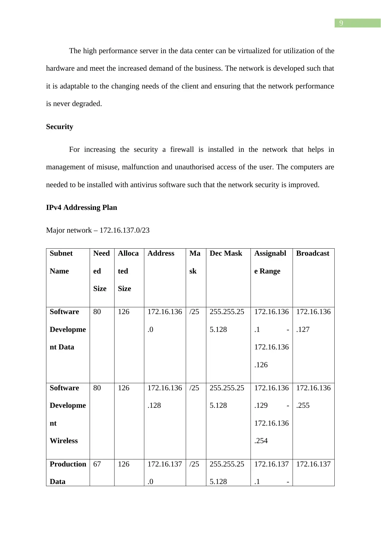
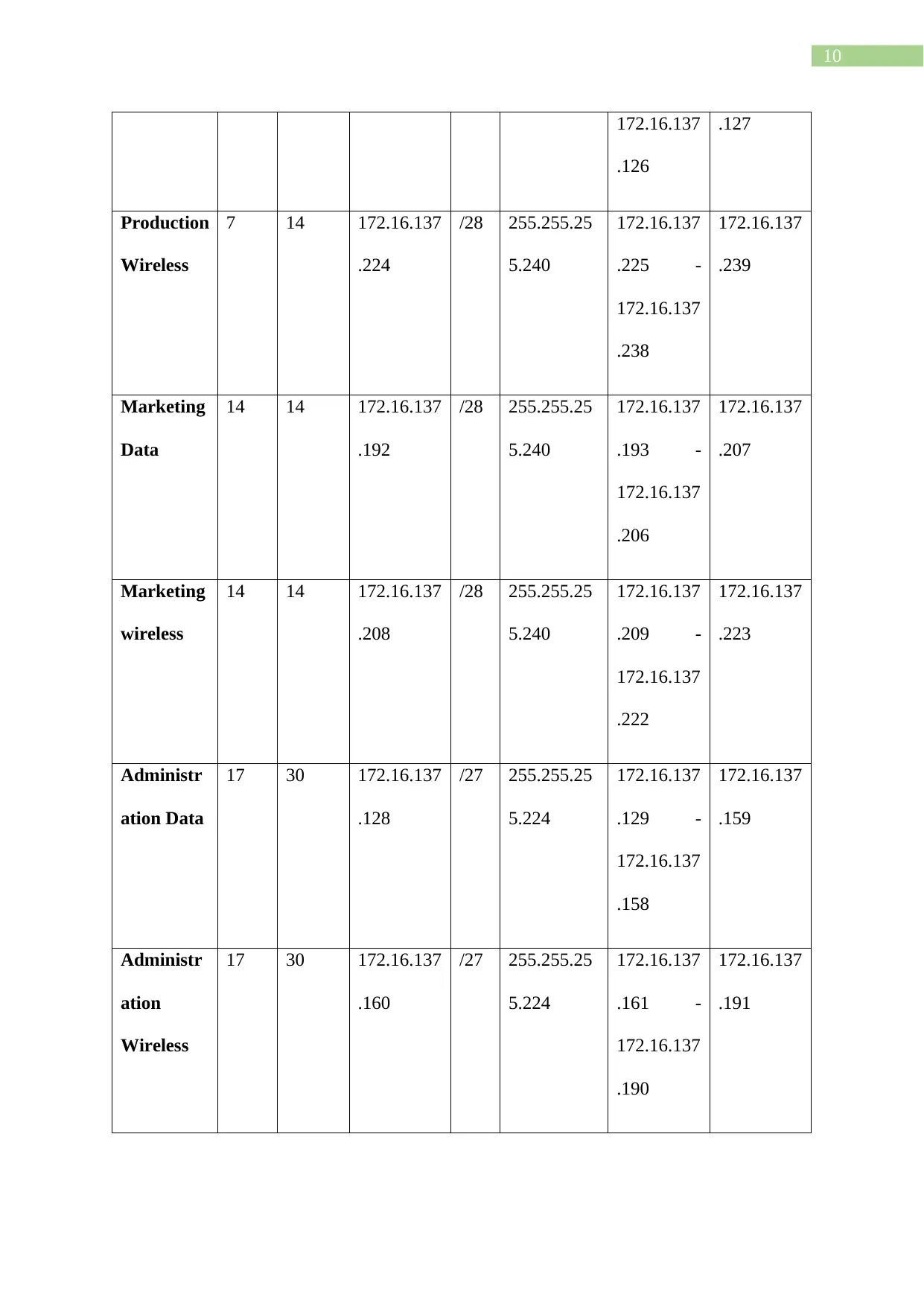
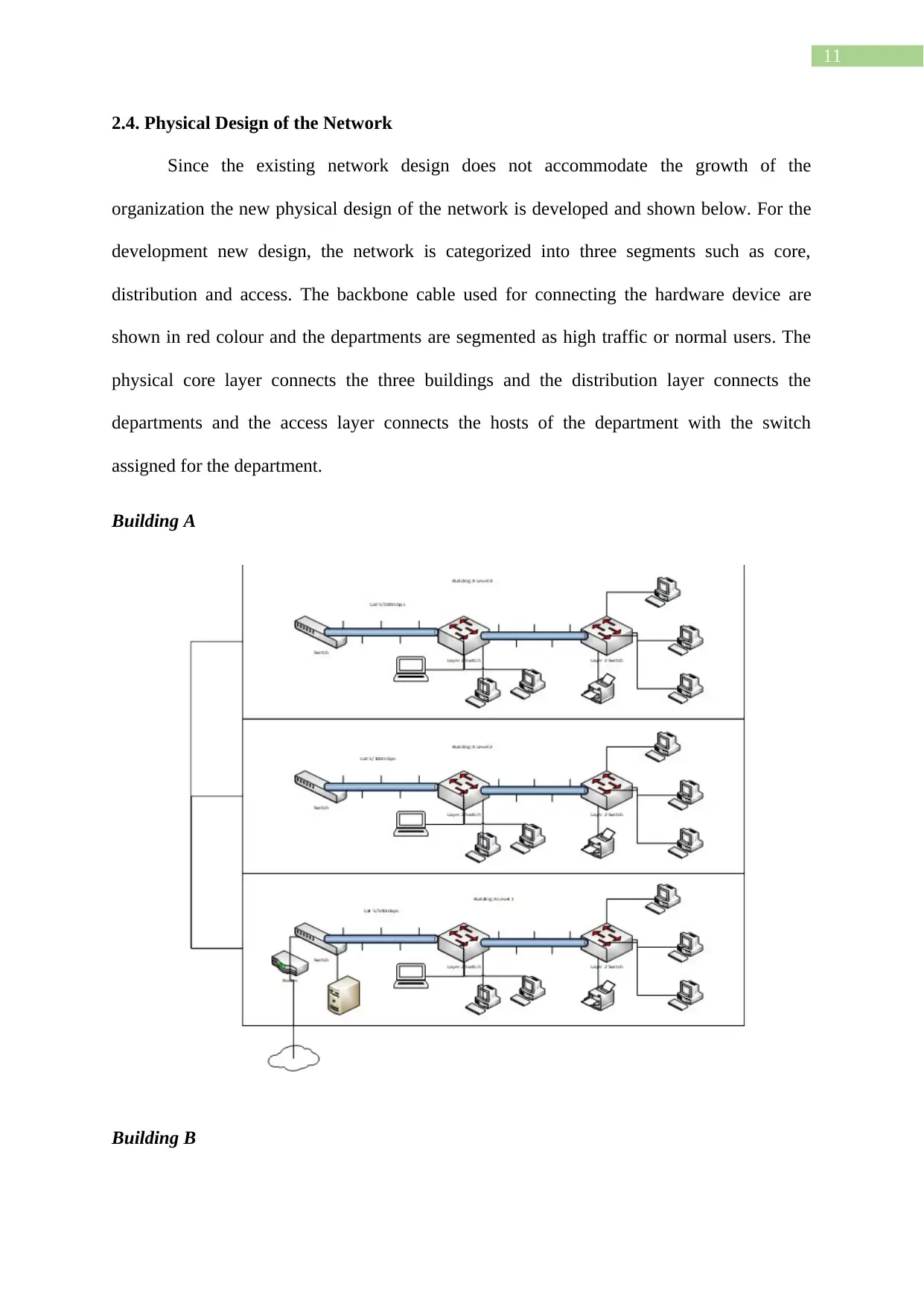
This report provides a comprehensive network design for Advanced Medicos Limited (AML), a digital health company seeking to upgrade its network infrastructure. The report begins with an executive summary outlining the project's purpose, background, and scope, followed by a detailed analysis of AML's current network limitations. The core of the report focuses on the proposed network design, including data transmission media (fiber optic and UTP cables), hardware requirements (Layer 3 switches, high-end servers), and a logical and physical network design based on an extended star topology, incorporating VLANs for department segmentation and addressing BYOD policies. The report details an IPv4 addressing plan and provides justification for design choices, emphasizing performance, extensibility, scalability, and security. It concludes with recommendations for network upgrades, including replacing the file transfer mechanism, implementing a firewall, and incorporating disaster recovery solutions to enhance network efficiency and security. The report utilizes Harvard referencing and includes a table of contents, figures, and tables for clarity and organization.

Assignment 2
Network Design for a Modern Software Development Company
Name of the Student
Name of the University
Author’s Note
Network Design for a Modern Software Development Company
Name of the Student
Name of the University
Author’s Note
Paraphrase This Document
Need a fresh take? Get an instant paraphrase of this document with our AI Paraphraser

1
Executive Summary
AML have the requirement to upgrade their current network solution such that it can
accommodate the organizations future needs and expand their business. The current building
framework of the organization is evaluated for dividing the network with VLANs according
to the name of the department. The building floorplan of three adjacent building of the
company is analysed for identifying the number of wireless routing device is needed to be
installed for enabling the company to support BYOD policy. A new network framework is
created for the organization after the evaluation of the security needs. The data transmission
media and the essential hardware device required for the development of the network
framework is recognized for creating the network design. An Ipv4 addressing plan is created
following the number of subnets needed for the development and the Ip addressing table is
created for the development of the network framework.

2
Table of Contents
1. Introduction............................................................................................................................3
1.1. Purpose............................................................................................................................3
1.2. Background.....................................................................................................................3
1.3. Scope of the Project........................................................................................................3
2. Network Design for Recommended Network........................................................................4
2.1. Data Transmission Media...............................................................................................4
2.2. Hardware requirement.....................................................................................................5
2.3. Logical Design of the Network.......................................................................................6
2.4. Physical Design of the Network....................................................................................11
4. Conclusion............................................................................................................................12
5. Recommendations................................................................................................................13
Bibliography.............................................................................................................................15
⊘ This is a preview!⊘
Do you want full access?
Subscribe today to unlock all pages.

Trusted by 1+ million students worldwide

3
1. Introduction
1.1. Purpose
The report is developed for identifying the current bottleneck conditions of existing
Advanced Medicos Limited network and a suggest a solution for eliminating the bottleneck
and upgrade the current network infrastructure. The business and technical goals is evaluated
for the deployment of the organizational network.
1.2. Background
Advanced Medicos Limited (AML) sells different types of healthcare product and the
main products include hardware used for providing different types of health services. It is a
digital health company that currently have the need for upgrading their current network and
leave room such that future expansion is allowed and the network can meet the needs for the
upcoming five years. An analysis is made on the future needs such that the flaws in the
current design is identified and the network solution is developed aligning the needs of the
organization. The network needs to support BYOD and remote connection for the employees
such that they can access the network from different geographical location.
1.3. Scope of the Project
The increase in the users for each of the departments is estimated for the calculating
the IP address and subnet that are needed for configuring the network. The wireless needs of
the network and expected number of user using the wireless solution is also identified for
creating a separate subnet for the wireless network and allow the user to bring their own
device and connect it with the organizational network such that their performance can be
increased (Dong et al. 2015). An evaluation is made on the data transmission media and the
hardware identified for its implementation in the proposed network solution of AML. The
security that are needed to be enforced for increasing the efficiency and performance of the
Paraphrase This Document
Need a fresh take? Get an instant paraphrase of this document with our AI Paraphraser

4
network is evaluated such that the information of the company are kept secured and the risk
of unauthorised access is eliminated.
2. Network Design for Recommended Network
2.1. Data Transmission Media
Optical fibre cable is needed to be used for interconnecting each of the three adjacent
building and replacing the existing the Web portal connection. The adjacent buildings are
located at 40-meter distance that allows connection with the datacentre and the fibre optics
cable should be cut at a length of 50 m (White 2015). The cost of cabling includes the
installation charge and the cost of the cable. UTP category 6 cables are needed to be used for
interconnecting the nodes with each other in the local area network for each of the
department of the building.
The use of the dedicated link and replacing the VPN connection for connecting each
of the department or buildings can improve the resource sharing efficiency (Yang, Deng and
Liu 2015). The efficiency of sharing resources and reliability is important for meeting the
aims and objectives of AML. The software development team working in the organization
has the need for exchanging data and information at a high sped such that their productivity is
improved and the current VPN causes a bottleneck because the internet speed is used for
transferring the data. The utilization of the available bandwidth of the internet causes
decrease the performance of the network (Wollschlaeger, Sauter and Jasperneite 2017). It is
estimated that with the growth of the company the requirement would also increase and a
reliable communication is needed to be established for exchanging information between the
different representment working on the three adjacent buildings. The datacentre is needed to
be connected using the fibre optics link for enabling for increasing the bandwidth to 10 gbps
for each of the floors in the building (Stallings 2017). The cabling used for connecting the

5
department need to support gigabit ethernet and since cat 6 cables are used they are not
needed to be replaced and thus does not incur extra cost in the project.
2.2. Hardware requirement
The current network setup of AML uses layer 2 switches and they are needed to be
replaced in the core layer with layer 3 switch such that the routes can be managed and VLAN
information can be distributed efficiently with the layer 2 switches. The layer 3 switches
should have 48 ports and replace the main switch for each of the floor. It is also needed to be
used as a backbone switch for the datacentre and thus an SFP module is needed to be
installed for connecting the fibres (Kralicek 2016). For each of the layer 3 switch a SFP
module is needed to be installed such that it can be connected with the switches in each of the
floor. High end servers are also needed that can be virtualized for handling the loads of the
user request. The hardware specification for the server is given below:
Server Model – Lenovo ThinkStation P920 Tower Workstation
Motherboard – Socket: FCLGA3647 Type: NSBM
Processor – 2.3 GHz Intel Xeon Gold 5118 12-Core
Memory – 16 Gb DDR4
Storage - Minimum 500 Gb or above
Operating System – Windows Server 2016
NIC - 2 x 10/100/1000 Mb/s Gigabit Ethernet (RJ45)
Virtual OS – vSphere VMWare
The existing service that are configured in the network is needed to be moved to the high
end server and it is needed to be located at the data centre of the building. A secondary server
is needed to be installed for acting as a disaster recovery and help in interconnecting the
business and the department can use the server for recovering their data.
⊘ This is a preview!⊘
Do you want full access?
Subscribe today to unlock all pages.

Trusted by 1+ million students worldwide

6
Currently the ports available in the switches cannot meet the scalability for expanding the
network in future and additional switches are needed to be installed in the network for
allowing the growth of the organization. Since the lost of layer 3 switches is reducing with
the increase in their use they can be used more such that capacity and network performance
can be improved (Hadinoto, Noertjahyana and Purba 2018). An appropriate technology is
needed to be selected such that the productivity can be boosted and connecting additional
switches helps in improving the scalability of the proposed network infrastructure.
Cost benefit analysis
Cost
Benefit
2.3. Logical Design of the Network
An extended star topology is followed for the development of the network and the
following diagram demonstrates the layout of each of the floors in the building and grouping
Paraphrase This Document
Need a fresh take? Get an instant paraphrase of this document with our AI Paraphraser

7
according to the departments. The departments utilizing high bandwidth are connected with
redundant link and interconnection between the buildings are shown below.
Building A
Building B
according to the departments. The departments utilizing high bandwidth are connected with
redundant link and interconnection between the buildings are shown below.
Building A
Building B

8
Justification
Performance
The above diagram helps in increasing the performance because redundant link and
layer 3 device are used for enabling gigabyte Ethernet and thus increasing the bandwidth for
sharing large files between the two buildings.
Extensibility
The network is created such that new device can be added to the access layer for
meeting the growth of the organization. The two data centres in the two buildings are merged
to form a single data centre and high performance servers are used such that wide range of
service can be provided to the user.
Scalability
⊘ This is a preview!⊘
Do you want full access?
Subscribe today to unlock all pages.

Trusted by 1+ million students worldwide

9
The high performance server in the data center can be virtualized for utilization of the
hardware and meet the increased demand of the business. The network is developed such that
it is adaptable to the changing needs of the client and ensuring that the network performance
is never degraded.
Security
For increasing the security a firewall is installed in the network that helps in
management of misuse, malfunction and unauthorised access of the user. The computers are
needed to be installed with antivirus software such that the network security is improved.
IPv4 Addressing Plan
Major network – 172.16.137.0/23
Subnet
Name
Need
ed
Size
Alloca
ted
Size
Address Ma
sk
Dec Mask Assignabl
e Range
Broadcast
Software
Developme
nt Data
80 126 172.16.136
.0
/25 255.255.25
5.128
172.16.136
.1 -
172.16.136
.126
172.16.136
.127
Software
Developme
nt
Wireless
80 126 172.16.136
.128
/25 255.255.25
5.128
172.16.136
.129 -
172.16.136
.254
172.16.136
.255
Production
Data
67 126 172.16.137
.0
/25 255.255.25
5.128
172.16.137
.1 -
172.16.137
Paraphrase This Document
Need a fresh take? Get an instant paraphrase of this document with our AI Paraphraser

10
172.16.137
.126
.127
Production
Wireless
7 14 172.16.137
.224
/28 255.255.25
5.240
172.16.137
.225 -
172.16.137
.238
172.16.137
.239
Marketing
Data
14 14 172.16.137
.192
/28 255.255.25
5.240
172.16.137
.193 -
172.16.137
.206
172.16.137
.207
Marketing
wireless
14 14 172.16.137
.208
/28 255.255.25
5.240
172.16.137
.209 -
172.16.137
.222
172.16.137
.223
Administr
ation Data
17 30 172.16.137
.128
/27 255.255.25
5.224
172.16.137
.129 -
172.16.137
.158
172.16.137
.159
Administr
ation
Wireless
17 30 172.16.137
.160
/27 255.255.25
5.224
172.16.137
.161 -
172.16.137
.190
172.16.137
.191
172.16.137
.126
.127
Production
Wireless
7 14 172.16.137
.224
/28 255.255.25
5.240
172.16.137
.225 -
172.16.137
.238
172.16.137
.239
Marketing
Data
14 14 172.16.137
.192
/28 255.255.25
5.240
172.16.137
.193 -
172.16.137
.206
172.16.137
.207
Marketing
wireless
14 14 172.16.137
.208
/28 255.255.25
5.240
172.16.137
.209 -
172.16.137
.222
172.16.137
.223
Administr
ation Data
17 30 172.16.137
.128
/27 255.255.25
5.224
172.16.137
.129 -
172.16.137
.158
172.16.137
.159
Administr
ation
Wireless
17 30 172.16.137
.160
/27 255.255.25
5.224
172.16.137
.161 -
172.16.137
.190
172.16.137
.191

11
2.4. Physical Design of the Network
Since the existing network design does not accommodate the growth of the
organization the new physical design of the network is developed and shown below. For the
development new design, the network is categorized into three segments such as core,
distribution and access. The backbone cable used for connecting the hardware device are
shown in red colour and the departments are segmented as high traffic or normal users. The
physical core layer connects the three buildings and the distribution layer connects the
departments and the access layer connects the hosts of the department with the switch
assigned for the department.
Building A
Building B
⊘ This is a preview!⊘
Do you want full access?
Subscribe today to unlock all pages.

Trusted by 1+ million students worldwide
1 out of 17
Related Documents

Your All-in-One AI-Powered Toolkit for Academic Success.
+13062052269
info@desklib.com
Available 24*7 on WhatsApp / Email
Unlock your academic potential
Copyright © 2020–2025 A2Z Services. All Rights Reserved. Developed and managed by ZUCOL.