Network Design and Implementation Report: Assessment 3 & 4

Verified

Added on  2022/09/18

|22
|1732
|20
Report
AI Summary
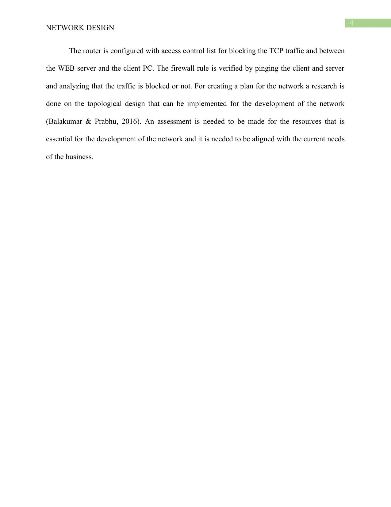
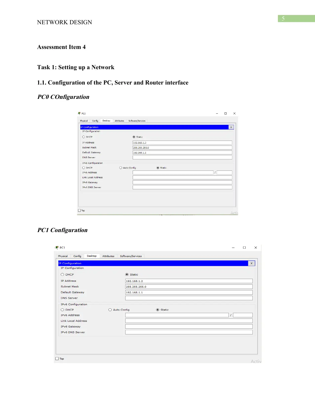
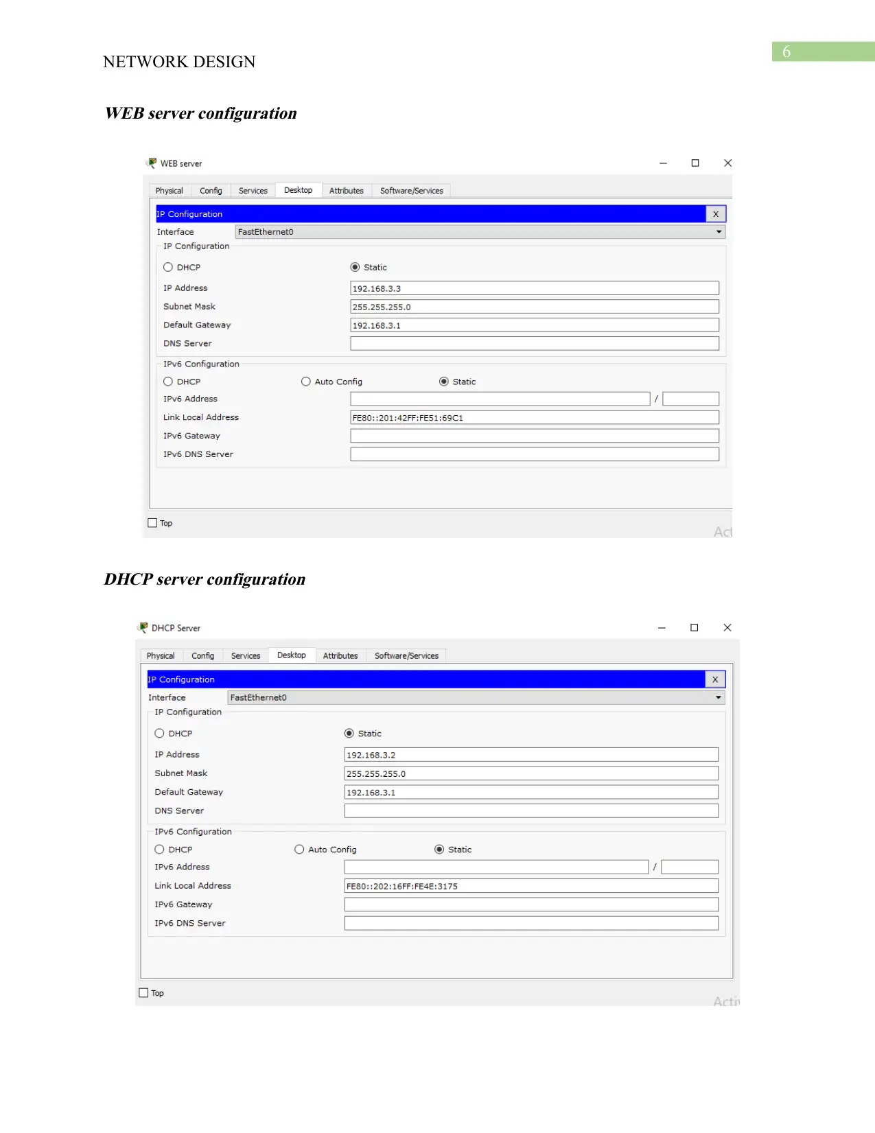
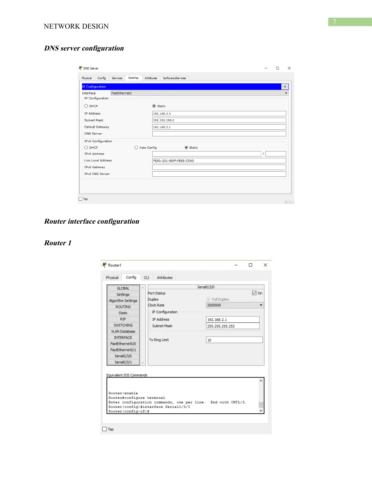
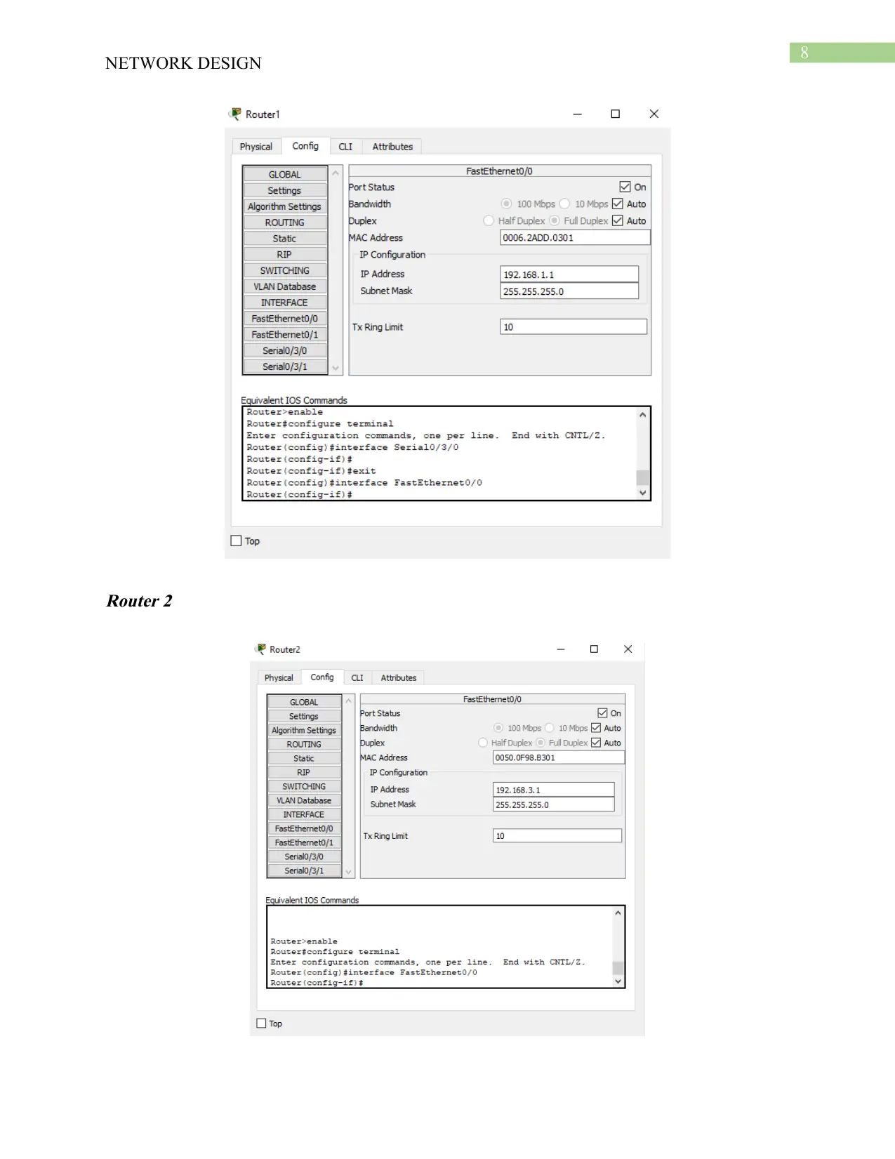
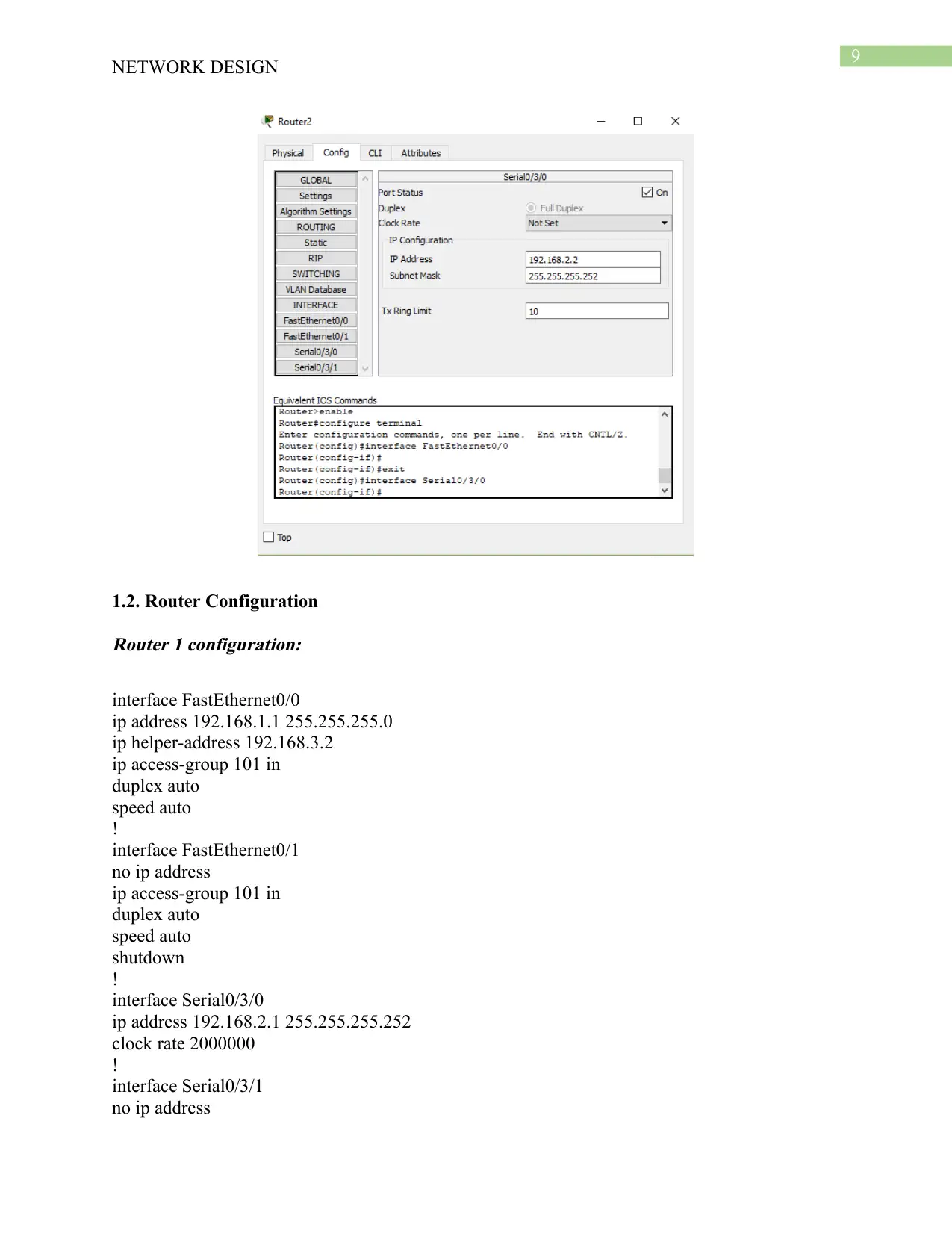
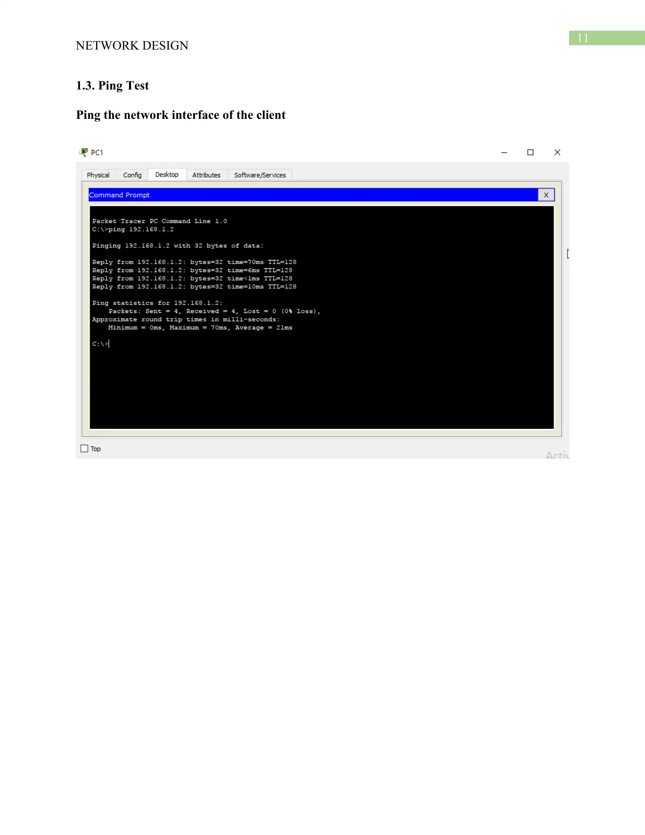
This report details a network design project, encompassing Assessments 3 and 4. The student utilized Packet Tracer to simulate and configure a network, focusing on router configuration using RIP, DHCP server setup for dynamic IP address allocation, DNS server configuration for domain name resolution, and firewall implementation to control network traffic. The report outlines the network topology, including PCs, routers, switches, and servers, and provides detailed configuration steps for each component. It includes screenshots and ping/traceroute tests to demonstrate the functionality of the network. The student also addresses the limitations of the design, such as the absence of wireless access points, and discusses the top-down network design approach used. The report concludes with a summary of the implemented configurations and a bibliography of cited sources.
Document Page
Running head: NETWORK DESIGN
Network Design
Name of the Student
Name of the University
Author’s Note
tabler-icon-diamond-filled.svg

Secure Best Marks with AI Grader

Need help grading? Try our AI Grader for instant feedback on your assignments.
Document Page
1
NETWORK DESIGN
Table of Contents
Assessment Item 3...........................................................................................................................2
Assessment Item 4...........................................................................................................................5
Task 1: Setting up a Network..........................................................................................................5
1.1. Configuration of the PC, Server and Router interface..........................................................5
1.2. Router Configuration............................................................................................................9
1.3. Ping Test.............................................................................................................................11
1.4. Tracerouting from client to server......................................................................................15
Task 2- Network Service Configuration........................................................................................16
2.1. DHCP..................................................................................................................................16
2.2. WEB Server........................................................................................................................16
2.3. DNS....................................................................................................................................17
2.4. Firewall...............................................................................................................................18
Assignment 4 Summary.................................................................................................................19
Bibliography..................................................................................................................................21
Document Page
2
NETWORK DESIGN
Assessment Item 3
The following steps are needed to be performed for the development of the network:
Network topological design: The placement of the network hardware components and
connecting them with each other is needed to be determined. The design is needed to be
optimized such that shortest path is used for transmitting data between the source and the
destination address (Bertasius, Shi & Torresani, 2015). The cost for transmission of data packet
is needed to be kept minimum and cost of switching is also needed to be kept minimum for
increasing the efficiency of the network.
Network Synthesis: The criteria of performance of the network and analysis of the
component size is important. The network is also needed to be segmented and the wastage of Ip
address is needed to be reduced for increasing the efficiency and performance of the network.
Selection of appropriate network topology is important and cost of transmission is needed to be
kept minimum such that the response of the network is higher.
Network Realization: The capacity needs of the network that is needed to be fulfilled is
needed to be identified and the reliability of the network is needed to be ensured. The flow of
data packet is needed to be optimized and the information related with demand, cost, bandwidth
requirement is needed to be calculated and the physical circuit plan is needed to be created
(Shrivastava et al., 2016).
The prototype of the network is created in packet tracer and configured with appropriate
network protocol and technology for demonstration of the network design. The main cons of the
developed network in assessment 4 is that it does not have any wireless access point and thus
does not support any wireless device to be connected with the network.
Document Page
3
NETWORK DESIGN
For the development of the network an assessment is done on the hardware devices that
are needed to be selected for enabling transmission of data packets between the client and the
server. A top down network design approach is followed for the development of the network.
Focus is given on the specific goals and required network service and application for the
development of the network (Chou, Baker & Vega-Herrera, 2016). The main disadvantage of the
approach is that a thorough analysis is needed to be made for determining the specific user
requirement and it is needed to be ensured that all the possible application and services are
considered.
The network is setup with PC, router, switches and server and dynamic routing protocol
is utilized for configuring the route between the client and the server. Different network address
are used for configuring the interface of the router and enabling transmission of data packets
between the end nodes connected with the different interface of the routers. The routers are
connected with each other with serial link and for the distribution of the network the fast
Ethernet port is connected with a layer 3 switch. The interface of the router is configured with an
IP address and it is used for the configuration of the host as default gateway and send and receive
data packet via the interface (Archana, 2015). The data packets are transmitted via the default
gateway and static IP address is used for configuring route and reach the destination address. The
router protocols and configuration is checked by pinging the local and the remote router gateway
interface and the traceroute command is used for identifying the route used for reaching the
destination address. A DHCP server is configured by creating pool of IP address and allowing
the host connected in the network for assigning of IP address, subnet and DNS address from the
server automatically. A server is configured with web service for and DNS for allowing the user
to use URL instead of IP address to access the server.
tabler-icon-diamond-filled.svg

Secure Best Marks with AI Grader

Need help grading? Try our AI Grader for instant feedback on your assignments.
Document Page
4
NETWORK DESIGN
The router is configured with access control list for blocking the TCP traffic and between
the WEB server and the client PC. The firewall rule is verified by pinging the client and server
and analyzing that the traffic is blocked or not. For creating a plan for the network a research is
done on the topological design that can be implemented for the development of the network
(Balakumar & Prabhu, 2016). An assessment is needed to be made for the resources that is
essential for the development of the network and it is needed to be aligned with the current needs
of the business.
Document Page
5
NETWORK DESIGN
Assessment Item 4
Task 1: Setting up a Network
1.1. Configuration of the PC, Server and Router interface
PC0 COnfiguration
PC1 Configuration
Document Page
6
NETWORK DESIGN
WEB server configuration
DHCP server configuration
tabler-icon-diamond-filled.svg

Paraphrase This Document

Need a fresh take? Get an instant paraphrase of this document with our AI Paraphraser
Document Page
7
NETWORK DESIGN
DNS server configuration
Router interface configuration
Router 1
Document Page
8
NETWORK DESIGN
Router 2
Document Page
9
NETWORK DESIGN
1.2. Router Configuration
Router 1 configuration:
interface FastEthernet0/0
ip address 192.168.1.1 255.255.255.0
ip helper-address 192.168.3.2
ip access-group 101 in
duplex auto
speed auto
!
interface FastEthernet0/1
no ip address
ip access-group 101 in
duplex auto
speed auto
shutdown
!
interface Serial0/3/0
ip address 192.168.2.1 255.255.255.252
clock rate 2000000
!
interface Serial0/3/1
no ip address
tabler-icon-diamond-filled.svg

Secure Best Marks with AI Grader

Need help grading? Try our AI Grader for instant feedback on your assignments.
Document Page
10
NETWORK DESIGN
clock rate 2000000
!
interface Vlan1
no ip address
shutdown
!
router rip
version 2
network 192.168.1.0
network 192.168.2.0
network 192.168.3.0
no auto-summary
Router 2 configuration:
interface FastEthernet0/0
ip address 192.168.3.1 255.255.255.0
duplex auto
speed auto
!
interface FastEthernet0/1
no ip address
ip helper-address 192.168.2.1
duplex auto
speed auto
!
interface Serial0/3/0
ip address 192.168.2.2 255.255.255.252
!
interface Serial0/3/1
no ip address
clock rate 2000000
!
interface Vlan1
no ip address
shutdown
!
router rip
version 2
network 192.168.2.0
network 192.168.3.0
no auto-summary
Document Page
11
NETWORK DESIGN
1.3. Ping Test
Ping the network interface of the client
Document Page
12
NETWORK DESIGN
Pinging test of local router gateway
Pinging test of remote router
tabler-icon-diamond-filled.svg

Paraphrase This Document

Need a fresh take? Get an instant paraphrase of this document with our AI Paraphraser
Document Page
13
NETWORK DESIGN
Pinging test of server
Document Page
14
NETWORK DESIGN
Document Page
15
NETWORK DESIGN
1.4. Tracerouting from client to server
tabler-icon-diamond-filled.svg

Secure Best Marks with AI Grader

Need help grading? Try our AI Grader for instant feedback on your assignments.
Document Page
16
NETWORK DESIGN
Task 2- Network Service Configuration
2.1. DHCP
2.2. WEB Server
Document Page
17
NETWORK DESIGN
2.3. DNS
Document Page
18
NETWORK DESIGN
2.4. Firewall
Configuration of Router 1:
access-list 101 deny tcp host 192.168.1.2 host 192.168.3.6 eq www
access-list 101 permit ip any any
access-list 10 deny host 192.168.1.2
access-list 10 permit any
tabler-icon-diamond-filled.svg

Paraphrase This Document

Need a fresh take? Get an instant paraphrase of this document with our AI Paraphraser
Document Page
19
NETWORK DESIGN
Assignment 4 Summary
For the configuration of the network design we have used packet tracer and following the
instructions of the requirement for setting up the network. Two 2811 series routers are used and
they are interconnected with serial interface. The router 1 fast Ethernet interface is connected
with a switch for connecting the two PCs. The router 2 fast Ethernet interface is connected with a
switch for connecting with the servers. The address of 192.168.0.0 is used for allocation of IP
address to each of the interface of the network devices. The routing configuration is made in the
router with the use of RIP and for allocation of DHCP address to the PC connected with router 1
interface IP helper command followed by the IP address of the DHCP server address is used such
that the PCs automatically gets assigned with the IP address. For testing the configuration a ping
test is conducted to different interfaces of the network device. The network service are
configured with the configuration of WEB server, DNS server, DHCP server and Firewall
Document Page
20
NETWORK DESIGN
configuration. Screenshots are attached with the report for the demonstration of the steps taken
for the configuration of the servers. In the DHCP server a pool is created with the address range
that is needed to be assigned to the PCs, DNS server address and is tested by setting the PC to
DHCP for getting IP address from the DHCP server. The WEB server is configured with URL
for the IP address of the DNS server such that the client PC can reach the server using the IP
address and the URL. The router is then configured with access control list for filtering the
traffic and blocking the HTTP traffic between the WEB server. The configuration is done in
router1 and applied in fast Ethernet interface for the management of access of the network
traffic.
Document Page
21
NETWORK DESIGN
Bibliography
Archana, C. (2015). Analysis of RIPv2, OSPF, EIGRP Configuration on router Using CISCO
Packet tracer. International journal of Engineering science and innovative technology
(IJESIT) volume, 4.
Balakumar, N., & Prabhu, B. (2016). Evaluation of Quality in Network and Interoperable
Connectivity between IP Networks. International Journal of Current Engineering and
Scientific Research (IJCESR), 3(9).
Bertasius, G., Shi, J., & Torresani, L. (2015). Deepedge: A multi-scale bifurcated deep network
for top-down contour detection. In Proceedings of the IEEE conference on computer
vision and pattern recognition (pp. 4380-4389).
Chou, T. S., Baker, S., & Vega-Herrera, M. (2016, June). A comparison of network simulation
and emulation virtualization tools. In Proc. ASEE Annu. Conf. Expo. (pp. 1-9).
Rosewell, J., Kear, K., Jones, A., Smith, A., Donelan, H., Mikroyannidis, A., ... & Moss, N.
(2018). Open Networking Lab: online practical learning of computer networking.
Shrivastava, A., Sukthankar, R., Malik, J., & Gupta, A. (2016). Beyond skip connections: Top-
down modulation for object detection. arXiv preprint arXiv:1612.06851.
chevron_up_icon
1 out of 22
circle_padding
hide_on_mobile
zoom_out_icon
logo.png

Your All-in-One AI-Powered Toolkit for Academic Success.

Available 24*7 on WhatsApp / Email

[object Object]