CSC00240 - Report on Network Design for Advanced Medicos Limited (AML)
VerifiedAdded on 2022/11/14
|14
|2237
|317
Report
AI Summary
This report presents a comprehensive network design for Advanced Medicos Limited (AML), a digital health company aiming to upgrade its existing network to support web-based health services. The design incorporates a hierarchical network architecture with Gigabit Ethernet, fiber optic cables for improved bandwidth, and layer 3 switches. The report proposes hardware changes, including the deployment of high-end servers for virtualization and disaster recovery, and software recommendations, emphasizing compatibility with existing applications and cloud storage solutions. An IP addressing plan is also included. The report justifies the proposed changes in terms of cost-benefit analysis, scalability, and enhanced network performance, ensuring that the network can accommodate current and future needs while maintaining security and efficiency. The network topology includes logical and physical diagrams, detailing the layout and connectivity of the network infrastructure.
Running head: DATA COMMUNICATION AND NETWORKS
Data Communication and Networks
Name of the Student
Name of the University
Author’s Note
Data Communication and Networks
Name of the Student
Name of the University
Author’s Note
Paraphrase This Document
Need a fresh take? Get an instant paraphrase of this document with our AI Paraphraser
1
DATA COMMUNICATION AND NETWORKS
Table of Contents
1. Description of Proposed Network...............................................................................................2
1.1. Goals of network design.......................................................................................................2
1.2. Proposed Network Circuits...................................................................................................2
1.3. Proposed Network Hardware................................................................................................3
1.4. Proposed Network Software.................................................................................................5
1.5. Proposed Network Layout....................................................................................................7
2. IP Addressing Plan......................................................................................................................8
3. Conclusion...................................................................................................................................9
References......................................................................................................................................10
Appendix A....................................................................................................................................11
Logical Network Topology........................................................................................................11
Network Physical topology........................................................................................................12
2
DATA COMMUNICATION AND NETWORKS
1. Description of Proposed Network
1.1. Goals of network design
As organizational growth exceeds a certain limit, accommodations might start to lack regarding
needs and services for the users who are there in existing network. For the business to be
competitive and professional, it has to be faster, should be capable in storing and retrieving data
on time constraint manner, it should also be efficient in utilization of resources while providing
secure, stable along with more scalable services.
There has to be various requirement in the building of this network which would require a lot of
investment and it is therefore advisable to reuse the pre-existing infrastructure as far as possible
so that cost could be reduced.
The present network should also be equipped with data recovery mechanism which is very
beneficial in times of data mismanagement or certain situation of disaster which might occur
during any period of time. These recovery tools are very critical and should be utilized in the
network structure.
1.2. Proposed Network Circuits
The previous network structure utilised cables of category 6 and these cables should be reused in
the present network structure.
Suggested circuit changes for proposed network:
VPN tunnel in both the building i.e building one as well as building two has to be replaced by
optical fiber which would yield better results than the previous ones.
⊘ This is a preview!⊘
Do you want full access?
Subscribe today to unlock all pages.
Trusted by 1+ million students worldwide
3
DATA COMMUNICATION AND NETWORKS
Data centres could be connected throughout both the building as the actual distance between
these two building have been found out to be 40m. An estimated length which was found for
proposed optical fiber is 50m. The cost for the overall building of network would also be
including cost for installation of hardware as well as cost for the cables which was deployed.
Justification/Cost benefit:
The replacement for the VPN with the cost of fiber has been justified through following
statements:
The efficiency as well as the effectiveness of the network structure would be enhanced through
the utilisation of fiber links in between buildings which would thereby help in having an impact
which is viable for any disaster recovery situation which might arise in this network.
Gigabit Ethernet could be effectively introducing for each of the building in optical fiber is used.
This would further improve bandwidth of the network upto 10GB for every floor which in itself
will not only provide better network connectivity for its users but will also be instrumental in
increasing the productivity of the organisation.
The present optical fiber would also reduce the overall cost for the deployment of this network
which generally is the cost which is saved because of capital required for re-cabling the whole
network.
The usage of Gigabit services which is available because of hardware which are deployed in the
network structure. This also has no implication on the budget of the network. 802.3ae is support
standard that is available in the Gigabit Ethernet.
1.3. Proposed Network Hardware
Paraphrase This Document
Need a fresh take? Get an instant paraphrase of this document with our AI Paraphraser
4
DATA COMMUNICATION AND NETWORKS
The layer 2 switches have been replaced for the distribution along with access layer in the
network. These switches were deployed in the previous network structure.
Suggested hardware changes for proposed network:
As the layer 3 switches does have more ports (48+24), they have to be deployed in place
of layer 2 switches. The replaced layer 3 switches have to support SFP.
The connections of fiber for both building have to be well communicated by the backbone
which also have been connected by layer 3 switches. SPF module of fiber switch and
connection will be required to execute this interconnect switch.
The increase in amount of the layer 2 switches does also increases SPF addition
requirement modules which is vital to enable connection of switches between floors.
Data center that is situated in the building one have to be utilized through layer 2
switches.
Apart from this, 2 of high end servers needs to be utilized to perform virtualization of
various different servers along with any other functions such as disaster recovery and any
others.
Basic specifications of the two new servers are suggested as:
Model: HP Dl380 G7
Memory: 80GB
Storage capacity: 2TB
Operating System (for each separate logical server): Windows Server 2012
Virtual Operating System: VMWare VSphere
5
DATA COMMUNICATION AND NETWORKS
The various functions of several existing server is to be shifted to other high end servers acting
as the VMWare Host, and it is also located into the data centre of the building one.
All the high-end server which would be acting servers for the disaster recovery is to be installed
in building two. In order to use fiber connections, all the data which is residing in the main server
of building one is to be replicated effectively with the server for the disaster recovery system
which has been deployed in second building. The above process will lead to the availability of
recovery option throughout the day which does enhance the security as well as data utilization of
the network. The interconnectivity mechanism which has been deployed in the two building
would also be ensuring that in certain time of emergency, the machine which has been installed
in second building will effectively stabilize the whole network structure.
Justification/Cost Benefit:
The port numbers which has been provided by layer 2 switches are not enough for all
employees who are working in this company in case if concerned company decides to expand
their business. Therefore, the business has to be equipped with the facility of deploying extra
switches so that it could be utilized in times of need. In cases when the number of employees
would increase by 40%, extra switches would have to be utilized in the network to support the
extra burden. The increase in budget due to deployment of 2 sufficient high-end servers has been
justified because of disaster recovery and its effectiveness in decreasing various running cost for
the buildings. The high cost of SPF modules could be justified because of the fact that they are
utilized for connecting with the fibres.
1.4. Proposed Network Software
⊘ This is a preview!⊘
Do you want full access?
Subscribe today to unlock all pages.
Trusted by 1+ million students worldwide
6
DATA COMMUNICATION AND NETWORKS
All the users and employees who are currently working in AML network and are using their
programs and applications must be compatible with all the network frameworks. One of the most
important aspect of this network is the security and steps has to be taken in order to improve as
well as enhance the data management of the network so that information of the customers could
be kept safe and secure.
Microsoft office, Salesforce and Netsuite are among software which are identified helping to
meets all the relevant requirement to manage records of hospital, clients and patients.
The option for cloud has to be used to store the data of the network. Clouds are also helpful from
the fact that they could be utilised for retrieving data from a remote location too and are mostly
safe and secure.
To manage hosting operations as well as various other services, two servers needs to be
effectively deployed which would also assist in controlling the directory of the network.
To enable virtualization of several servers along with managing load, VMware Sphere is
needed.
To configure various services, Window servers 2016 has been utilised as server operating
systems.
Justification/Cost Benefit:
Justification can be given about usage of windows server and its cost as it offers a wide expanse
of services as well as options. These options are instrumental to manage user action as well as
increase network security. This virtualization also removes network cost by reducing cooling,
power as well as cost of running a different server for this network.
Paraphrase This Document
Need a fresh take? Get an instant paraphrase of this document with our AI Paraphraser
7
DATA COMMUNICATION AND NETWORKS
1.5. Proposed Network Layout
The layout of network that has been developed for this organization AML is on basic of a
hierarchical network that has three layers. Along with layer 3 switches network devices has been
used to enable Ethernet gigabit so that there is an increase in speed of transmission between the
separate layers of this network.
Depending on user number there is requirement of multiple subnets in every department so that
easy management of network can take place as well as increase in network performance.
Server virtualization in the main data centre has been kept as option as well as high server
performance needs to be configured so that disaster recovery can take place as well as different
needs of server is satisfied.
There is a requirement to install high capacity server in 2nd building to manage disaster
condition for recovery
Justification:
The layer 3 device when used helps in increasing speed of data transmission of network, thus
allowing different departments of organization to share information between themselves as well
as improvement in productivity. There is bottleneck in the current VPN connection as it leads to
loss of productivity when the data of internet is used to share data.
To eliminate problem of storage of duplicate data, both data centres is merged in server so that a
primary data center is formed which will improve server performance which is connected to the
network. The selection of such servers is done which generates high performance so that
requirement to run multiple machines is removed as well as operating cost of network would be
reduced.
8
DATA COMMUNICATION AND NETWORKS
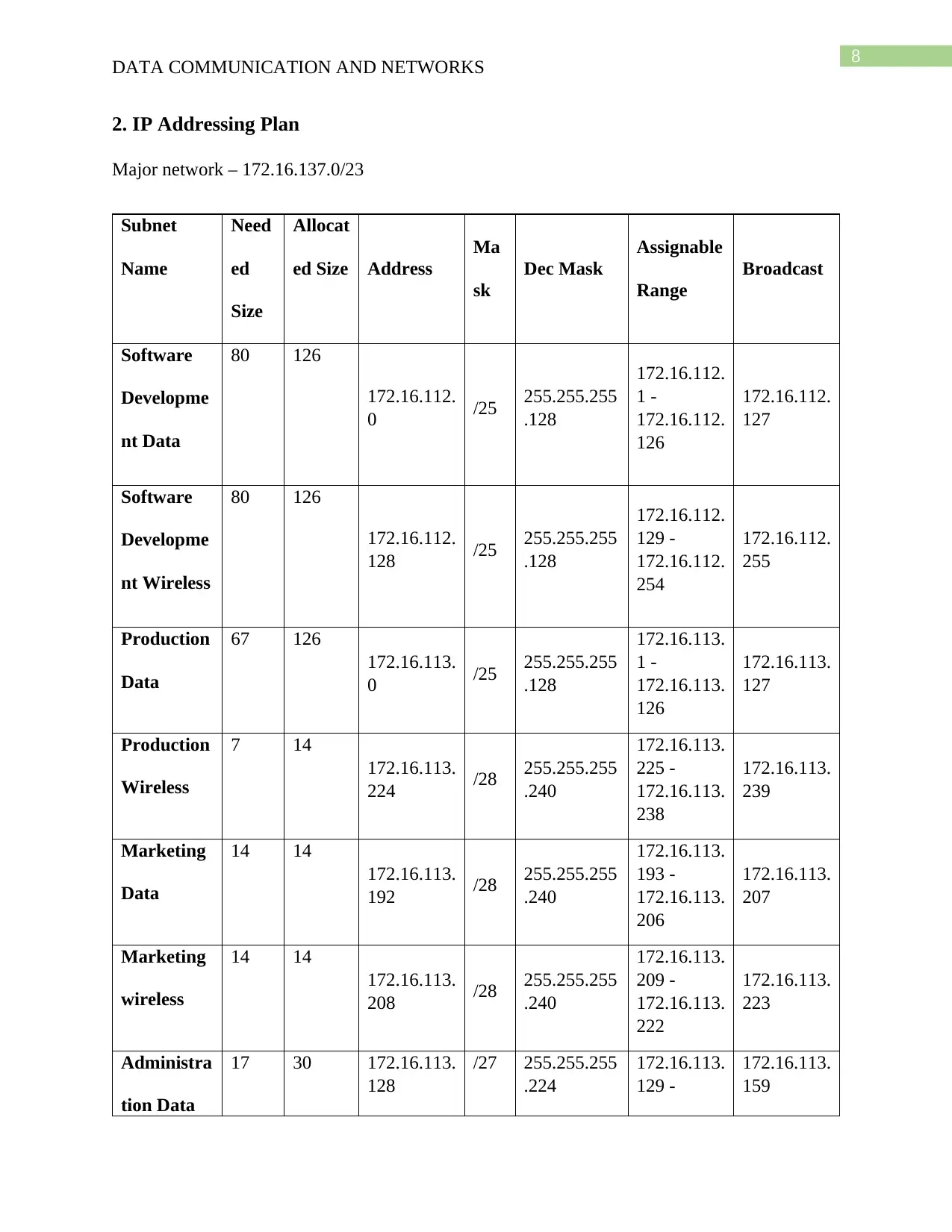
2. IP Addressing Plan
Major network – 172.16.137.0/23
Subnet
Name
Need
ed
Size
Allocat
ed Size Address
Ma
sk
Dec Mask
Assignable
Range
Broadcast
Software
Developme
nt Data
80 126
172.16.112.
0 /25 255.255.255
.128
172.16.112.
1 -
172.16.112.
126
172.16.112.
127
Software
Developme
nt Wireless
80 126
172.16.112.
128 /25 255.255.255
.128
172.16.112.
129 -
172.16.112.
254
172.16.112.
255
Production
Data
67 126
172.16.113.
0 /25 255.255.255
.128
172.16.113.
1 -
172.16.113.
126
172.16.113.
127
Production
Wireless
7 14
172.16.113.
224 /28 255.255.255
.240
172.16.113.
225 -
172.16.113.
238
172.16.113.
239
Marketing
Data
14 14
172.16.113.
192 /28 255.255.255
.240
172.16.113.
193 -
172.16.113.
206
172.16.113.
207
Marketing
wireless
14 14
172.16.113.
208 /28 255.255.255
.240
172.16.113.
209 -
172.16.113.
222
172.16.113.
223
Administra
tion Data
17 30 172.16.113.
128
/27 255.255.255
.224
172.16.113.
129 -
172.16.113.
159
DATA COMMUNICATION AND NETWORKS
2. IP Addressing Plan
Major network – 172.16.137.0/23
Subnet
Name
Need
ed
Size
Allocat
ed Size Address
Ma
sk
Dec Mask
Assignable
Range
Broadcast
Software
Developme
nt Data
80 126
172.16.112.
0 /25 255.255.255
.128
172.16.112.
1 -
172.16.112.
126
172.16.112.
127
Software
Developme
nt Wireless
80 126
172.16.112.
128 /25 255.255.255
.128
172.16.112.
129 -
172.16.112.
254
172.16.112.
255
Production
Data
67 126
172.16.113.
0 /25 255.255.255
.128
172.16.113.
1 -
172.16.113.
126
172.16.113.
127
Production
Wireless
7 14
172.16.113.
224 /28 255.255.255
.240
172.16.113.
225 -
172.16.113.
238
172.16.113.
239
Marketing
Data
14 14
172.16.113.
192 /28 255.255.255
.240
172.16.113.
193 -
172.16.113.
206
172.16.113.
207
Marketing
wireless
14 14
172.16.113.
208 /28 255.255.255
.240
172.16.113.
209 -
172.16.113.
222
172.16.113.
223
Administra
tion Data
17 30 172.16.113.
128
/27 255.255.255
.224
172.16.113.
129 -
172.16.113.
159
⊘ This is a preview!⊘
Do you want full access?
Subscribe today to unlock all pages.
Trusted by 1+ million students worldwide
9
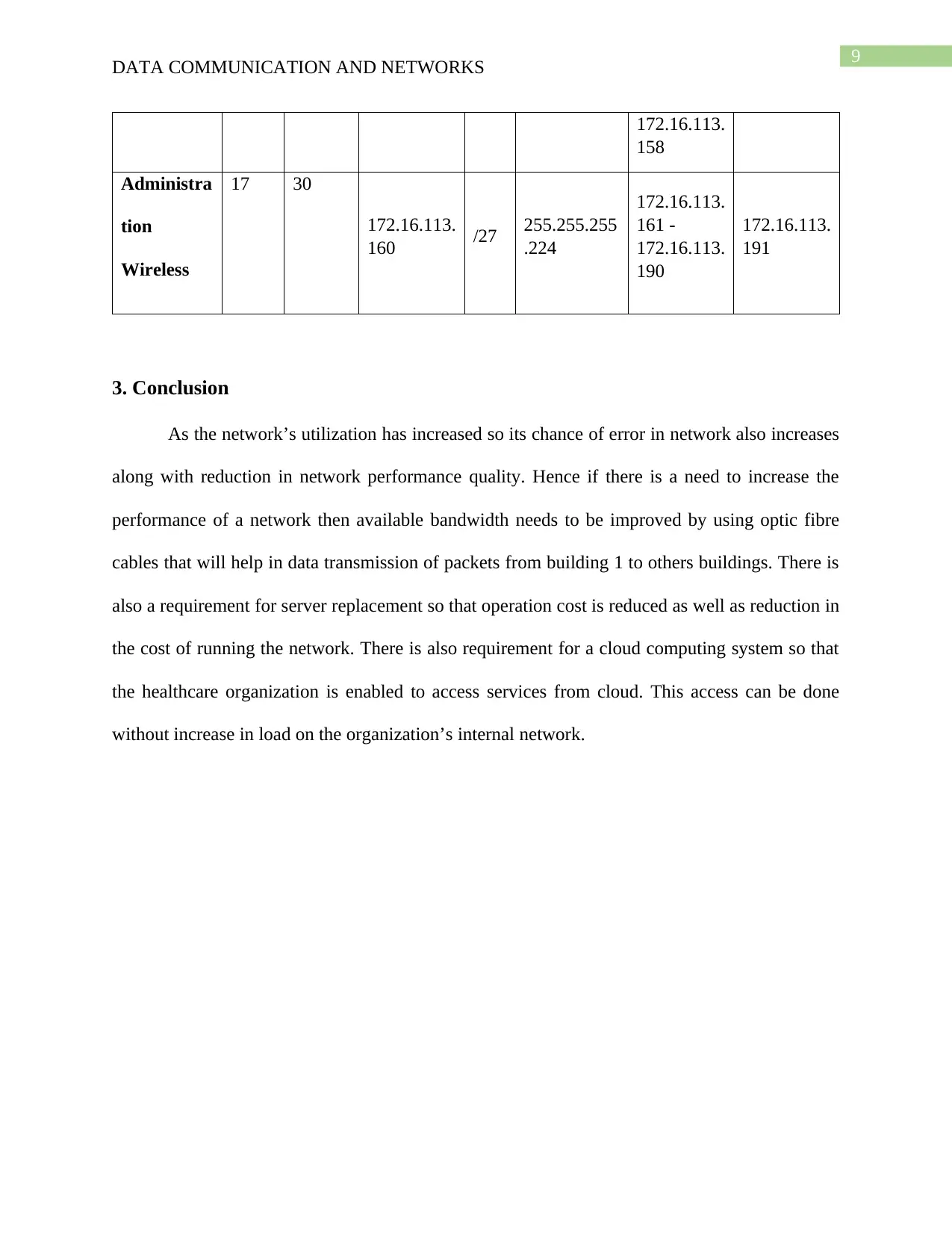
DATA COMMUNICATION AND NETWORKS
172.16.113.
158
Administra
tion
Wireless
17 30
172.16.113.
160 /27 255.255.255
.224
172.16.113.
161 -
172.16.113.
190
172.16.113.
191
3. Conclusion
As the network’s utilization has increased so its chance of error in network also increases
along with reduction in network performance quality. Hence if there is a need to increase the
performance of a network then available bandwidth needs to be improved by using optic fibre
cables that will help in data transmission of packets from building 1 to others buildings. There is
also a requirement for server replacement so that operation cost is reduced as well as reduction in
the cost of running the network. There is also requirement for a cloud computing system so that
the healthcare organization is enabled to access services from cloud. This access can be done
without increase in load on the organization’s internal network.
Paraphrase This Document
Need a fresh take? Get an instant paraphrase of this document with our AI Paraphraser
10
DATA COMMUNICATION AND NETWORKS
References
Bouk, S. H., Ahmed, S. H., Kim, D., & Song, H. (2017). Named-data-networking-based ITS for
smart cities. IEEE Communications Magazine, 55(1), 105-111.
Cunha, F., Villas, L., Boukerche, A., Maia, G., Viana, A., Mini, R. A., & Loureiro, A. A. (2016).
Data communication in VANETs: Protocols, applications and challenges. Ad Hoc
Networks, 44, 90-103.
Moiseenko, I., Wang, L., & Zhang, L. (2015, September). Consumer/producer communication
with application level framing in named data networking. In Proceedings of the 2nd
ACM Conference on Information-Centric Networking (pp. 99-108). ACM.
Saxena, D., Raychoudhury, V., Suri, N., Becker, C., & Cao, J. (2016). Named data networking: a
survey. Computer Science Review, 19, 15-55.
Shang, W., Bannis, A., Liang, T., Wang, Z., Yu, Y., Afanasyev, A., ... & Zhang, L. (2016,
April). Named data networking of things. In 2016 IEEE first international conference on
internet-of-things design and implementation (IoTDI) (pp. 117-128). IEEE.
Shang, W., Yu, Y., Droms, R., & Zhang, L. (2016). Challenges in IoT networking via TCP/IP
architecture. NDN, Technical Report NDN-0038.
11
DATA COMMUNICATION AND NETWORKS
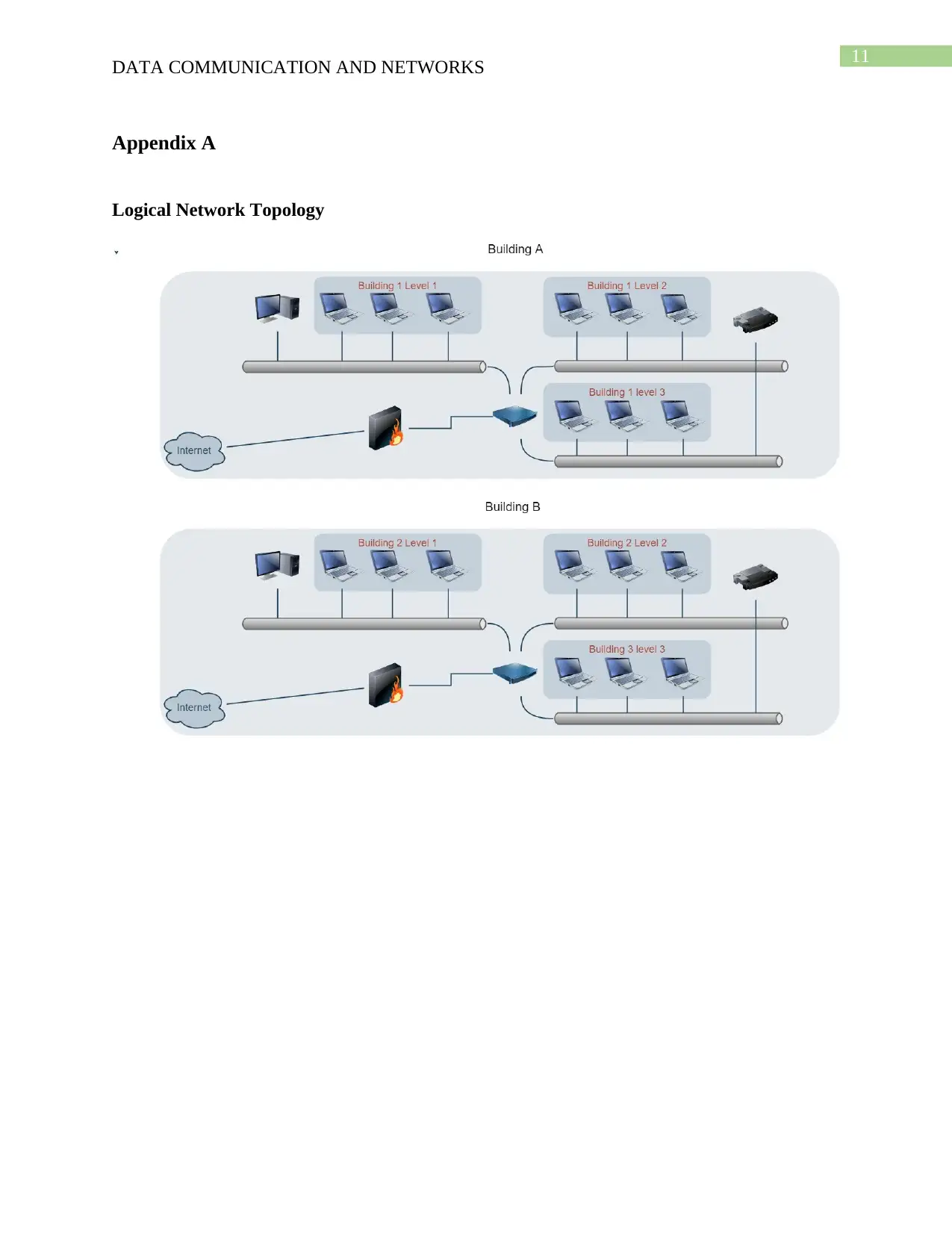
Appendix A
Logical Network Topology
DATA COMMUNICATION AND NETWORKS
Appendix A
Logical Network Topology
⊘ This is a preview!⊘
Do you want full access?
Subscribe today to unlock all pages.
Trusted by 1+ million students worldwide
1 out of 14
Related Documents


Your All-in-One AI-Powered Toolkit for Academic Success.
+13062052269
info@desklib.com
Available 24*7 on WhatsApp / Email
![[object Object]](/_next/static/media/star-bottom.7253800d.svg)
Unlock your academic potential
Copyright © 2020–2026 A2Z Services. All Rights Reserved. Developed and managed by ZUCOL.