Network Topology Report: Design for SUREINSURE's Two-Building Network
VerifiedAdded on 2023/02/01
|10
|1929
|81
Report
AI Summary
This report provides a detailed network topology design for SUREINSURE, an insurance company with two buildings. It begins with an introduction and then delves into the OSI layered architecture, explaining each layer's functionality and its role in network communication. The report compares the OSI model with the TCP/IP model, highlighting their similarities and differences. A diagrammatic comparison of the layers in both models is included. The report then explores the network connectivity options available to SUREINSURE, with discussions on Ethernet and Wi-Fi. The report also presents a diagrammatic representation of the proposed network topology, including VLANs for different departments. The report concludes with a summary of the design and references used.
Table of Contents
Introduction...........................................................................................................................................2
The OSI layered architecture with their respective functionalities.........................................................2
Comparison between the OSI protocol suite with the TCP/IP protocol suite.........................................5
Diagrammatic comparison of the layers in OSI and the TCIP/IP..........................................................6
Network connectivity in the sureinsure company is made possible with the use of the various types of
media.....................................................................................................................................................7
Diagrammatic representation of the network topology for the 2 buildings............................................8
Summary...............................................................................................................................................8
References.............................................................................................................................................9
1
Paraphrase This Document
Need a fresh take? Get an instant paraphrase of this document with our AI Paraphraser
Introduction
SUREINSURE is an organization that has two operational buildings serving as an insurance
company. The organization requires a strong network connection to be implemented in order for the
organization activities to be performed as required. The two buildings are 35 feet away from each
other. It also has eight departments which include offering services to the customers and handling
policy-oriented challenges, the claim department, administration, and contacting the department. Both
wired and wireless networks are required in the company to carry out daily operations. This report
proposes a network topology that employs the standard measures of the network and fulfils the
requirements of the company.
The OSI layered architecture with their respective functionalities
The framework that serves communication between different items within a similar network is the
OSI layered architecture model. The architecture is divided into seven layers with logical
development [1].
The lower part of the architecture mainly deals with data and routing throughout the designated
network as the upper section handles collecting inquiries, responses, presentation, and network
protocols. During the 1970s when PC organizing was developing there were two tasks that were
begun with intention to unite a typical standard for design of systems administration framework. The
first was overseen by global association for benchmarks and the second one was overseen by
worldwide transmit and phone consultative board. In 1983 they were consolidated together to frame
Open System interconnection Reference Model, the OSI model and was distributed in 1984 as a
recognized standard
The OSI is made up of a couple of layers that are seven in number which includes
The physical layer
The data link layer
The network layer
The transport session layer
The presentation layer
And lastly the application layer [2].
2
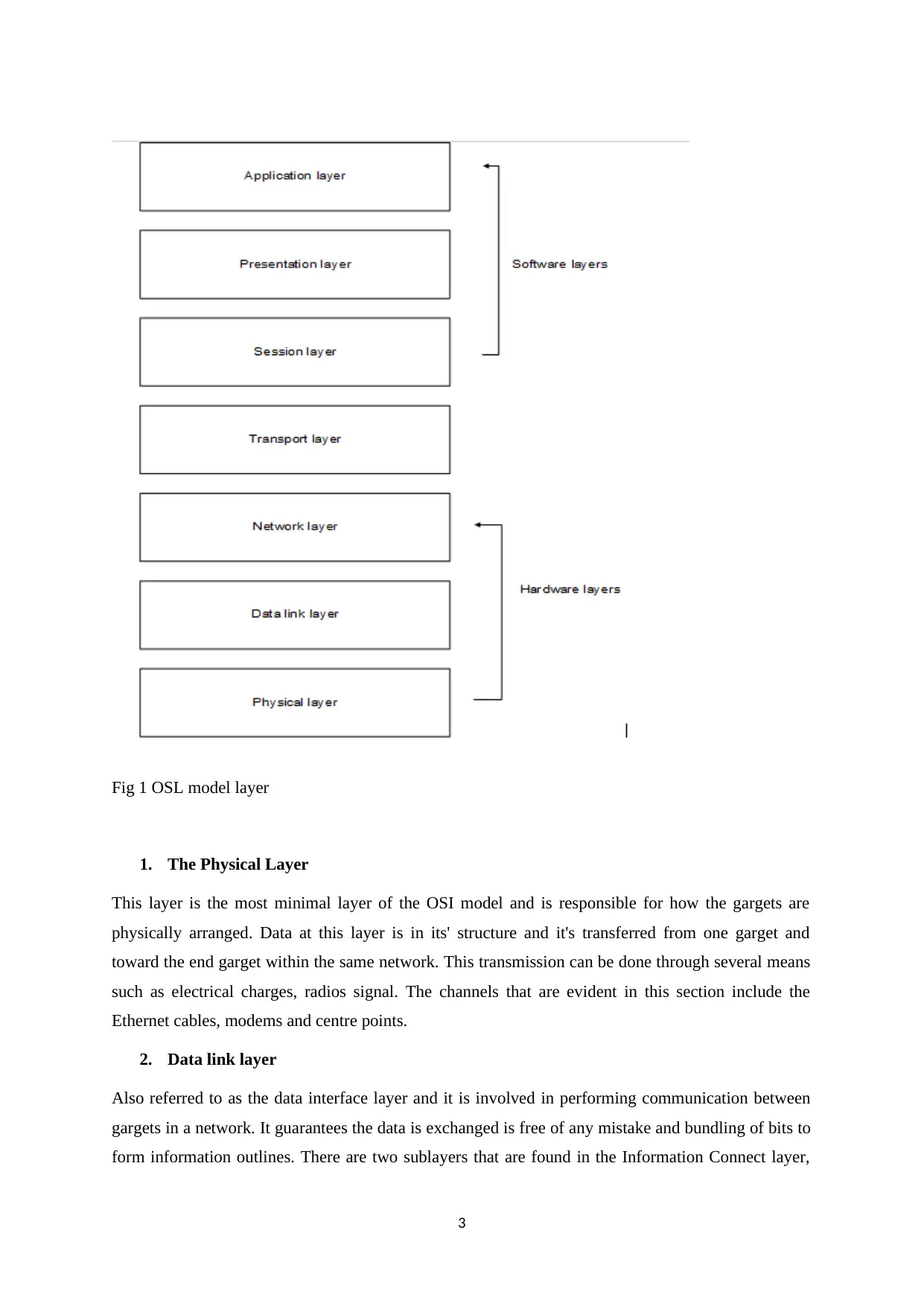
Fig 1 OSL model layer
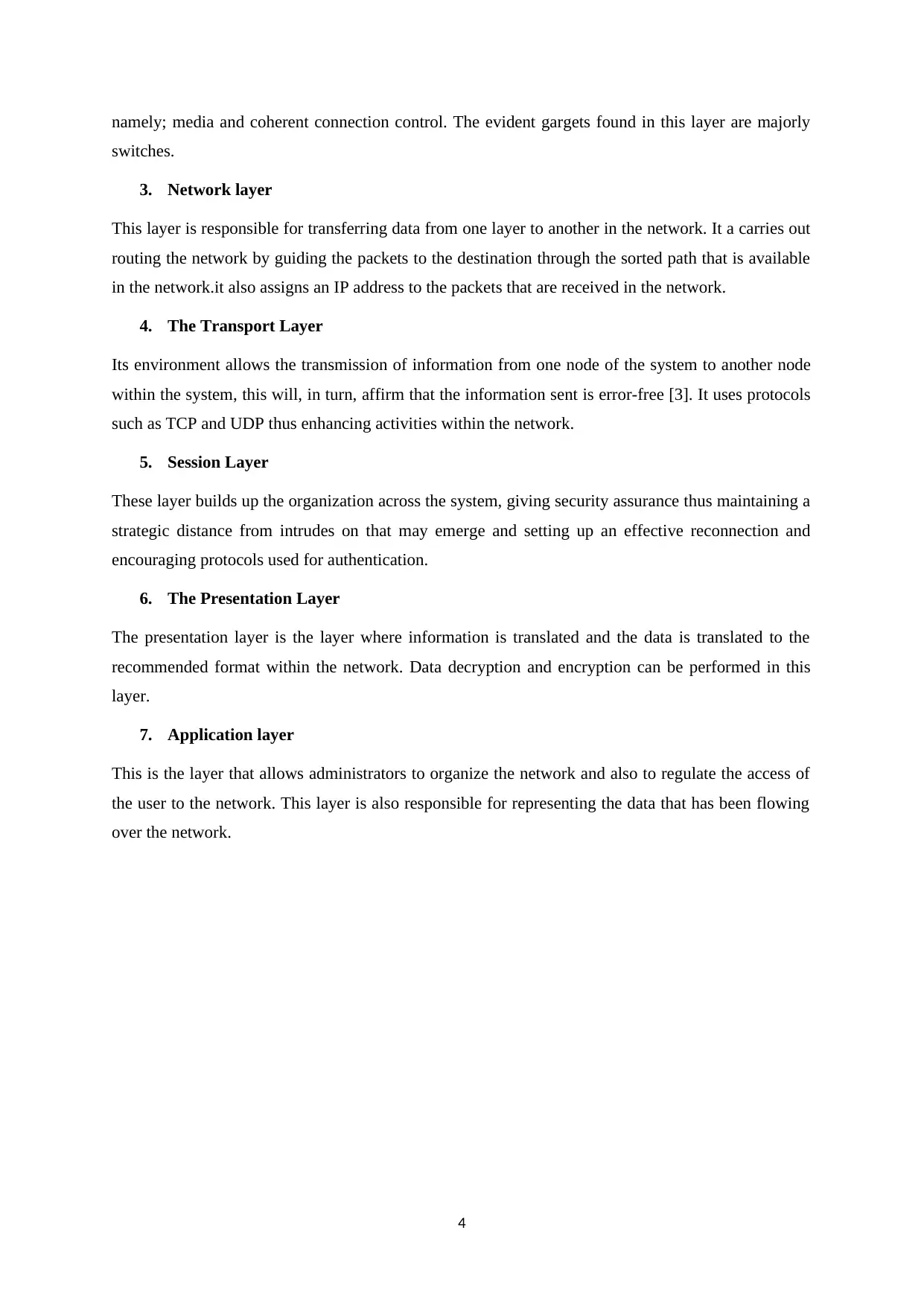
1. The Physical Layer
This layer is the most minimal layer of the OSI model and is responsible for how the gargets are
physically arranged. Data at this layer is in its' structure and it's transferred from one garget and
toward the end garget within the same network. This transmission can be done through several means
such as electrical charges, radios signal. The channels that are evident in this section include the
Ethernet cables, modems and centre points.
2. Data link layer
Also referred to as the data interface layer and it is involved in performing communication between
gargets in a network. It guarantees the data is exchanged is free of any mistake and bundling of bits to
form information outlines. There are two sublayers that are found in the Information Connect layer,
3
⊘ This is a preview!⊘
Do you want full access?
Subscribe today to unlock all pages.
Trusted by 1+ million students worldwide
namely; media and coherent connection control. The evident gargets found in this layer are majorly
switches.
3. Network layer
This layer is responsible for transferring data from one layer to another in the network. It a carries out
routing the network by guiding the packets to the destination through the sorted path that is available
in the network.it also assigns an IP address to the packets that are received in the network.
4. The Transport Layer
Its environment allows the transmission of information from one node of the system to another node
within the system, this will, in turn, affirm that the information sent is error-free [3]. It uses protocols
such as TCP and UDP thus enhancing activities within the network.
5. Session Layer
These layer builds up the organization across the system, giving security assurance thus maintaining a
strategic distance from intrudes on that may emerge and setting up an effective reconnection and
encouraging protocols used for authentication.
6. The Presentation Layer
The presentation layer is the layer where information is translated and the data is translated to the
recommended format within the network. Data decryption and encryption can be performed in this
layer.
7. Application layer
This is the layer that allows administrators to organize the network and also to regulate the access of
the user to the network. This layer is also responsible for representing the data that has been flowing
over the network.
4
Paraphrase This Document
Need a fresh take? Get an instant paraphrase of this document with our AI Paraphraser
Comparison between the OSI protocol suite with the TCP/IP protocol suite
Similarities between these protocols [4]
i. They both have a layered architecture.
ii. They perform similar tasks.
iii. They are both stacks.
iv. Both the network models being reference models
They have the following differences
i. There are seven layers present in the OSI layer while TCP is made up of 4 layers.
ii. The TCP only offers wireless connection while the OSL layer offers both wireless and
wire services.
iii. The presentation layers in the OSI model is separated while in TCP it’s not.
iv. OSL is protocol depended while TCP is not protocol dependent.
v. The OSI network model is a framework that allows movement of information or
command between the client and the system while on the other hand, the TCP/IP model is
a framework allows the firm of the user across the entire system.
5
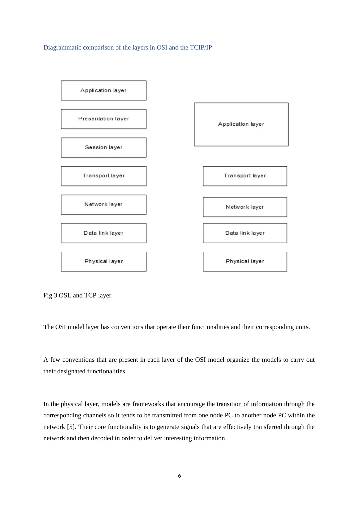
Diagrammatic comparison of the layers in OSI and the TCIP/IP
Fig 3 OSL and TCP layer
The OSI model layer has conventions that operate their functionalities and their corresponding units.
A few conventions that are present in each layer of the OSI model organize the models to carry out
their designated functionalities.
In the physical layer, models are frameworks that encourage the transition of information through the
corresponding channels so it tends to be transmitted from one node PC to another node PC within the
network [5]. Their core functionality is to generate signals that are effectively transferred through the
network and then decoded in order to deliver interesting information.
6
⊘ This is a preview!⊘
Do you want full access?
Subscribe today to unlock all pages.
Trusted by 1+ million students worldwide
The Data link layer. ARP (operates with resolution protocol) which is a protocol that serves in
communicating and also determines the addresses found in the Link Layer, in relation to a specific
internet Layer Address.
Network layer. ICMP (internet control message protocol)
Transport layer. The Data Congestion Control Protocol, also DCCP, is a framework executes setups
of association, controls the clogs and also highlights the arrangement. The IETF (Internet engineering
task force), is the body charged with its standardization.
The session layer; at this layer authentication of the user is performed to approve the client’s details
remotely with the use of the PAP (password authentication protocol) protocol. The International
Telecommunication Union (ITU) is the body responsible for its standardization.
The presentation layer uses Secure Socket Layer which is a framework that offers effective security
across the system. The body that is responsible for its standardization is the International Standard
Organization (ISO).
At the application layer, the Domain Name System is a suitable framework that merges different data
with their domain name with its partaking substance it is doled out to. The body responsible for its
standardization is the International Standard Organization (ISO).
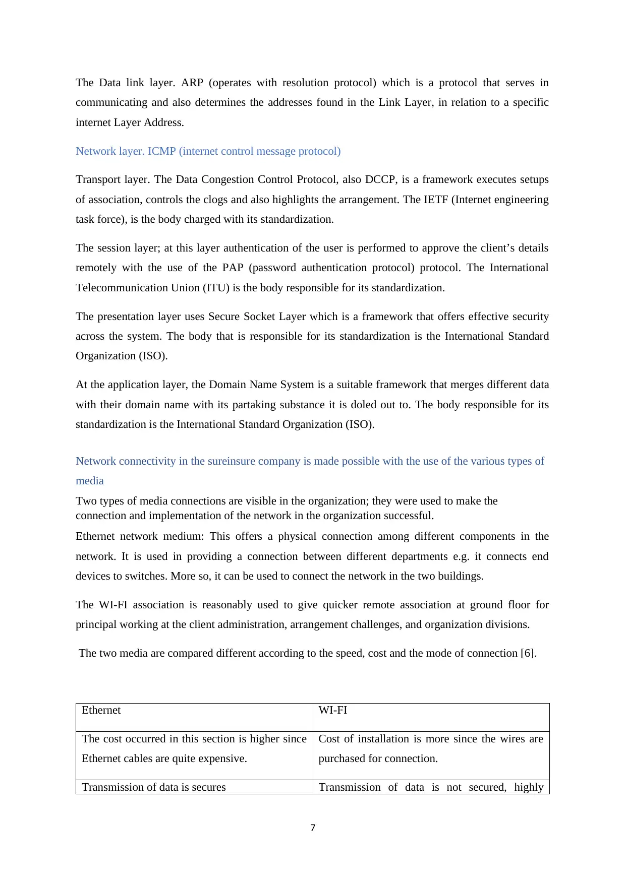
Network connectivity in the sureinsure company is made possible with the use of the various types of
media
Two types of media connections are visible in the organization; they were used to make the
connection and implementation of the network in the organization successful.
Ethernet network medium: This offers a physical connection among different components in the
network. It is used in providing a connection between different departments e.g. it connects end
devices to switches. More so, it can be used to connect the network in the two buildings.
The WI-FI association is reasonably used to give quicker remote association at ground floor for
principal working at the client administration, arrangement challenges, and organization divisions.
The two media are compared different according to the speed, cost and the mode of connection [6].
Ethernet WI-FI
The cost occurred in this section is higher since
Ethernet cables are quite expensive.
Cost of installation is more since the wires are
purchased for connection.
Transmission of data is secures Transmission of data is not secured, highly
7
communicating and also determines the addresses found in the Link Layer, in relation to a specific
internet Layer Address.
Network layer. ICMP (internet control message protocol)
Transport layer. The Data Congestion Control Protocol, also DCCP, is a framework executes setups
of association, controls the clogs and also highlights the arrangement. The IETF (Internet engineering
task force), is the body charged with its standardization.
The session layer; at this layer authentication of the user is performed to approve the client’s details
remotely with the use of the PAP (password authentication protocol) protocol. The International
Telecommunication Union (ITU) is the body responsible for its standardization.
The presentation layer uses Secure Socket Layer which is a framework that offers effective security
across the system. The body that is responsible for its standardization is the International Standard
Organization (ISO).
At the application layer, the Domain Name System is a suitable framework that merges different data
with their domain name with its partaking substance it is doled out to. The body responsible for its
standardization is the International Standard Organization (ISO).
Network connectivity in the sureinsure company is made possible with the use of the various types of
media
Two types of media connections are visible in the organization; they were used to make the
connection and implementation of the network in the organization successful.
Ethernet network medium: This offers a physical connection among different components in the
network. It is used in providing a connection between different departments e.g. it connects end
devices to switches. More so, it can be used to connect the network in the two buildings.
The WI-FI association is reasonably used to give quicker remote association at ground floor for
principal working at the client administration, arrangement challenges, and organization divisions.
The two media are compared different according to the speed, cost and the mode of connection [6].
Ethernet WI-FI
The cost occurred in this section is higher since
Ethernet cables are quite expensive.
Cost of installation is more since the wires are
purchased for connection.
Transmission of data is secures Transmission of data is not secured, highly
7
Paraphrase This Document
Need a fresh take? Get an instant paraphrase of this document with our AI Paraphraser
vulnerable
Transfers data at high speed. Data transmission is a bit slower.
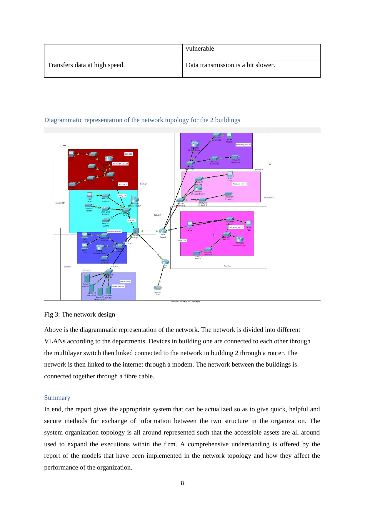
Diagrammatic representation of the network topology for the 2 buildings
Fig 3: The network design
Above is the diagrammatic representation of the network. The network is divided into different
VLANs according to the departments. Devices in building one are connected to each other through
the multilayer switch then linked connected to the network in building 2 through a router. The
network is then linked to the internet through a modem. The network between the buildings is
connected together through a fibre cable.
Summary
In end, the report gives the appropriate system that can be actualized so as to give quick, helpful and
secure methods for exchange of information between the two structure in the organization. The
system organization topology is all around represented such that the accessible assets are all around
used to expand the executions within the firm. A comprehensive understanding is offered by the
report of the models that have been implemented in the network topology and how they affect the
performance of the organization.
8
Transfers data at high speed. Data transmission is a bit slower.
Diagrammatic representation of the network topology for the 2 buildings
Fig 3: The network design
Above is the diagrammatic representation of the network. The network is divided into different
VLANs according to the departments. Devices in building one are connected to each other through
the multilayer switch then linked connected to the network in building 2 through a router. The
network is then linked to the internet through a modem. The network between the buildings is
connected together through a fibre cable.
Summary
In end, the report gives the appropriate system that can be actualized so as to give quick, helpful and
secure methods for exchange of information between the two structure in the organization. The
system organization topology is all around represented such that the accessible assets are all around
used to expand the executions within the firm. A comprehensive understanding is offered by the
report of the models that have been implemented in the network topology and how they affect the
performance of the organization.
8

9
⊘ This is a preview!⊘
Do you want full access?
Subscribe today to unlock all pages.
Trusted by 1+ million students worldwide
References
[1]E. Bulur, "A simple transformation for converting CW-OSL curves to LM-OSL curves", Radiation
Measurements, vol. 32, no. 2, pp. 141-145, 2010. Available: 10.1016/s1350-4487(99)00247-4.
[2]D. Wetteroth, OSI reference model for telecommunications. New York: McGraw-Hill, 2012.
[3] Bernstein, G.M., Chapman, A., Edholm, P., Gullicksen, J.T. and Gullicksen, K., Nortel Networks
Ltd,. Method and apparatus for accelerating OSI layer 3 routers. U.S. Patent 6,157,64, 2010.
[4]A. Kumar and S. Karthikeyan, "Security Model for TCP/IP Protocol Suite", Journal of Advances
in Information Technology, vol. 2, no. 2, 2011. Available: 10.4304/jait.2.2.87-91.
[5]A. Kumar and S. Karthikeyan, "Security Model for TCP/IP Protocol Suite", Journal of Advances
in Information Technology, vol. 2, no. 2, 2011. Available: 10.4304/jait.2.2.87-91.
[6] Ketheeswaren, S., Rosilinmary, S. and Visvanath, B.,. Models of Transmission Media for a
Library Network: A Comparative Study, 2011.
10
1 out of 10
Related Documents


Your All-in-One AI-Powered Toolkit for Academic Success.
+13062052269
info@desklib.com
Available 24*7 on WhatsApp / Email
![[object Object]](/_next/static/media/star-bottom.7253800d.svg)
Unlock your academic potential
Copyright © 2020–2026 A2Z Services. All Rights Reserved. Developed and managed by ZUCOL.