Network Design and Troubleshooting Report: Speedfix.co.uk Network
VerifiedAdded on 2022/08/19
|21
|3941
|11
Report
AI Summary
This report details the network design and troubleshooting for Speedfix.co.uk, a small organization with four departments and specific network requirements. The design incorporates VLANs for department isolation, DHCP for dynamic IP assignment, and access control lists. The report analyzes network components such as routers, switches, and wireless access points, and includes a detailed network diagram created using Cisco Packet Tracer. The implementation focuses on establishing secure communication between departments and servers, while also integrating IoT devices. The report covers the analysis of the network model, the implementation details, and the testing and documentation of the network. The report also includes discussion on the technologies used, such as Ethernet, IP addressing, and the default gateway. The network design ensures that departments can access the servers but not each other, fulfilling the organization's key business criteria.

Running head: NETWORK DESIGN AND TROUBLESHOOTING
Network Design and Troubleshooting
Name of the Student
Name of the University
Author Note
Network Design and Troubleshooting
Name of the Student
Name of the University
Author Note
Paraphrase This Document
Need a fresh take? Get an instant paraphrase of this document with our AI Paraphraser
1NETWORK DESIGN AND TROUBLESHOOTING
Table of Contents
Introduction:....................................................................................................................................2
Understanding of the Network Model:............................................................................................3
Analysis of the Network:.................................................................................................................5
Router:.........................................................................................................................................5
Switches:......................................................................................................................................6
Wireless Access Points:...............................................................................................................6
Computer Systems:......................................................................................................................6
Implementation of the Network:......................................................................................................7
Network Diagram:.......................................................................................................................7
DHCP Service:.............................................................................................................................8
VLAN:.........................................................................................................................................8
Trunking:.....................................................................................................................................9
Access Control:............................................................................................................................9
Testing and Documentation:............................................................................................................9
Conclusion:....................................................................................................................................16
References:....................................................................................................................................18
2NETWORK DESIGN AND TROUBLESHOOTING
Introduction:
Speedfix.co.uk is a small organization that is currently looking to implement a network
infrastructure for its organizational purposes. This organization is structured into four
departments, which are the Finance/HR department, Sales department, Engineers department,
and Admins department. There are a total of four servers in the organization which are important
for performing daily operations of the organization. These four servers are the email server, web
server, DNS server, and common file server. These servers are shared across all the users, where
the users are free to access them. There is an important requirement for this network system,
which is that each department must not have any access to other departments. Each department
will only be able to access the servers of the organization. In the finance department, there are 10
computers and a printer. The sales department have 37 computer and printer. Engineers
department have 19 computer and printer. The admin department does have 4 computers and a
printer. Apart from these individual departments, there are wireless access points present, which
are also able to access any of the servers, but the wireless access points will be unable to access
any of the individual departments of the organization. In this network, some IoT devices will
also be included for monitoring the temperature and the server room door. Currently,
Speedfix.co.uk is intended to use its private network IP address, which is 192.168.168.0/24, and
that will be used for wired communication. For the wireless connection, the organization is
intended to use the 10.10.10.0/24 network.
For the configuration of this network, some important concepts from networking have
been used, including the VLAN and access control list (Cao et al. 2020). These concepts have
been used for preparing the overall network design as per the requirements. Also, the DHCP
⊘ This is a preview!⊘
Do you want full access?
Subscribe today to unlock all pages.
Trusted by 1+ million students worldwide
3NETWORK DESIGN AND TROUBLESHOOTING
protocol has been used in this network configuration so that all the IP addresses can be assigned
dynamically. Also, some IoT devices have been included in the network configuration.
Understanding of the Network Model:
In the current network model, there are a total of four departments, which are the
Finance/HR department, Sales department, Admin department, and the Engineer department.
These four departments are the main operations department of Speedfix.co.uk, and for this
reason, it has been involved in the overall network design. The finance/HR department has ten
computers. The Sales department has 37 computer systems, 19 computers in the Engineering
department and four computers in the Admin department. To provide important functionality to
these computer systems, there are four important servers, which are the DNS server, Email
server, Web server, and the File Server. Each of the servers are important for overall
functionality of the organization. As per the network requirement of the organization, each of the
four departments is able to access all the servers individually (Tagliacane et al. 2016). Here, all
the computer systems present in each of the departments of the Speedfix.co.uk are able to
communicate with the servers, but inter-department communication is prohibited in this network
design, which is an important business criterion for Speedfix.co.uk.
Thus, according to the business criteria of the organization, the proper network needs to
be developed. In this context, before the development of the actual network, it is important to
check the feasibility of the project. Budget is one of the important criteria for testing the
feasibility of a project or a system (Mesly 2017), but it has been excluded here from the
feasibility testing. The main criteria of the testing are whether the current network architecture
can be implemented in the organization or not. Thus, a simulation needs to be performed of the
actual system so that it can be ensured that the actual system will be working fine in the
Paraphrase This Document
Need a fresh take? Get an instant paraphrase of this document with our AI Paraphraser
4NETWORK DESIGN AND TROUBLESHOOTING
organization (Rosewell et al. 2018). In this context, simulation has been performed using the
Cisco Packet Tracer software. Here, a rough implementation of the actual system has been done
within the logical surface of the software (Muniasamy, Ejlani and Anadhavalli 2019), and
following that, each of the network components have been configured accordingly so that proper
connection can be established among the networking components.
For developing the actual network of the organization, proper network topology needs to
be developed. The network topology is considered as the arrangement of elements within a
communication network (Segarra et al. 2017). The network topology is mainly used for
describing the arrangements of various telecommunication networks. This telecommunication
network can include control and command radio networks, computer networks, and industrial
field-busses network. The current network topology is a computer network. There are several
network topologies that can be used for designing a network. These topologies are the star
topology, bus topology, ring topology, hybrid topology, mesh topology, and the tree topology
(Nedić, Olshevsky, and Rabbat 2018). A specific type of topology is important for designing
some specific types of network systems.
There are several important concepts that are associated with the designing of the present
network. Ethernet is crucial component that play an important role in designing this network
system (Ishak, Leong and Sirajudin 2019). Ethernet is an important protocol for the
configuration of the local area network. Ethernet cables are used for creating a LAN, which has
also been used in the current design of the network. Next, IP addressing and sub-netting is
another important area. To function in a network, each of the computer systems must have a
unique Layer 3 address, which is the IP address (Almohri, Watson and Evans 2019). An IP
address consists of a total of four numbers that are separated by the dots. In several cases, the IP
5NETWORK DESIGN AND TROUBLESHOOTING
address is divided into smaller blocks, and this process is known as the IP sub-netting. Both of
the IP addressing and the sub-netting has been used for configuring the current network. The
default gateway is another important aspect used for network designing purposes. The default
gateway is used for communication among two computer devices (Lemeshko, Yeremenko and
Tariki 2017). The default gateway does not exist in the local area network. The default gateway
presents in the local router of the network topology. The default gateway network is not
essential, but it is important to establish a connection with another network. These are the main
area regarding networking that has been used for developing this network.
Analysis of the Network:
For the development of this network for Speedfix.co.uk different type of network
component has been used. These networking devices include routers, switches, wireless access
points, printers, smartphones, and personal computer systems. For establishing connections
between the devices, two types of cables have been used. These cables are the copper straight-
through wire and copper cross-over wire. The copper straight-through wire is used for
connecting different types of devices where the copper cross-over wire is used for establishing
connection similar types of devices. In the following section, an important component that has
been used is discussed.
Router:
The router is one of the important network components used in the networking purpose.
The router is an important component that is used for routing the traffic between different
subnets. A router functions in layer 3 of the OSI model (List 2020). In a common situation, a
router is mainly used for routing the traffic from LAN connection to a WAN connection. In large
organizations, the router is used for routing the traffic between various IP subnets within a big
⊘ This is a preview!⊘
Do you want full access?
Subscribe today to unlock all pages.
Trusted by 1+ million students worldwide
6NETWORK DESIGN AND TROUBLESHOOTING
LAN. For the network of Speedfix.co.uk router has been used for routing the traffic among the
IP subnets.
Switches:
Switches are another important network component that has been used for designing the
current network infrastructure for Speedfix.co.uk. The switches executes on OSI model’s layer 2,
and it is used for connecting all the devices on the LAN (Kwon et al. 2017). The switches are
capable of switching the frames depending on the endpoint MAC address for a specific frame.
Switches are available in a variety of sizes, and the users are free to choose depending on their
requirements. In the current network, industry level switches have been used for developing the
connection.
Wireless Access Points:
The wireless access points have also been implemented within this network. In
networking, a wireless access point is a common type of hardware that is mainly used for
allowing the Wi-Fi devices to be connected with a wired network. A common wireless access
point can be a standalone device that will be connected with the router (Li et al. 2019). In the
current network, wireless access points have been used for connecting the wireless mobile
devices with the network of Speedfix.co.uk. This wireless access point will provide the
connectivity to the mobile devices so that they can access the important files from the
organization.
Computer Systems:
Computer systems have also been used for the network designing purpose within the
network of Speedfix.co.uk. The computer systems have been mainly used for performing
Paraphrase This Document
Need a fresh take? Get an instant paraphrase of this document with our AI Paraphraser
7NETWORK DESIGN AND TROUBLESHOOTING
organizational operations and for communication purposes with other devices. The computer
system will be used for accessing important information from the servers. Also, the computer
systems will be used for accessing information from a different computer system within the same
department.
Implementation of the Network:
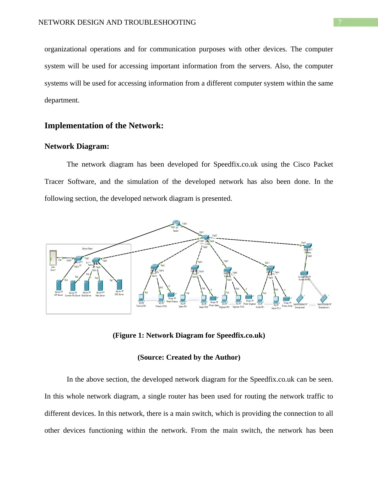
Network Diagram:
The network diagram has been developed for Speedfix.co.uk using the Cisco Packet
Tracer Software, and the simulation of the developed network has also been done. In the
following section, the developed network diagram is presented.
(Figure 1: Network Diagram for Speedfix.co.uk)
(Source: Created by the Author)
In the above section, the developed network diagram for the Speedfix.co.uk can be seen.
In this whole network diagram, a single router has been used for routing the network traffic to
different devices. In this network, there is a main switch, which is providing the connection to all
other devices functioning within the network. From the main switch, the network has been
organizational operations and for communication purposes with other devices. The computer
system will be used for accessing important information from the servers. Also, the computer
systems will be used for accessing information from a different computer system within the same
department.
Implementation of the Network:
Network Diagram:
The network diagram has been developed for Speedfix.co.uk using the Cisco Packet
Tracer Software, and the simulation of the developed network has also been done. In the
following section, the developed network diagram is presented.
(Figure 1: Network Diagram for Speedfix.co.uk)
(Source: Created by the Author)
In the above section, the developed network diagram for the Speedfix.co.uk can be seen.
In this whole network diagram, a single router has been used for routing the network traffic to
different devices. In this network, there is a main switch, which is providing the connection to all
other devices functioning within the network. From the main switch, the network has been
8NETWORK DESIGN AND TROUBLESHOOTING
subdivided into a total of six parts. The first sub-switch is connected with the servers of the
organization. The second sub-switch is for the Finance/HR department. The third sub-switch is
for the Sales department. The fourth sub-switch is connected to the Engineer department. The
fifth sub-switch is connected with the Admin department, and the last sub-switch is used for the
wireless access points to provide connectivity to the wireless devices. For connecting each of the
switches to the router, the subnet interface has been used. Here, a total of six subnets has been
created in the router for connecting each of the sub-switch through the main switch. These
subnets have been created in the FastEthernet Port 0/0 of the main router. All the servers are
connected to the router through the subnet network 192.168.168.0. Similarly, the Finance/HR
department is connected to the subnet network 192.168.2.0. The other departments, which are the
Sales department, Engineer department, Admin department, and the wireless access point, are
connected to subnet network 192.168.3.0, 192.168.4.0, 192.168.5.0 and 10.10.10.0 respectively.
The IoT devices are connected with the router through the FastEthernet port, and an intermediate
switch has also been used for the connection purpose where the used IP is 192.168.100.1.
DHCP Service:
The DHCP service has been configured in the router for automatic assigning of the IP
addresses to all the networking devices dynamically. The DHCP is important in this network as it
establishes the communication between the devices among the networks (Yaibuates,
Chaisricharoen and Rai 2018).
VLAN:
VLANs have also been used in this network configuration for differentiating each of the
departments in the organization. A VLAN or the virtual LAN is any domain of broadcast that is
isolated and partitioned within a computer network at the data link layer (Nguyen and Kim
⊘ This is a preview!⊘
Do you want full access?
Subscribe today to unlock all pages.
Trusted by 1+ million students worldwide
9NETWORK DESIGN AND TROUBLESHOOTING
2016). By using the VLAN in this network, logical groups of devices have been created within
the same broadcasting domain. VLANs are configured through the switches. In this network,
each of the departments has been configured through a VLAN for creating a separate logical
network in the main network. VLANs are important for this network so that inter-department
communication can be restricted, which is one of the important requirements of Speedfix.co.uk.
Trunking:
Trunking has also been used using the switch for this network. The trunking is the
method for providing network access to various clients. The trunking is achieved by sharing a set
of frequencies instead of providing the frequencies in a sequential way (Dong and Gong 2019).
Regarding the trunking process, VTP or the VLAN Trunking Protocol has been used for this
network. In the VTP configuration, VTP carries the information of VLAN to all the switches
within a VTP domain.
Access Control:
Also, the configuration of this network includes access control. The network access
control is an approach used in computer security for implementing an authentication limitation
(Tourani et al. 2017). The access control list has been used in this network for restricting the
communication between all the four departments of the Speedfix.co.uk. The access control list
ensures that all the departments will only be able to access the servers of the organization.
Testing and Documentation:
Speedfix.co.uk has implemented this network so that each of the four departments of the
organization can communicate with the servers of the organization so that important documents
can be accessed. Though all the departments are communicating with server, each of the
Paraphrase This Document
Need a fresh take? Get an instant paraphrase of this document with our AI Paraphraser
10NETWORK DESIGN AND TROUBLESHOOTING
departments is isolated from each other, which is the network requirement of Speedfix.co.uk.
Also, the wireless network is only able to access the servers and will not be able to access any
department of the organization. In the following section, testing of the network is demonstrated.
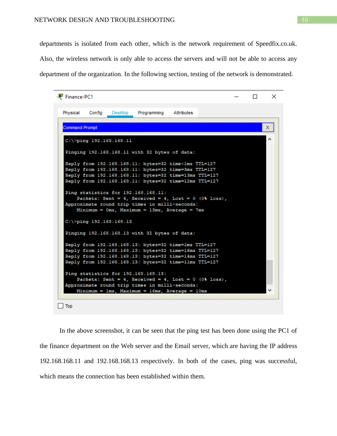
In the above screenshot, it can be seen that the ping test has been done using the PC1 of
the finance department on the Web server and the Email server, which are having the IP address
192.168.168.11 and 192.168.168.13 respectively. In both of the cases, ping was successful,
which means the connection has been established within them.
departments is isolated from each other, which is the network requirement of Speedfix.co.uk.
Also, the wireless network is only able to access the servers and will not be able to access any
department of the organization. In the following section, testing of the network is demonstrated.
In the above screenshot, it can be seen that the ping test has been done using the PC1 of
the finance department on the Web server and the Email server, which are having the IP address
192.168.168.11 and 192.168.168.13 respectively. In both of the cases, ping was successful,
which means the connection has been established within them.
11NETWORK DESIGN AND TROUBLESHOOTING
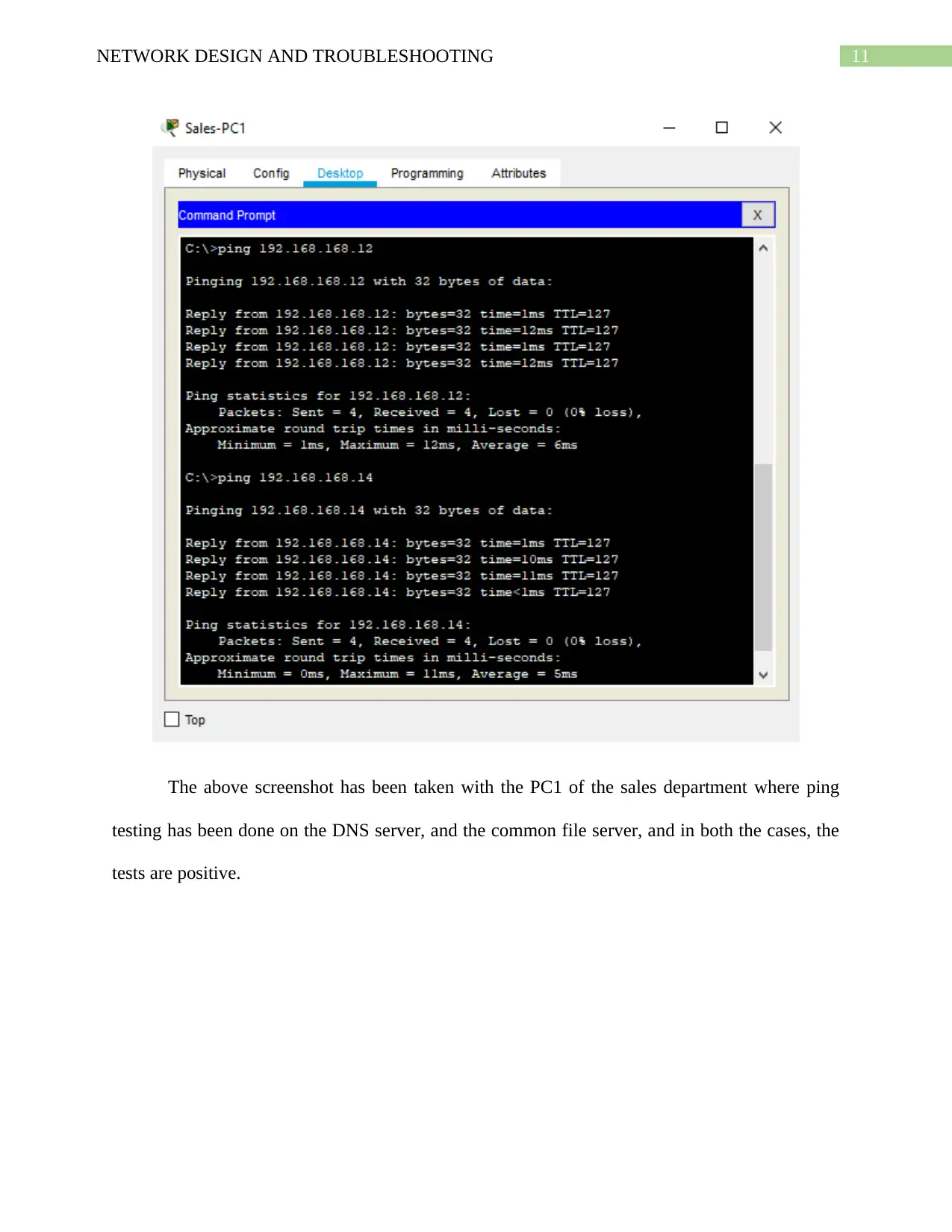
The above screenshot has been taken with the PC1 of the sales department where ping
testing has been done on the DNS server, and the common file server, and in both the cases, the
tests are positive.
The above screenshot has been taken with the PC1 of the sales department where ping
testing has been done on the DNS server, and the common file server, and in both the cases, the
tests are positive.
⊘ This is a preview!⊘
Do you want full access?
Subscribe today to unlock all pages.
Trusted by 1+ million students worldwide
1 out of 21
Related Documents


Your All-in-One AI-Powered Toolkit for Academic Success.
+13062052269
info@desklib.com
Available 24*7 on WhatsApp / Email
![[object Object]](/_next/static/media/star-bottom.7253800d.svg)
Unlock your academic potential
Copyright © 2020–2026 A2Z Services. All Rights Reserved. Developed and managed by ZUCOL.