College of Science: Network Design and Validation Project
VerifiedAdded on  2022/09/15
|14
|2503
|16
Project
AI Summary
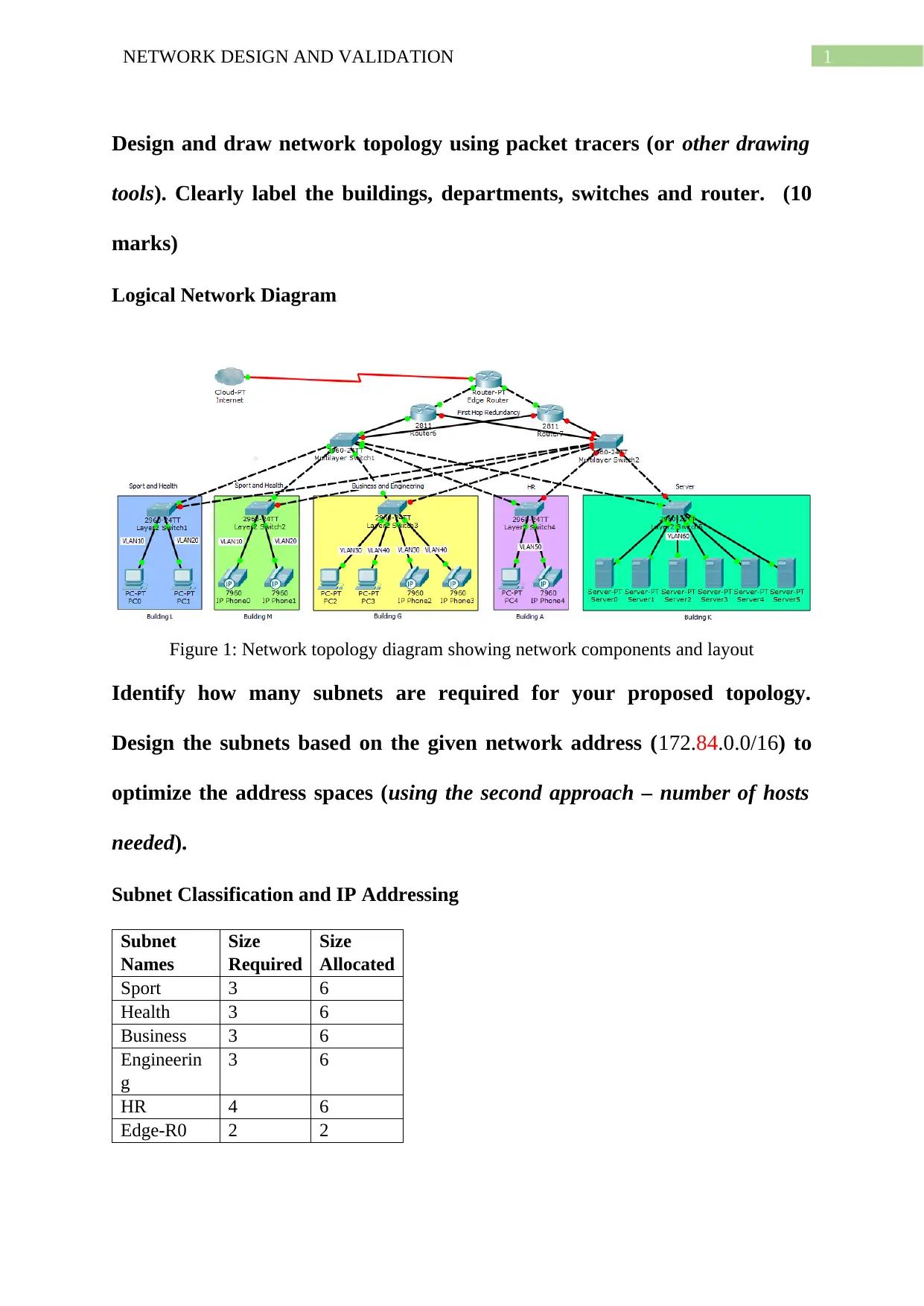
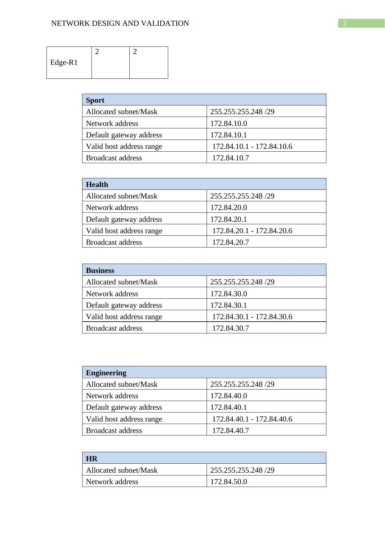
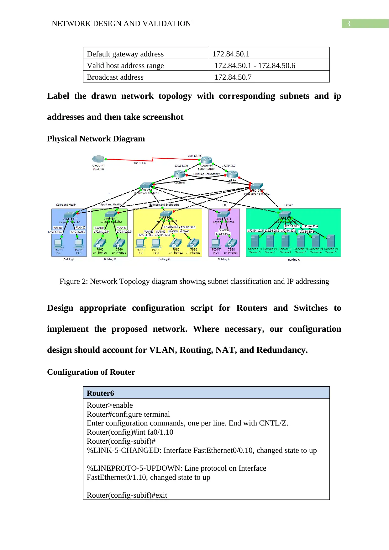
This document presents a comprehensive solution to a network design and validation assignment. The project begins with the design of a network topology using Packet Tracer, clearly labeling buildings, departments, and network devices. The solution then addresses subnetting requirements based on the provided network address, optimizing address spaces for various departments (Sport, Health, Business, Engineering, and HR) and edge routers. Detailed subnet classifications, IP addressing schemes, and logical and physical network diagrams are provided. Configuration scripts for routers and multilayer switches are designed to implement VLANs, routing, and DHCP. The solution includes configuration of router interfaces with sub-interfaces, VLAN configuration on switches, and DHCP pool configurations. The assignment concludes with network performance verification, including ping tests to validate inter-VLAN routing and network functionality, and screenshots demonstrating successful packet transmissions between different network segments, servers, and the router. A bibliography of relevant research papers is also included.

Running head: NETWORK DESIGN AND VALIDATION
Network Design and Validation
Name of the Student
Name of the University
Author Note
Network Design and Validation
Name of the Student
Name of the University
Author Note
Paraphrase This Document
Need a fresh take? Get an instant paraphrase of this document with our AI Paraphraser

1NETWORK DESIGN AND VALIDATION
Design and draw network topology using packet tracers (or other drawing
tools). Clearly label the buildings, departments, switches and router. (10
marks)
Logical Network Diagram
Figure 1: Network topology diagram showing network components and layout
Identify how many subnets are required for your proposed topology.
Design the subnets based on the given network address (172.84.0.0/16) to
optimize the address spaces (using the second approach – number of hosts
needed).
Subnet Classification and IP Addressing
Subnet
Names
Size
Required
Size
Allocated
Sport 3 6
Health 3 6
Business 3 6
Engineerin
g
3 6
HR 4 6
Edge-R0 2 2

2NETWORK DESIGN AND VALIDATION
Edge-R1
2 2
Sport
Allocated subnet/Mask 255.255.255.248 /29
Network address 172.84.10.0
Default gateway address 172.84.10.1
Valid host address range 172.84.10.1 - 172.84.10.6
Broadcast address 172.84.10.7
Health
Allocated subnet/Mask 255.255.255.248 /29
Network address 172.84.20.0
Default gateway address 172.84.20.1
Valid host address range 172.84.20.1 - 172.84.20.6
Broadcast address 172.84.20.7
Business
Allocated subnet/Mask 255.255.255.248 /29
Network address 172.84.30.0
Default gateway address 172.84.30.1
Valid host address range 172.84.30.1 - 172.84.30.6
Broadcast address 172.84.30.7
Engineering
Allocated subnet/Mask 255.255.255.248 /29
Network address 172.84.40.0
Default gateway address 172.84.40.1
Valid host address range 172.84.40.1 - 172.84.40.6
Broadcast address 172.84.40.7
HR
Allocated subnet/Mask 255.255.255.248 /29
Network address 172.84.50.0
⊘ This is a preview!⊘
Do you want full access?
Subscribe today to unlock all pages.

Trusted by 1+ million students worldwide

3NETWORK DESIGN AND VALIDATION
Default gateway address 172.84.50.1
Valid host address range 172.84.50.1 - 172.84.50.6
Broadcast address 172.84.50.7
Label the drawn network topology with corresponding subnets and ip
addresses and then take screenshot
Physical Network Diagram
Figure 2: Network Topology diagram showing subnet classification and IP addressing
Design appropriate configuration script for Routers and Switches to
implement the proposed network. Where necessary, our configuration
design should account for VLAN, Routing, NAT, and Redundancy.
Configuration of Router
Router6
Router>enable
Router#configure terminal
Enter configuration commands, one per line. End with CNTL/Z.
Router(config)#int fa0/1.10
Router(config-subif)#
%LINK-5-CHANGED: Interface FastEthernet0/0.10, changed state to up
%LINEPROTO-5-UPDOWN: Line protocol on Interface
FastEthernet0/1.10, changed state to up
Router(config-subif)#exit
Paraphrase This Document
Need a fresh take? Get an instant paraphrase of this document with our AI Paraphraser

4NETWORK DESIGN AND VALIDATION
Router(config)#int fa0/1.10
Router(config-subif)#encap dot1q 10
Router(config-subif)#ip address 172.84.10.1 255.255.255.248
Router(config-subif)#int fa0/1.20
Router(config-subif)#
%LINK-5-CHANGED: Interface FastEthernet0/1.20, changed state to up
%LINEPROTO-5-UPDOWN: Line protocol on Interface
FastEthernet0/1.20, changed state to up
Router(config-subif)#encap dot1q 20
Router(config-subif)#ip address 172.84.20.1 255.255.255.248
Router(config-subif)#int fa0/1.30
Router(config-subif)#
%LINK-5-CHANGED: Interface FastEthernet0/1.30, changed state to up
%LINEPROTO-5-UPDOWN: Line protocol on Interface
FastEthernet0/1.30, changed state to up
Router(config-subif)#encap dot1q 30
Router(config-subif)#ip address 172.84.30.1 255.255.255.248
Router(config-subif)#int fa0/1.40
Router(config-subif)#
%LINK-5-CHANGED: Interface FastEthernet0/1.40, changed state to up
%LINEPROTO-5-UPDOWN: Line protocol on Interface
FastEthernet0/1.40, changed state to up
Router(config-subif)#encap dot1q 40
Router(config-subif)#ip address 172.84.40.1 255.255.255.248
Router(config-subif)#int fa0/1.50
Router(config-subif)#
%LINK-5-CHANGED: Interface FastEthernet0/1.50, changed state to up
%LINEPROTO-5-UPDOWN: Line protocol on Interface
FastEthernet0/1.50, changed state to up
Router(config-subif)#encap dot1q 50
Router(config-subif)#ip address 172.84.50.1 255.255.255.248
Router(config-subif)#int fa0/1.60
Router(config-subif)#
%LINK-5-CHANGED: Interface FastEthernet0/1.50, changed state to up
%LINEPROTO-5-UPDOWN: Line protocol on Interface
FastEthernet0/1.50, changed state to up
Router(config-subif)#encap dot1q 60
Router(config-subif)#ip address 172.84.60.1 255.255.255.248
Router(config-subif)#exit
Router(config)#ip dhcp pool 10

5NETWORK DESIGN AND VALIDATION
Router(dhcp-config)#network 172.84.10.0 255.255.255.248
Router(dhcp-config)#default-router 172.84.10.1
Router(dhcp-config)#ip dhcp pool 20
Router(dhcp-config)#network 172.84.20.0 255.255.255.248
Router(dhcp-config)#default-router 172.84.20.1
Router(dhcp-config)#ip dhcp pool 30
Router(dhcp-config)#network 172.84.30.0 255.255.255.248
Router(dhcp-config)#default-router 172.84.30.1
Router(dhcp-config)#ip dhcp pool 40
Router(dhcp-config)#network 172.84.40.0 255.255.255.248
Router(dhcp-config)#default-router 172.84.40.1
Router(dhcp-config)#ip dhcp pool 50
Router(dhcp-config)#network 172.84.50.0 255.255.255.248
Router(dhcp-config)#default-router 172.84.50.1
Router(dhcp-config)#ip dhcp pool 60
Router(dhcp-config)#network 172.84.60.0 255.255.255.248
Router(dhcp-config)#default-router 172.84.60.1
Router(dhcp-config)#exit
Router(config)#^Z
Router#
%SYS-5-CONFIG_I: Configured from console by console
Router#wr
Building configuration...
[OK]
Configuration of Multilayer Switch
Multilayer Switch1
Switch>enable
Switch#configure terminal
Enter configuration commands, one per line. End with CNTL/Z.
Switch(config)#vlan 10
Switch(config-vlan)#name Sport
Switch(config-vlan)#exit
Switch(config)#vlan 20
Switch(config-vlan)#name Health
Switch(config-vlan)#exit
Switch(config)#vlan 30
Switch(config-vlan)#name Business
Switch(config-vlan)#exit
Switch(config)#vlan 40
Switch(config-vlan)#name Engineering
Switch(config-vlan)#exit
Switch(config)#vlan 50
Switch(config-vlan)#name HR
Switch(config-vlan)#exit
⊘ This is a preview!⊘
Do you want full access?
Subscribe today to unlock all pages.

Trusted by 1+ million students worldwide

6NETWORK DESIGN AND VALIDATION
Switch(config)#
Switch(config)#interface FastEthernet0/1
Switch(config-if)#
Switch(config-if)#switchport mode trunk
Switch(config-if)#
%LINEPROTO-5-UPDOWN: Line protocol on Interface FastEthernet0/1,
changed state to down
%LINEPROTO-5-UPDOWN: Line protocol on Interface FastEthernet0/1,
changed state to up
Switch#
%SYS-5-CONFIG_I: Configured from console by console
Switch#
Switch(config)#interface FastEthernet0/2
Switch(config-if)#
Switch(config-if)#switchport mode trunk
Switch(config-if)#
%LINEPROTO-5-UPDOWN: Line protocol on Interface FastEthernet0/2,
changed state to down
%LINEPROTO-5-UPDOWN: Line protocol on Interface FastEthernet0/2,
changed state to up
Switch#
%SYS-5-CONFIG_I: Configured from console by console
Switch#
Switch(config)#interface FastEthernet0/3
Switch(config-if)#
Switch(config-if)#switchport mode trunk
Switch(config-if)#
%LINEPROTO-5-UPDOWN: Line protocol on Interface FastEthernet0/3,
changed state to down
%LINEPROTO-5-UPDOWN: Line protocol on Interface FastEthernet0/3,
changed state to up
Switch#
%SYS-5-CONFIG_I: Configured from console by console
Switch#
Switch(config)#interface FastEthernet0/4
Switch(config-if)#
Switch(config-if)#switchport mode trunk
Switch(config-if)#
%LINEPROTO-5-UPDOWN: Line protocol on Interface FastEthernet0/4,
changed state to down
Paraphrase This Document
Need a fresh take? Get an instant paraphrase of this document with our AI Paraphraser

7NETWORK DESIGN AND VALIDATION
%LINEPROTO-5-UPDOWN: Line protocol on Interface FastEthernet0/4,
changed state to up
Switch#
%SYS-5-CONFIG_I: Configured from console by console
Switch#
Switch(config)#interface FastEthernet0/5
Switch(config-if)#
Switch(config-if)#switchport mode trunk
Switch(config-if)#
%LINEPROTO-5-UPDOWN: Line protocol on Interface FastEthernet0/5,
changed state to down
%LINEPROTO-5-UPDOWN: Line protocol on Interface FastEthernet0/5,
changed state to up
Switch#
%SYS-5-CONFIG_I: Configured from console by console
Switch#
Switch(config)#interface FastEthernet0/6
Switch(config-if)#
Switch(config-if)#switchport mode trunk
Switch(config-if)#
%LINEPROTO-5-UPDOWN: Line protocol on Interface FastEthernet0/6,
changed state to down
%LINEPROTO-5-UPDOWN: Line protocol on Interface FastEthernet0/6,
changed state to up
Switch#
%SYS-5-CONFIG_I: Configured from console by console
Switch#
Switch(config)#interface FastEthernet0/7
Switch(config-if)#
Switch(config-if)#switchport mode trunk
Switch(config-if)#
%LINEPROTO-5-UPDOWN: Line protocol on Interface FastEthernet0/7,
changed state to down
%LINEPROTO-5-UPDOWN: Line protocol on Interface FastEthernet0/7,
changed state to up
Switch#
%SYS-5-CONFIG_I: Configured from console by console
Switch#

8NETWORK DESIGN AND VALIDATION
Layer2 Switch1
Switch>enable
Switch#configure terminal
Enter configuration commands, one per line. End with
CNTL/Z.
Switch(config)#vlan 10
Switch(config-vlan)#name Sport
Switch(config-vlan)#exit
Switch(config)#vlan 20
Switch(config-vlan)#name Health
Switch(config-vlan)#exit
Switch(config)#
Switch(config)#interface FastEthernet0/2
Switch(config-if)#switchport access vlan 10
Switch(config-if)#exit
Switch(config)#interface FastEthernet0/3
Switch(config-if)#switchport access vlan 20
Switch(config-if)#exit
Switch(config)#interface FastEthernet0/1
Switch(config-if)#
Switch(config-if)#switchport mode trunk
Switch(config-if)#
%LINEPROTO-5-UPDOWN: Line protocol on Interface FastEthernet0/1, changed state to
down
%LINEPROTO-5-UPDOWN: Line protocol on Interface FastEthernet0/1, changed state to up
Switch(config-if)#exit
Switch(config)#interface FastEthernet0/4
Switch(config-if)#
Switch(config-if)#switchport mode trunk
Switch(config-if)#
Switch(config-if)#exit
⊘ This is a preview!⊘
Do you want full access?
Subscribe today to unlock all pages.

Trusted by 1+ million students worldwide

9NETWORK DESIGN AND VALIDATION
Perform necessary verification to test the performance of the proposed
network. All computers should be able to ping to any other computers on
different networks and to the port on router. If either of the Layer 3
switches fails, the network should still be functional.
Use necessary screenshots of ping and show commands on computers, switches
and routers to show the status and performance of your network.
The validation tests of packet transmissions performed using the ICMP protocol between
computers, servers and the router are given below:
This screenshot shows successful transfer of ICMP packets between the computer of
Sport department with the computers of all other departments. This proves that the inter
VLAN routing is properly set up and enables internetwork communications between the
different network segments.
This screenshot shows successful transfer of ICMP packets between the computer of
Health department with the computers of all other departments. This proves that the inter
VLAN routing is properly set up and enables internetwork communications between the
different network segments.
Paraphrase This Document
Need a fresh take? Get an instant paraphrase of this document with our AI Paraphraser

10NETWORK DESIGN AND VALIDATION
This screenshot shows successful transfer of ICMP packets between the computer of
Business department with the computers of all other departments. This proves that the inter
VLAN routing is properly set up and enables internetwork communications between the
different network segments.
This screenshot shows successful transfer of ICMP packets between the computer of
Engineering department with the computers of all other departments. This proves that the
inter VLAN routing is properly set up and enables internetwork communications between the
different network segments.
This screenshot shows successful transfer of ICMP packets between the computer of
HR department with the computers of all other departments. This proves that the inter VLAN
routing is properly set up and enables internetwork communications between the different
network segments.
This screenshot shows successful transfer of ICMP packets between the computer of
Business department with the computers of all other departments. This proves that the inter
VLAN routing is properly set up and enables internetwork communications between the
different network segments.
This screenshot shows successful transfer of ICMP packets between the computer of
Engineering department with the computers of all other departments. This proves that the
inter VLAN routing is properly set up and enables internetwork communications between the
different network segments.
This screenshot shows successful transfer of ICMP packets between the computer of
HR department with the computers of all other departments. This proves that the inter VLAN
routing is properly set up and enables internetwork communications between the different
network segments.

11NETWORK DESIGN AND VALIDATION
This screenshot shows successful transfer of ICMP packets between the computer of
one department with the servers of all other departments. This proves that the inter VLAN
routing is properly set up and enables internetwork communications between the different
network segments.
This screenshot shows successful transfer of ICMP packets between the Router6 and
computers of all other departments. This proves that the inter VLAN routing is properly set
up and enables internetwork communications between the different network segments. This
proves that the inter VLAN routing is properly set up and enables internetwork
communications between the different network segments.
This screenshot shows successful transfer of ICMP packets between the Router6 and
the servers of all other departments. This proves that the inter VLAN routing is properly set
up and enables internetwork communications between the different network segments.
⊘ This is a preview!⊘
Do you want full access?
Subscribe today to unlock all pages.

Trusted by 1+ million students worldwide
1 out of 14
Related Documents

Your All-in-One AI-Powered Toolkit for Academic Success.
 +13062052269
info@desklib.com
Available 24*7 on WhatsApp / Email
Unlock your academic potential
Copyright © 2020–2025 A2Z Services. All Rights Reserved. Developed and managed by ZUCOL.