Network Requirement Analysis and Plan: VIC Warehouse - BN202
VerifiedAdded on 2022/10/13
|31
|1715
|402
Report
AI Summary
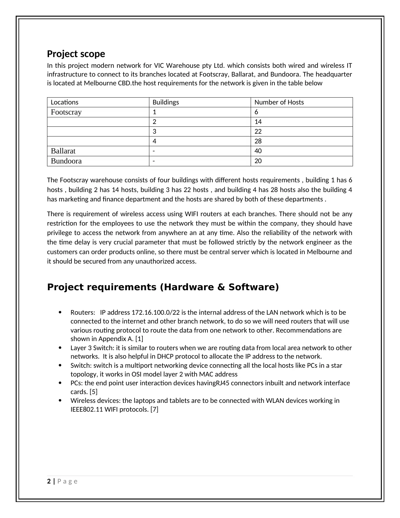
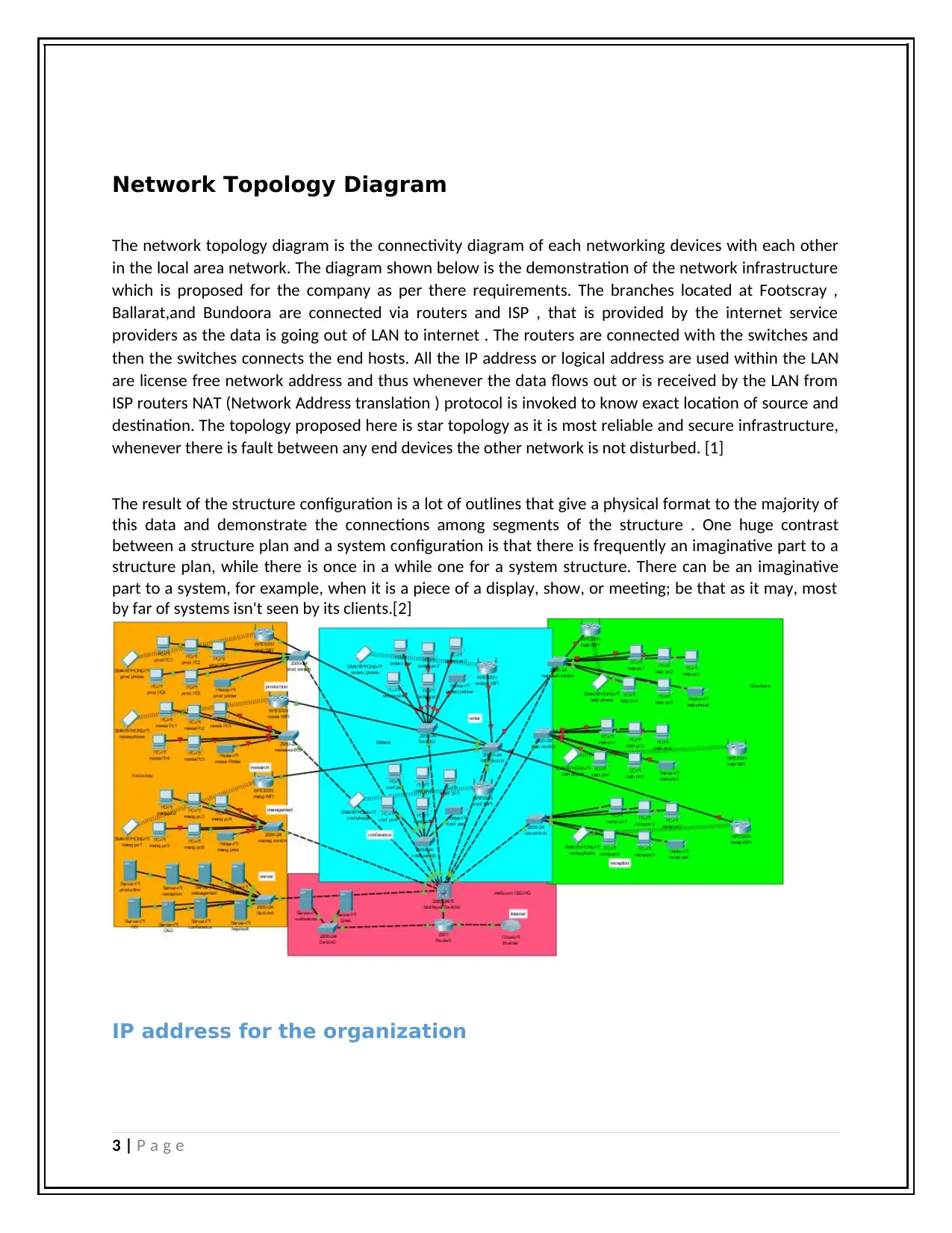
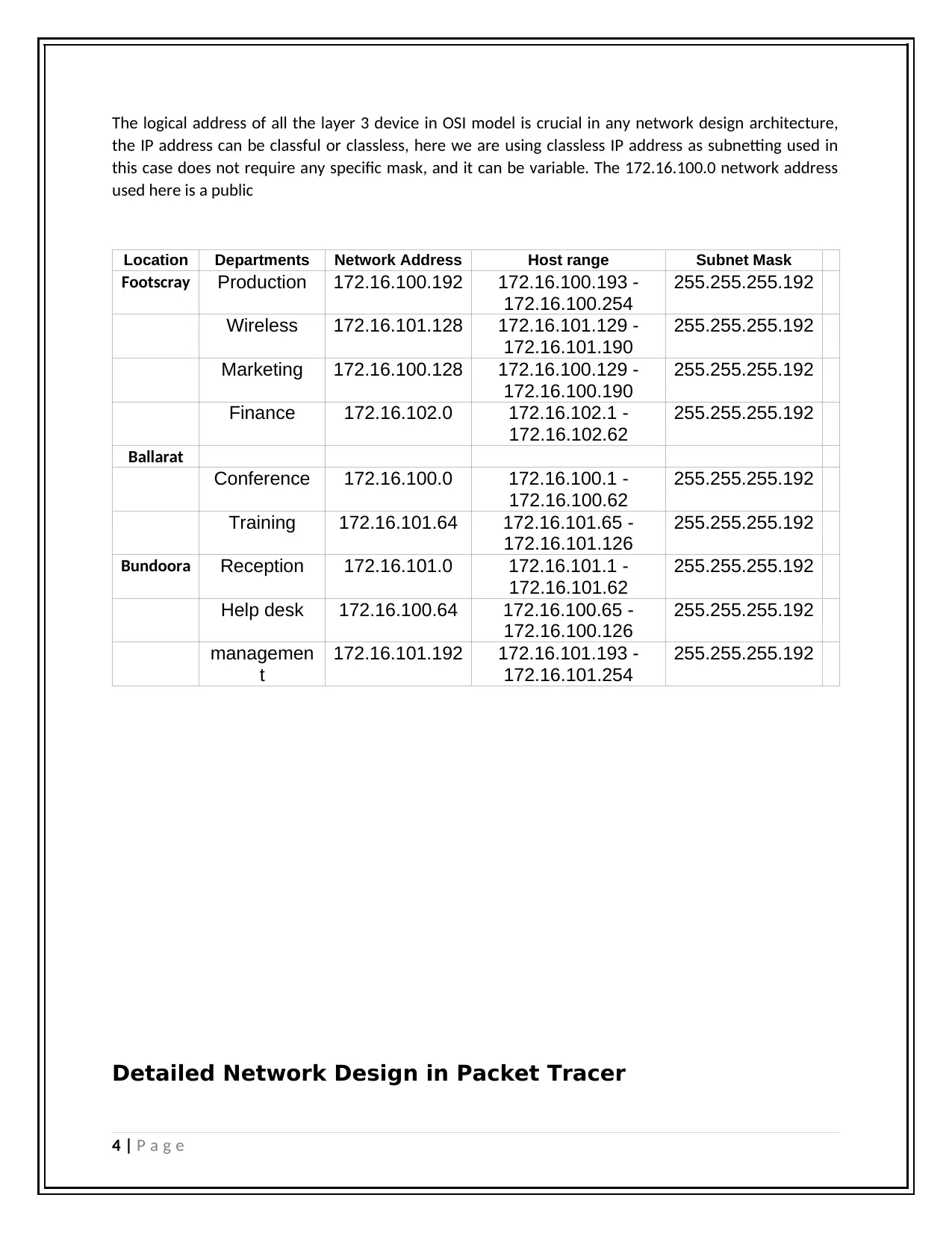
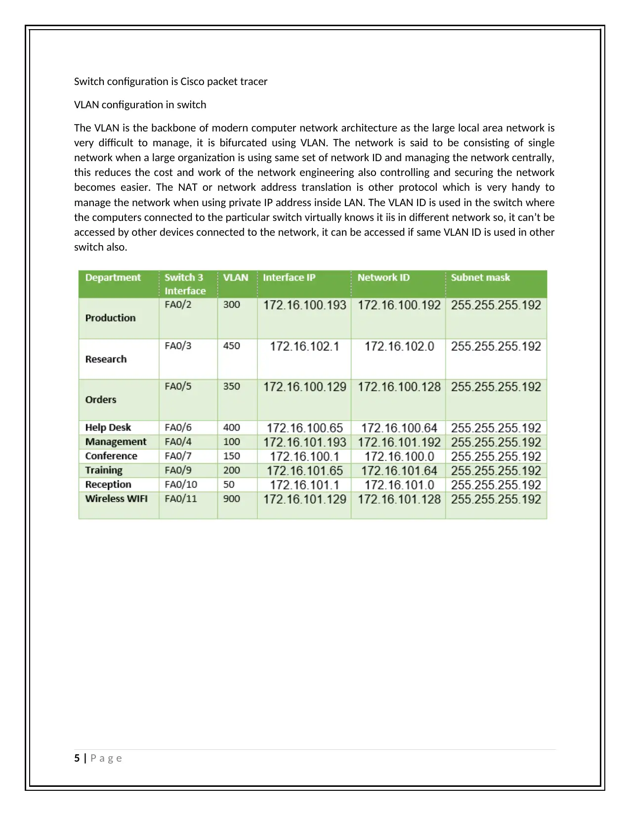
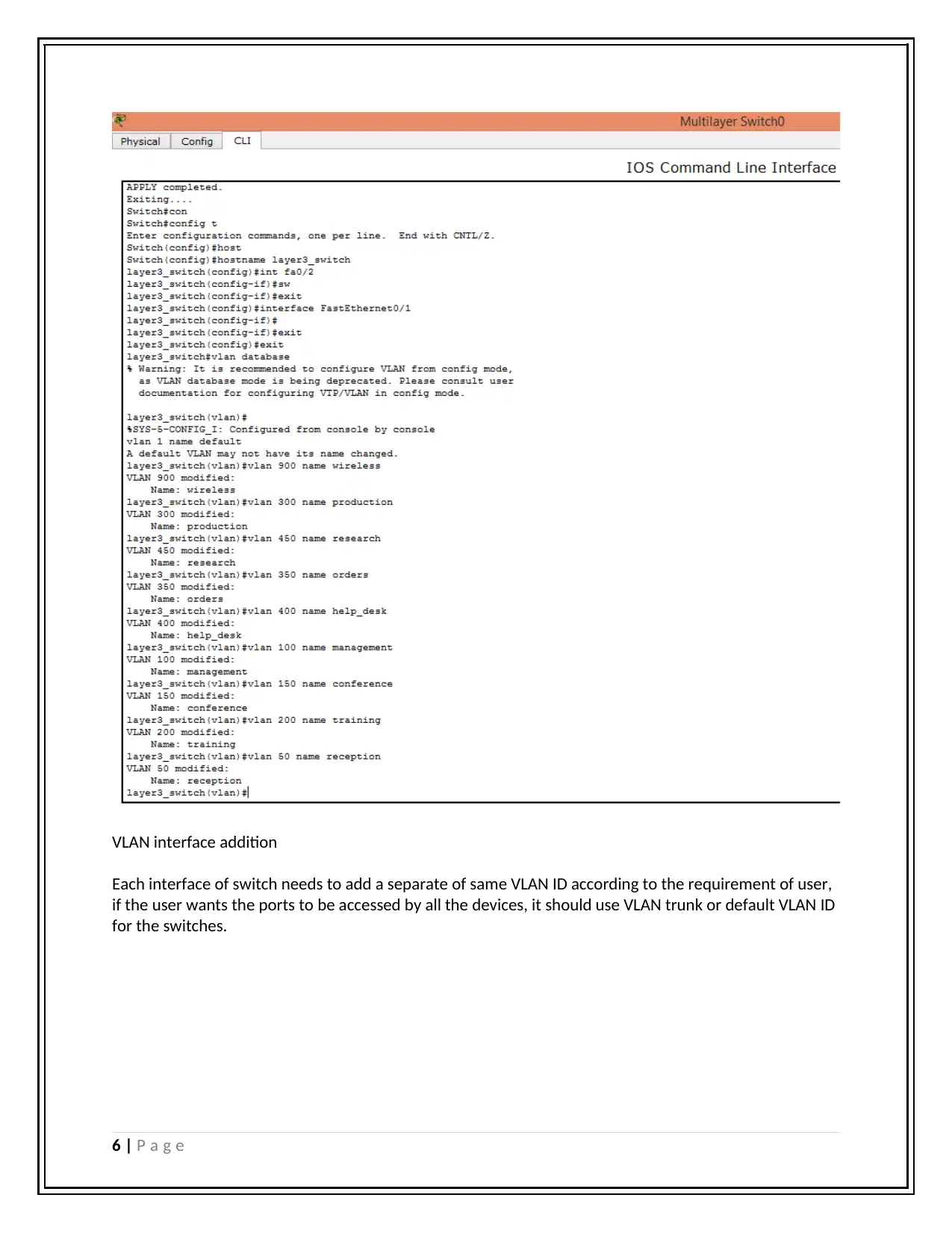
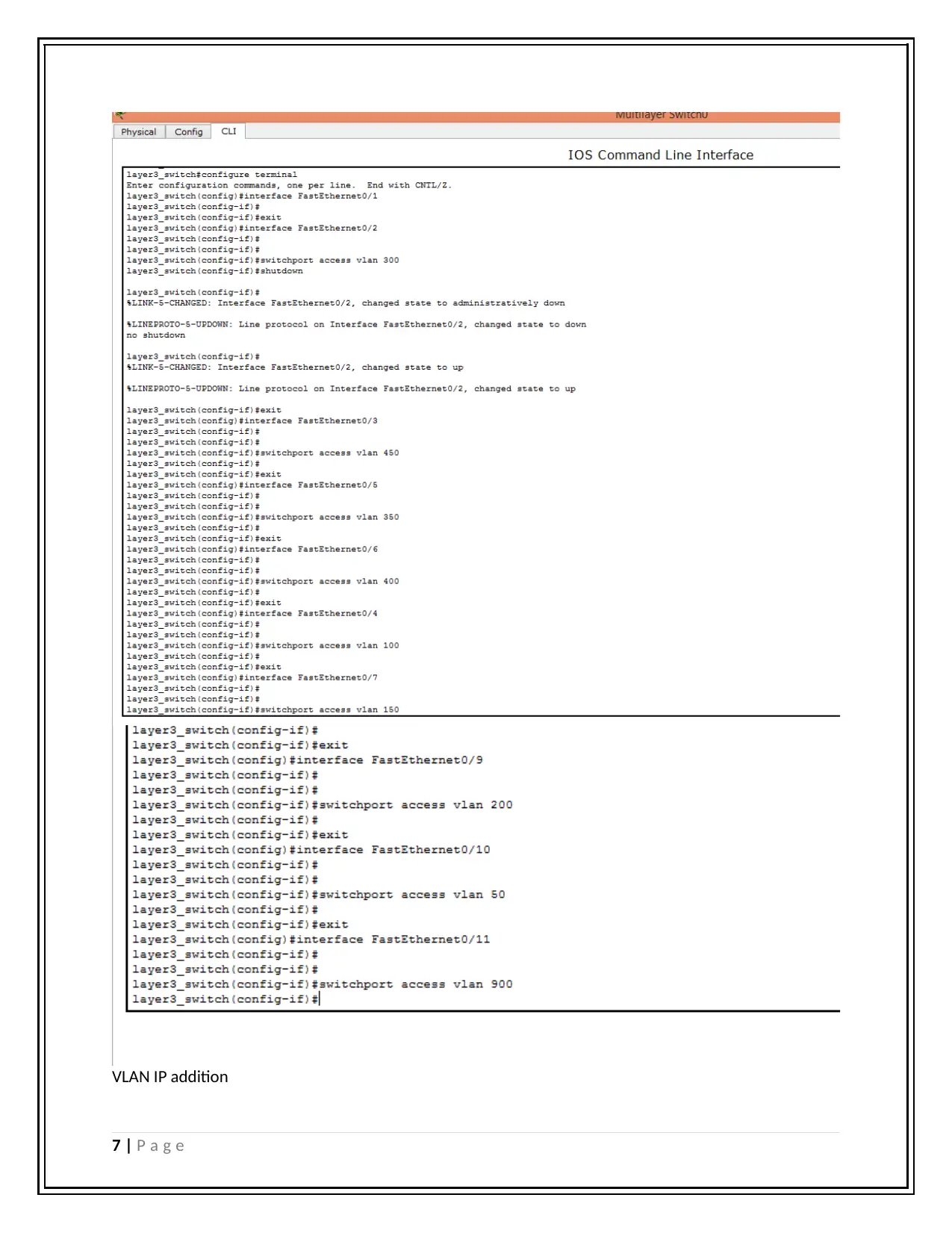
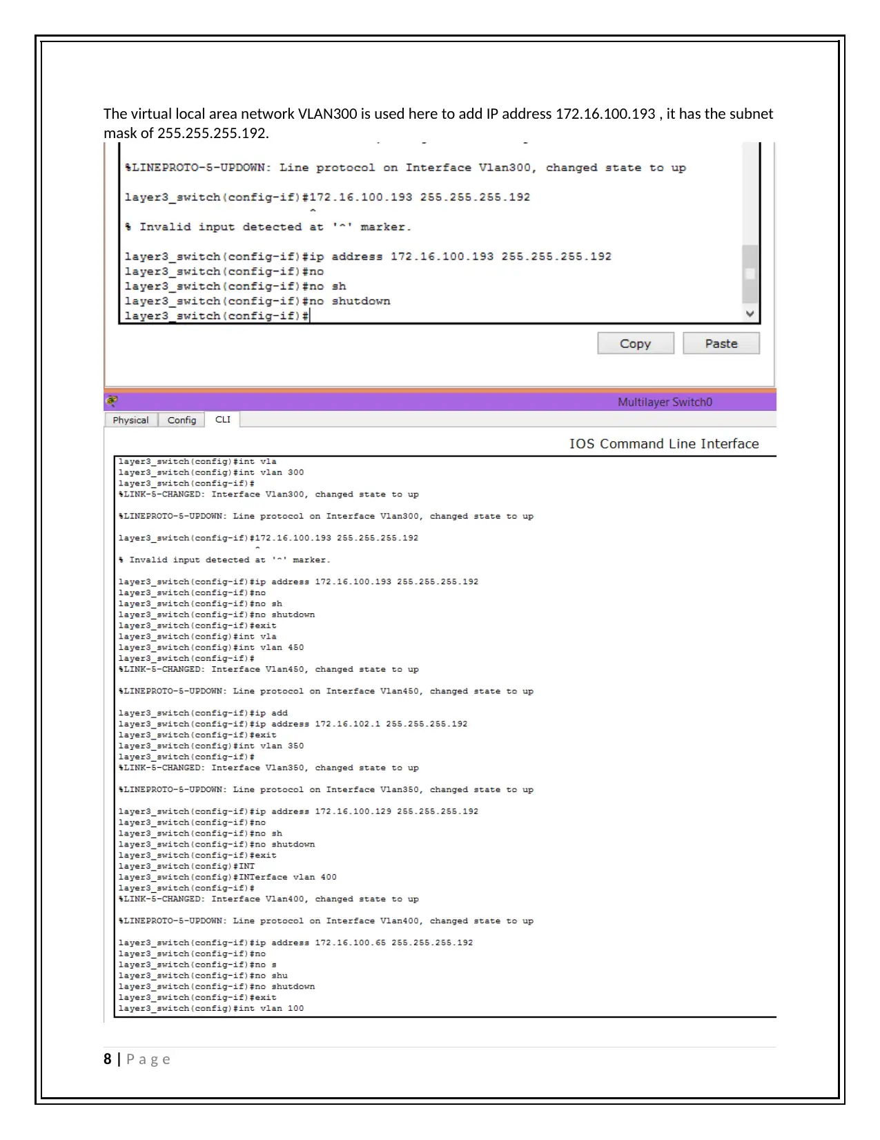
This report details the network requirements analysis and plan for VIC Warehouse pty Ltd., including wired and wireless IT infrastructure across multiple branches. The project scope encompasses the design of a network topology using routers, switches, and wireless devices, considering host requirements for each location. The report specifies IP addressing, VLAN configuration, and DHCP implementation. The network design is simulated using Cisco Packet Tracer, and the network is tested using the PING protocol to ensure successful connectivity and reliability. The conclusion summarizes the network infrastructure, emphasizing connectivity with the internet and secure wireless access for each department using WAP-PSK keys. The report includes references to relevant literature and an appendix detailing networking equipment costs and features.

5/17/2019
Network requirement analysis and plan
BN202
Student Name
[company name]
Network requirement analysis and plan
BN202
Student Name
[company name]
Paraphrase This Document
Need a fresh take? Get an instant paraphrase of this document with our AI Paraphraser

Contents
Project scope...............................................................................................................................................2
Project requirements (Hardware & Software).............................................................................................2
Network Topology Diagram.........................................................................................................................3
IP address for the organization................................................................................................................4
Detailed Network Design in Packet Tracer..................................................................................................5
Testing the Network..................................................................................................................................21
Conclusion.................................................................................................................................................23
References:................................................................................................................................................23
Appendix A: networking devices and cost.................................................................................................24
1 | P a g e

Project scope
In this project modern network for VIC Warehouse pty Ltd. which consists both wired and wireless IT
infrastructure to connect to its branches located at Footscray, Ballarat, and Bundoora. The headquarter
is located at Melbourne CBD.the host requirements for the network is given in the table below
Locations Buildings Number of Hosts
Footscray 1 6
2 14
3 22
4 28
Ballarat - 40
Bundoora - 20
The Footscray warehouse consists of four buildings with different hosts requirements , building 1 has 6
hosts , building 2 has 14 hosts, building 3 has 22 hosts , and building 4 has 28 hosts also the building 4
has marketing and finance department and the hosts are shared by both of these departments .
There is requirement of wireless access using WIFI routers at each branches. There should not be any
restriction for the employees to use the network they must be within the company, they should have
privilege to access the network from anywhere an at any time. Also the reliability of the network with
the time delay is very crucial parameter that must be followed strictly by the network engineer as the
customers can order products online, so there must be central server which is located in Melbourne and
it should be secured from any unauthorized access.
Project requirements (Hardware & Software)
Routers: IP address 172.16.100.0/22 is the internal address of the LAN network which is to be
connected to the internet and other branch network, to do so we will need routers that will use
various routing protocol to route the data from one network to other. Recommendations are
shown in Appendix A. [1]
Layer 3 Switch: it is similar to routers when we are routing data from local area network to other
networks. It is also helpful in DHCP protocol to allocate the IP address to the network.
Switch: switch is a multiport networking device connecting all the local hosts like PCs in a star
topology, it works in OSI model layer 2 with MAC address
PCs: the end point user interaction devices havingRJ45 connectors inbuilt and network interface
cards. [5]
Wireless devices: the laptops and tablets are to be connected with WLAN devices working in
IEEE802.11 WIFI protocols. [7]
2 | P a g e
⊘ This is a preview!⊘
Do you want full access?
Subscribe today to unlock all pages.

Trusted by 1+ million students worldwide

Network Topology Diagram
The network topology diagram is the connectivity diagram of each networking devices with each other
in the local area network. The diagram shown below is the demonstration of the network infrastructure
which is proposed for the company as per there requirements. The branches located at Footscray ,
Ballarat,and Bundoora are connected via routers and ISP , that is provided by the internet service
providers as the data is going out of LAN to internet . The routers are connected with the switches and
then the switches connects the end hosts. All the IP address or logical address are used within the LAN
are license free network address and thus whenever the data flows out or is received by the LAN from
ISP routers NAT (Network Address translation ) protocol is invoked to know exact location of source and
destination. The topology proposed here is star topology as it is most reliable and secure infrastructure,
whenever there is fault between any end devices the other network is not disturbed. [1]
The result of the structure configuration is a lot of outlines that give a physical format to the majority of
this data and demonstrate the connections among segments of the structure . One huge contrast
between a structure plan and a system configuration is that there is frequently an imaginative part to a
structure plan, while there is once in a while one for a system structure. There can be an imaginative
part to a system, for example, when it is a piece of a display, show, or meeting; be that as it may, most
by far of systems isn't seen by its clients.[2]
IP address for the organization
3 | P a g e
Paraphrase This Document
Need a fresh take? Get an instant paraphrase of this document with our AI Paraphraser

The logical address of all the layer 3 device in OSI model is crucial in any network design architecture,
the IP address can be classful or classless, here we are using classless IP address as subnetting used in
this case does not require any specific mask, and it can be variable. The 172.16.100.0 network address
used here is a public
Location Departments Network Address Host range Subnet Mask
Footscray Production 172.16.100.192 172.16.100.193 -
172.16.100.254
255.255.255.192
Wireless 172.16.101.128 172.16.101.129 -
172.16.101.190
255.255.255.192
Marketing 172.16.100.128 172.16.100.129 -
172.16.100.190
255.255.255.192
Finance 172.16.102.0 172.16.102.1 -
172.16.102.62
255.255.255.192
Ballarat
Conference 172.16.100.0 172.16.100.1 -
172.16.100.62
255.255.255.192
Training 172.16.101.64 172.16.101.65 -
172.16.101.126
255.255.255.192
Bundoora Reception 172.16.101.0 172.16.101.1 -
172.16.101.62
255.255.255.192
Help desk 172.16.100.64 172.16.100.65 -
172.16.100.126
255.255.255.192
managemen
t
172.16.101.192 172.16.101.193 -
172.16.101.254
255.255.255.192
Detailed Network Design in Packet Tracer
4 | P a g e

Switch configuration is Cisco packet tracer
VLAN configuration in switch
The VLAN is the backbone of modern computer network architecture as the large local area network is
very difficult to manage, it is bifurcated using VLAN. The network is said to be consisting of single
network when a large organization is using same set of network ID and managing the network centrally,
this reduces the cost and work of the network engineering also controlling and securing the network
becomes easier. The NAT or network address translation is other protocol which is very handy to
manage the network when using private IP address inside LAN. The VLAN ID is used in the switch where
the computers connected to the particular switch virtually knows it iis in different network so, it can’t be
accessed by other devices connected to the network, it can be accessed if same VLAN ID is used in other
switch also.
5 | P a g e
⊘ This is a preview!⊘
Do you want full access?
Subscribe today to unlock all pages.

Trusted by 1+ million students worldwide

VLAN interface addition
Each interface of switch needs to add a separate of same VLAN ID according to the requirement of user,
if the user wants the ports to be accessed by all the devices, it should use VLAN trunk or default VLAN ID
for the switches.
6 | P a g e
Each interface of switch needs to add a separate of same VLAN ID according to the requirement of user,
if the user wants the ports to be accessed by all the devices, it should use VLAN trunk or default VLAN ID
for the switches.
6 | P a g e
Paraphrase This Document
Need a fresh take? Get an instant paraphrase of this document with our AI Paraphraser

VLAN IP addition
7 | P a g e
7 | P a g e

The virtual local area network VLAN300 is used here to add IP address 172.16.100.193 , it has the subnet
mask of 255.255.255.192.
8 | P a g e
mask of 255.255.255.192.
8 | P a g e
⊘ This is a preview!⊘
Do you want full access?
Subscribe today to unlock all pages.

Trusted by 1+ million students worldwide

9 | P a g e
Paraphrase This Document
Need a fresh take? Get an instant paraphrase of this document with our AI Paraphraser

We can see the VLAN used in the network by command show vlan in switch
10 | P a g e
10 | P a g e

Switch 3 as it can be configured to use DHCP , the below configuration in switch 3 is used for DHCP
address allocation to the devices.[8]
11 | P a g e
address allocation to the devices.[8]
11 | P a g e
⊘ This is a preview!⊘
Do you want full access?
Subscribe today to unlock all pages.

Trusted by 1+ million students worldwide
1 out of 31
Related Documents
Your All-in-One AI-Powered Toolkit for Academic Success.
+13062052269
info@desklib.com
Available 24*7 on WhatsApp / Email
Unlock your academic potential
Copyright © 2020–2025 A2Z Services. All Rights Reserved. Developed and managed by ZUCOL.


