University Network Design: Topology, Server Setup, and Configuration

Verified

Added on Ā 2023/01/05

|18
|1165
|8
Project
AI Summary
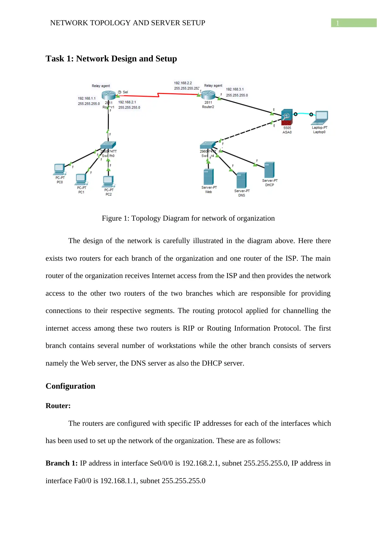
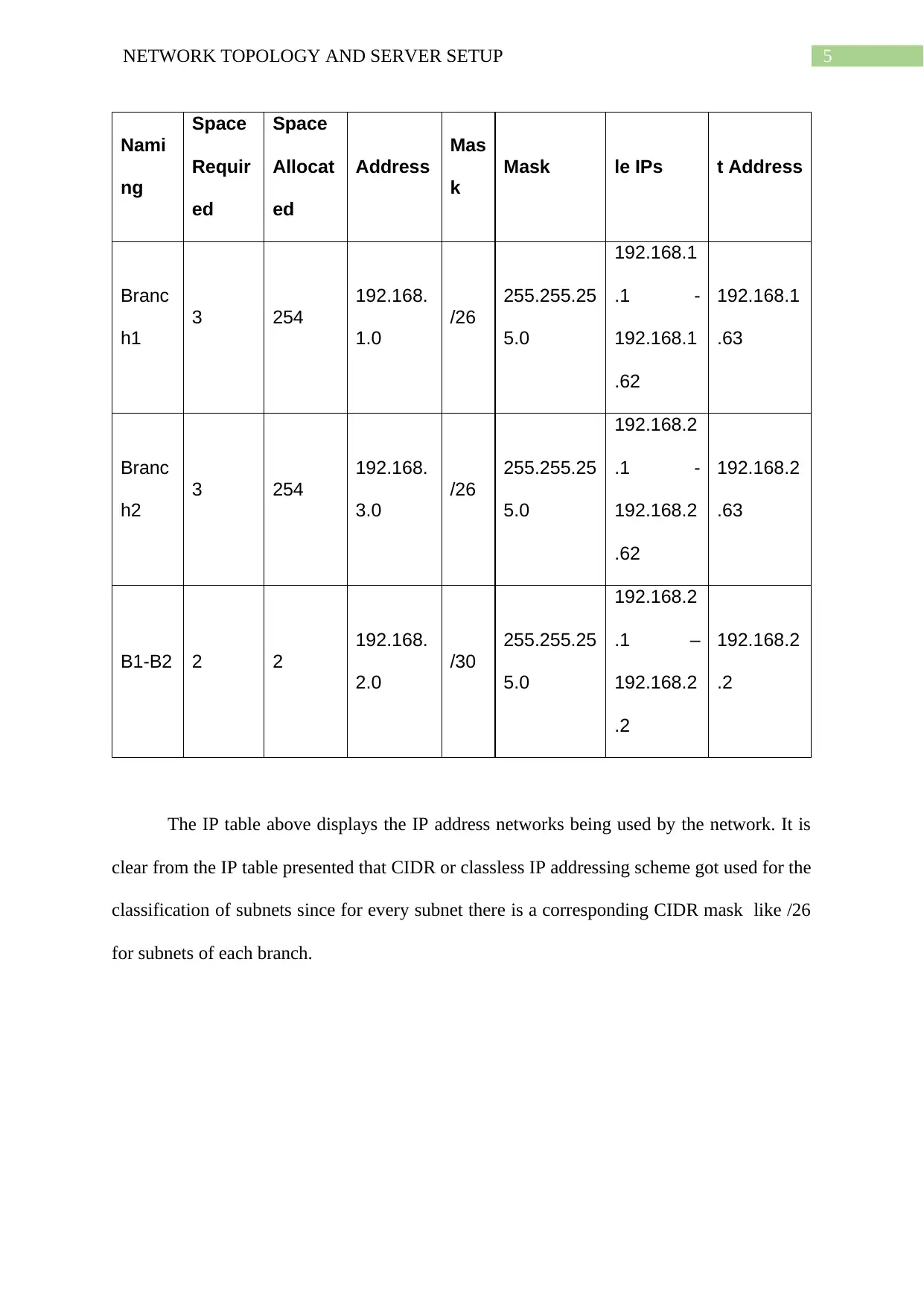
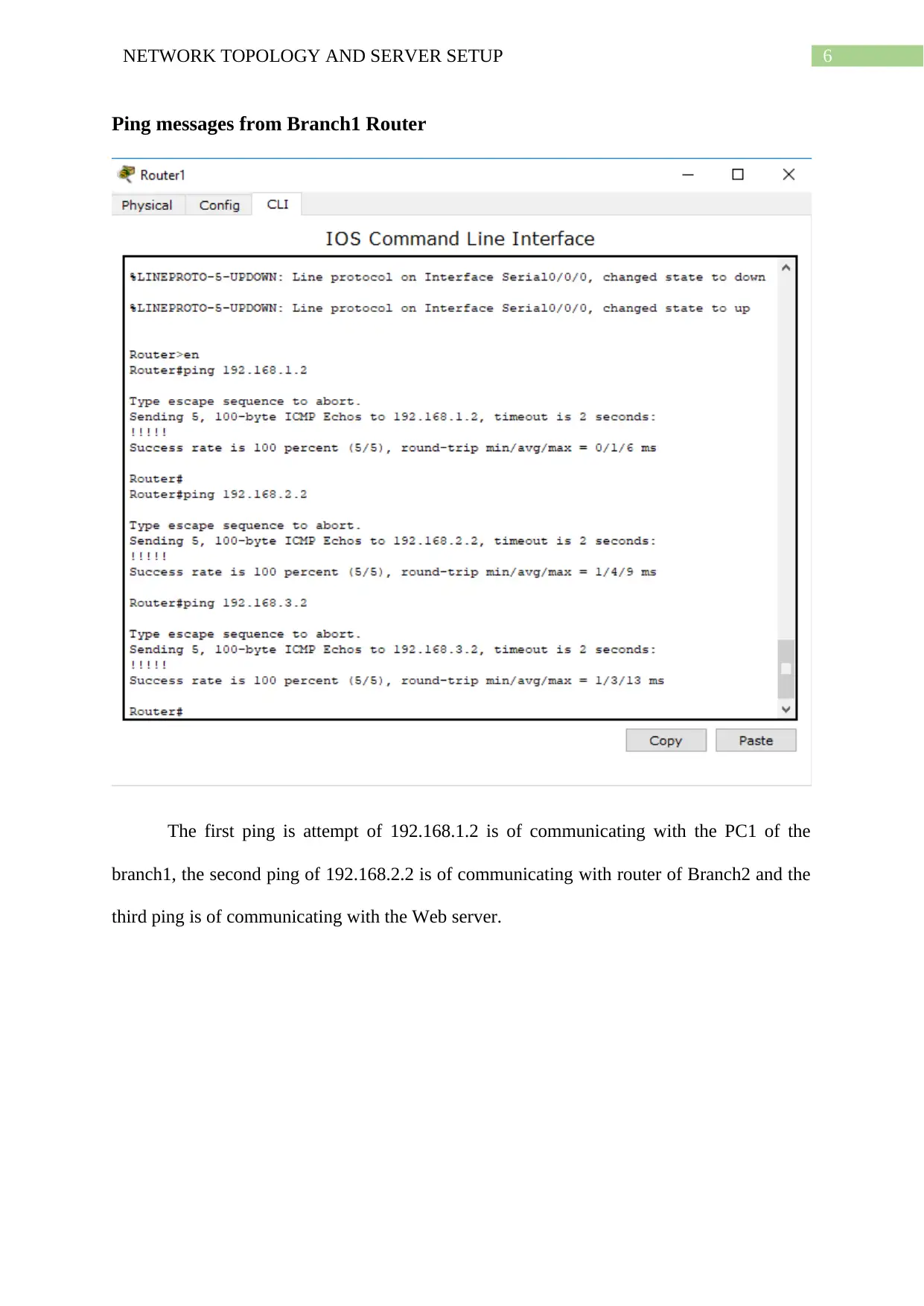
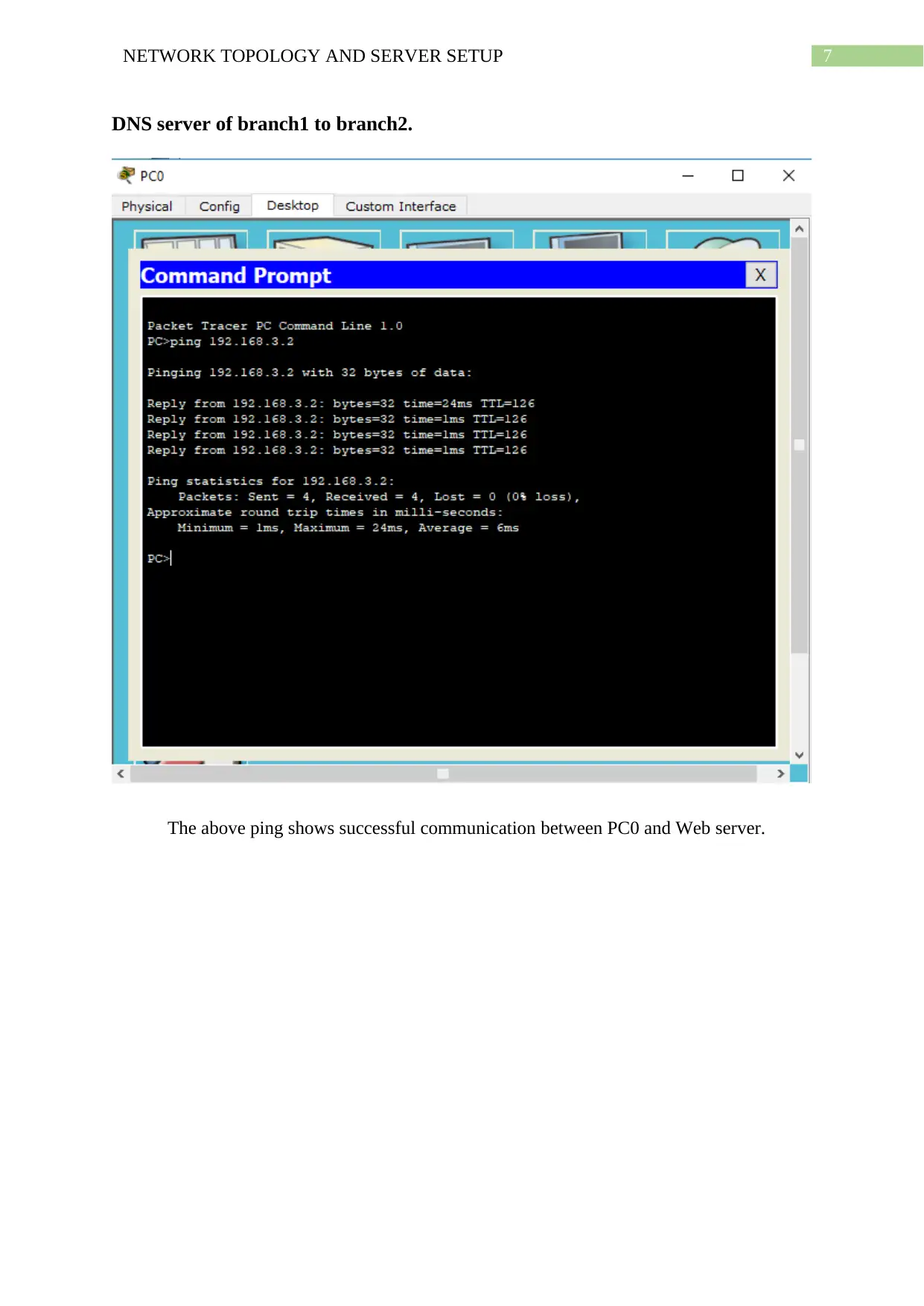
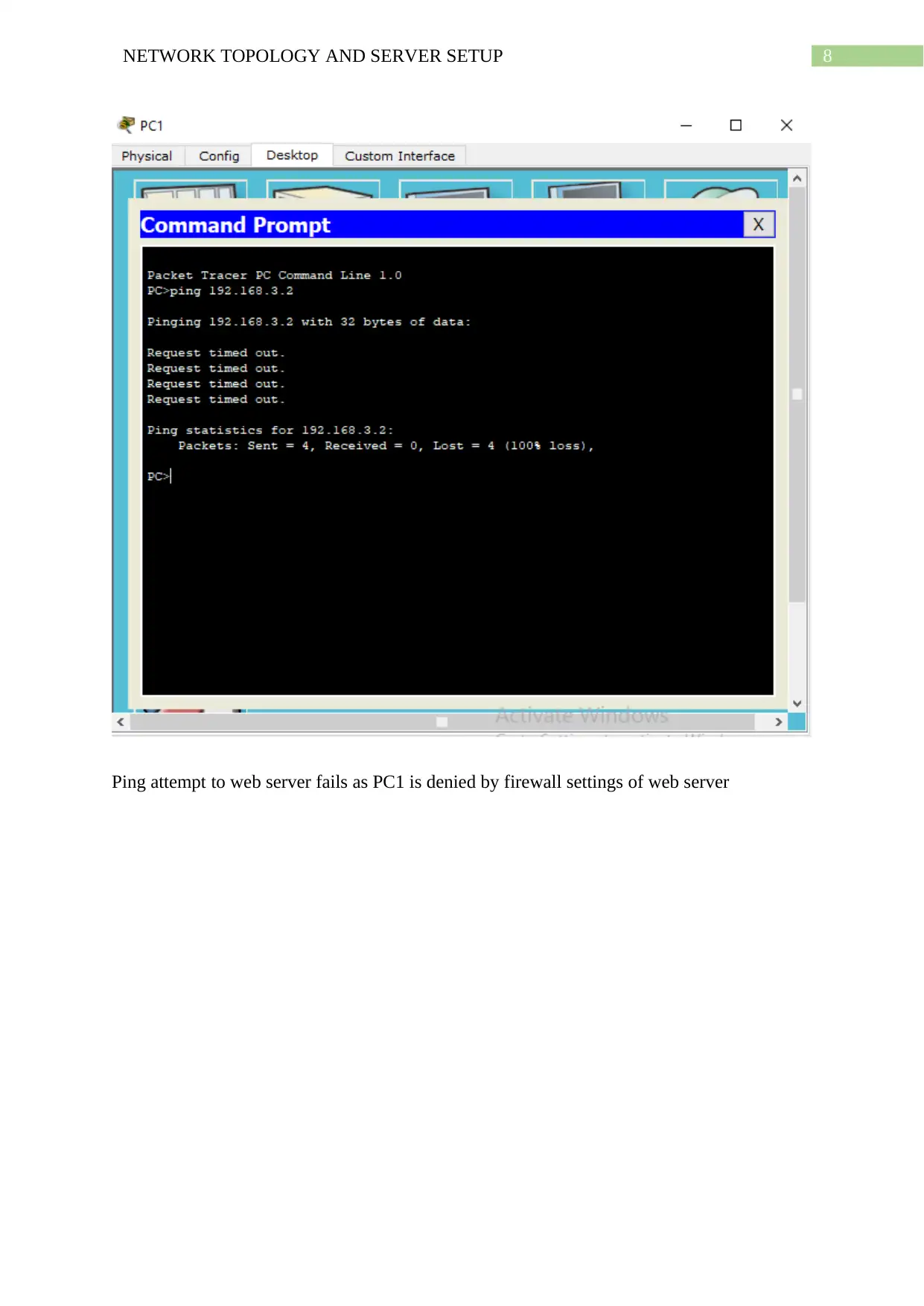
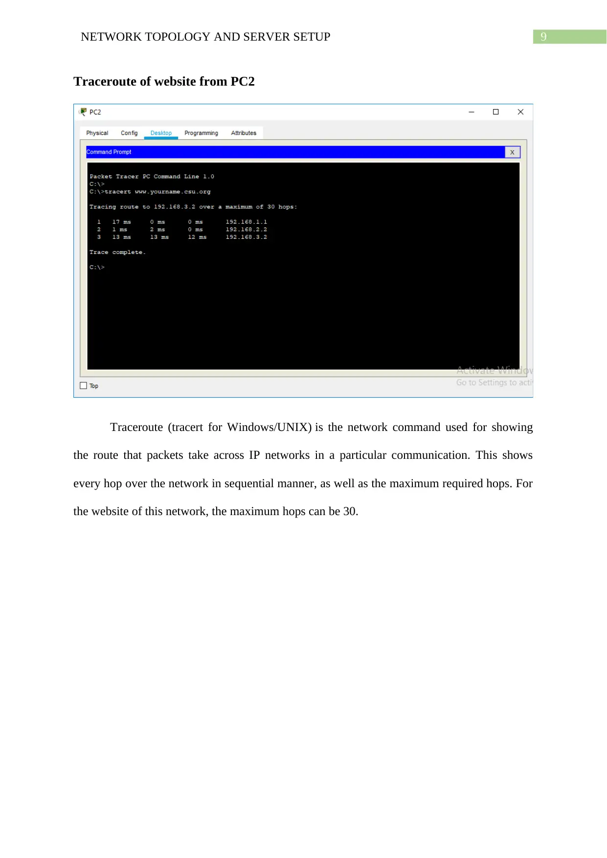
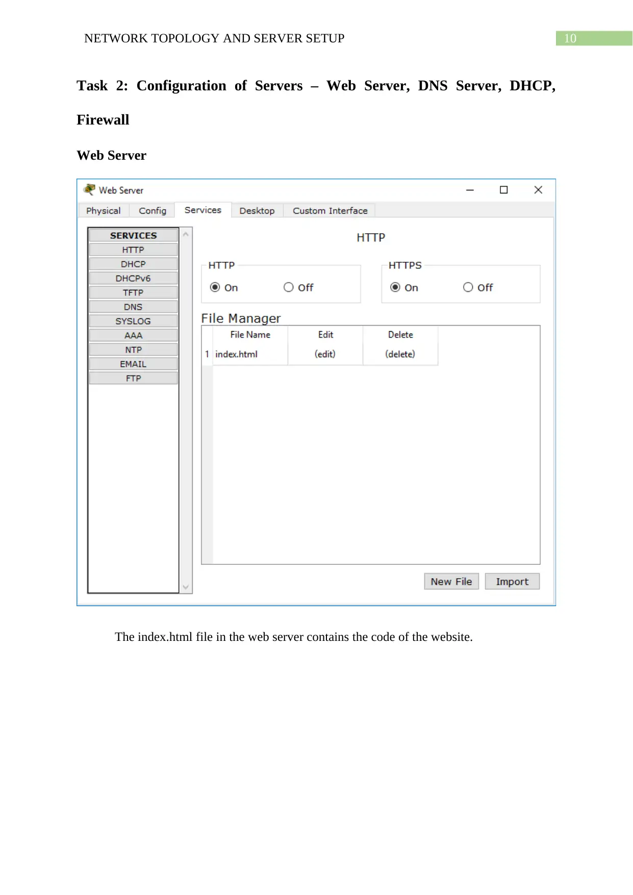
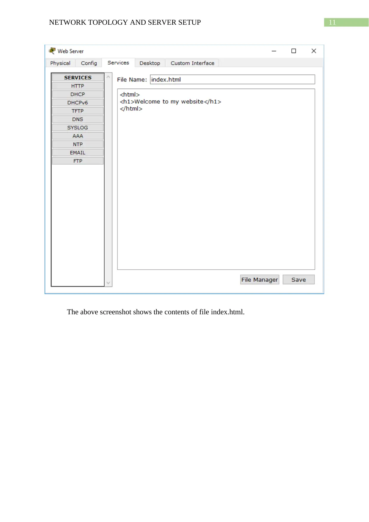
This project report details the design and configuration of a network for an organization, encompassing two branches connected via routers and an ISP. The network utilizes the RIP routing protocol and includes configurations for routers, switches, and servers such as a web server, DNS server, and DHCP server. The report presents IP address and subnet classifications, along with ping and traceroute tests to validate network connectivity and functionality. Server configurations, including the index.html file for the web server, firewall settings, DNS server setup, and DHCP server details, are thoroughly described. The project culminates in demonstrating the functionality of the configured network, including access control lists (ACLs) and website accessibility from various client PCs. The project is supported by a comprehensive bibliography of relevant research papers.
Document Page
Running head: NETWORK TOPOLOGY AND SERVER SETUP
Network Topology and Server Setup
Student Name
University Name
Note by the Author
tabler-icon-diamond-filled.svg

Paraphrase This Document

Need a fresh take? Get an instant paraphrase of this document with our AI Paraphraser
Document Page
1NETWORK TOPOLOGY AND SERVER SETUP
Task 1: Network Design and Setup
Figure 1: Topology Diagram for network of organization
The design of the network is carefully illustrated in the diagram above. Here there
exists two routers for each branch of the organization and one router of the ISP. The main
router of the organization receives Internet access from the ISP and then provides the network
access to the other two routers of the two branches which are responsible for providing
connections to their respective segments. The routing protocol applied for channelling the
internet access among these two routers is RIP or Routing Information Protocol. The first
branch contains several number of workstations while the other branch consists of servers
namely the Web server, the DNS server as also the DHCP server.
Configuration
Router:
The routers are configured with specific IP addresses for each of the interfaces which
has been used to set up the network of the organization. These are as follows:
Branch 1: IP address in interface Se0/0/0 is 192.168.2.1, subnet 255.255.255.0, IP address in
interface Fa0/0 is 192.168.1.1, subnet 255.255.255.0
Document Page
2NETWORK TOPOLOGY AND SERVER SETUP
Branch 2: IP address in interface Se0/0/0 is 192.168.2.2, subnet 255.255.255.0, IP address in
interface Fa0/0 is 192.168.3.1, subnet 255.255.255.0
Document Page
3NETWORK TOPOLOGY AND SERVER SETUP
The RIP routing configuration for all these routers include registration of all the IP networks
in rip mode (router rip). These IP networks are 192.168.1.0, 192.168.2.0 and 192.168.3.0
respectively. The above screenshots validate application of the protocol.
tabler-icon-diamond-filled.svg

Paraphrase This Document

Need a fresh take? Get an instant paraphrase of this document with our AI Paraphraser
Document Page
4NETWORK TOPOLOGY AND SERVER SETUP
Switches: The network uses two different set of VLANs, VLAN 1 for connecting the devices
like workstations and servers to the network.
Servers: Each of the three servers acquire the network access from router and hence contain
the gateway address as router address which is 192.168.3.1.
PCs: The workstations or PCs have their IPs auto assigned by the DHCP server and hence
the gateway address of the PCs are the same as that of the DHCP server which is 192.168.3.1.
IP Address and Subnet Classification
Subn
et
Addre
ss
Addres
s
Network CID
R
Subnet Assignab Broadcas
Document Page
5NETWORK TOPOLOGY AND SERVER SETUP
Nami
ng
Space
Requir
ed
Space
Allocat
ed
Address
Mas
k
Mask le IPs t Address
Branc
h1
3 254
192.168.
1.0
/26
255.255.25
5.0
192.168.1
.1 -
192.168.1
.62
192.168.1
.63
Branc
h2
3 254
192.168.
3.0
/26
255.255.25
5.0
192.168.2
.1 -
192.168.2
.62
192.168.2
.63
B1-B2 2 2
192.168.
2.0
/30
255.255.25
5.0
192.168.2
.1 –
192.168.2
.2
192.168.2
.2
The IP table above displays the IP address networks being used by the network. It is
clear from the IP table presented that CIDR or classless IP addressing scheme got used for the
classification of subnets since for every subnet there is a corresponding CIDR mask like /26
for subnets of each branch.
Document Page
6NETWORK TOPOLOGY AND SERVER SETUP
Ping messages from Branch1 Router
The first ping is attempt of 192.168.1.2 is of communicating with the PC1 of the
branch1, the second ping of 192.168.2.2 is of communicating with router of Branch2 and the
third ping is of communicating with the Web server.
tabler-icon-diamond-filled.svg

Paraphrase This Document

Need a fresh take? Get an instant paraphrase of this document with our AI Paraphraser
Document Page
7NETWORK TOPOLOGY AND SERVER SETUP
DNS server of branch1 to branch2.
The above ping shows successful communication between PC0 and Web server.
Document Page
8NETWORK TOPOLOGY AND SERVER SETUP
Ping attempt to web server fails as PC1 is denied by firewall settings of web server
Document Page
9NETWORK TOPOLOGY AND SERVER SETUP
Traceroute of website from PC2
Traceroute (tracert for Windows/UNIX) is the network command used for showing
the route that packets take across IP networks in a particular communication. This shows
every hop over the network in sequential manner, as well as the maximum required hops. For
the website of this network, the maximum hops can be 30.
tabler-icon-diamond-filled.svg

Paraphrase This Document

Need a fresh take? Get an instant paraphrase of this document with our AI Paraphraser
Document Page
10NETWORK TOPOLOGY AND SERVER SETUP
Task 2: Configuration of Servers – Web Server, DNS Server, DHCP,
Firewall
Web Server
The index.html file in the web server contains the code of the website.
Document Page
11NETWORK TOPOLOGY AND SERVER SETUP
The above screenshot shows the contents of file index.html.
chevron_up_icon
1 out of 18
circle_padding
hide_on_mobile
zoom_out_icon
[object Object]