TCP/IP Networking Project - Network Configuration and Service Setup

Verified

Added on  2021/06/17

|16
|1018
|104
Project
AI Summary
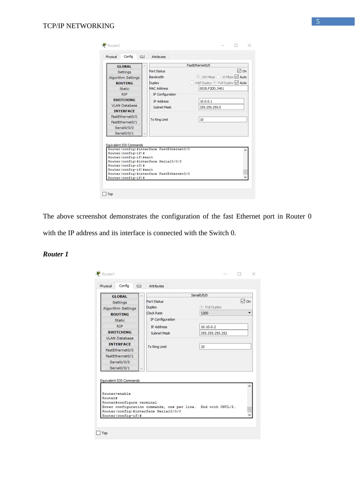
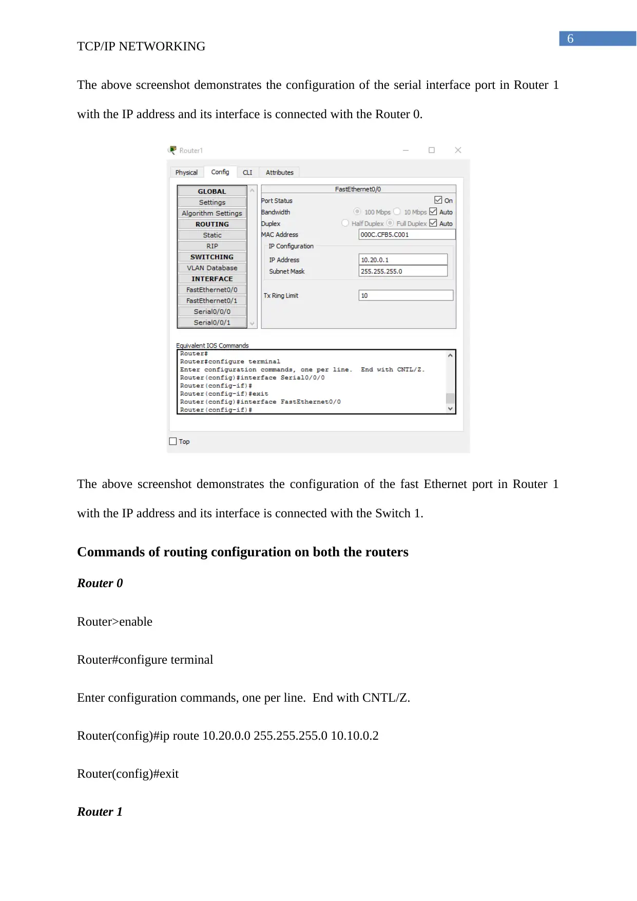
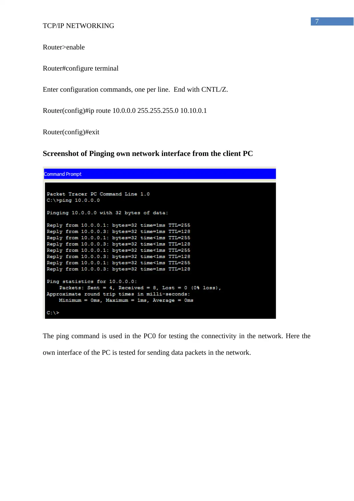
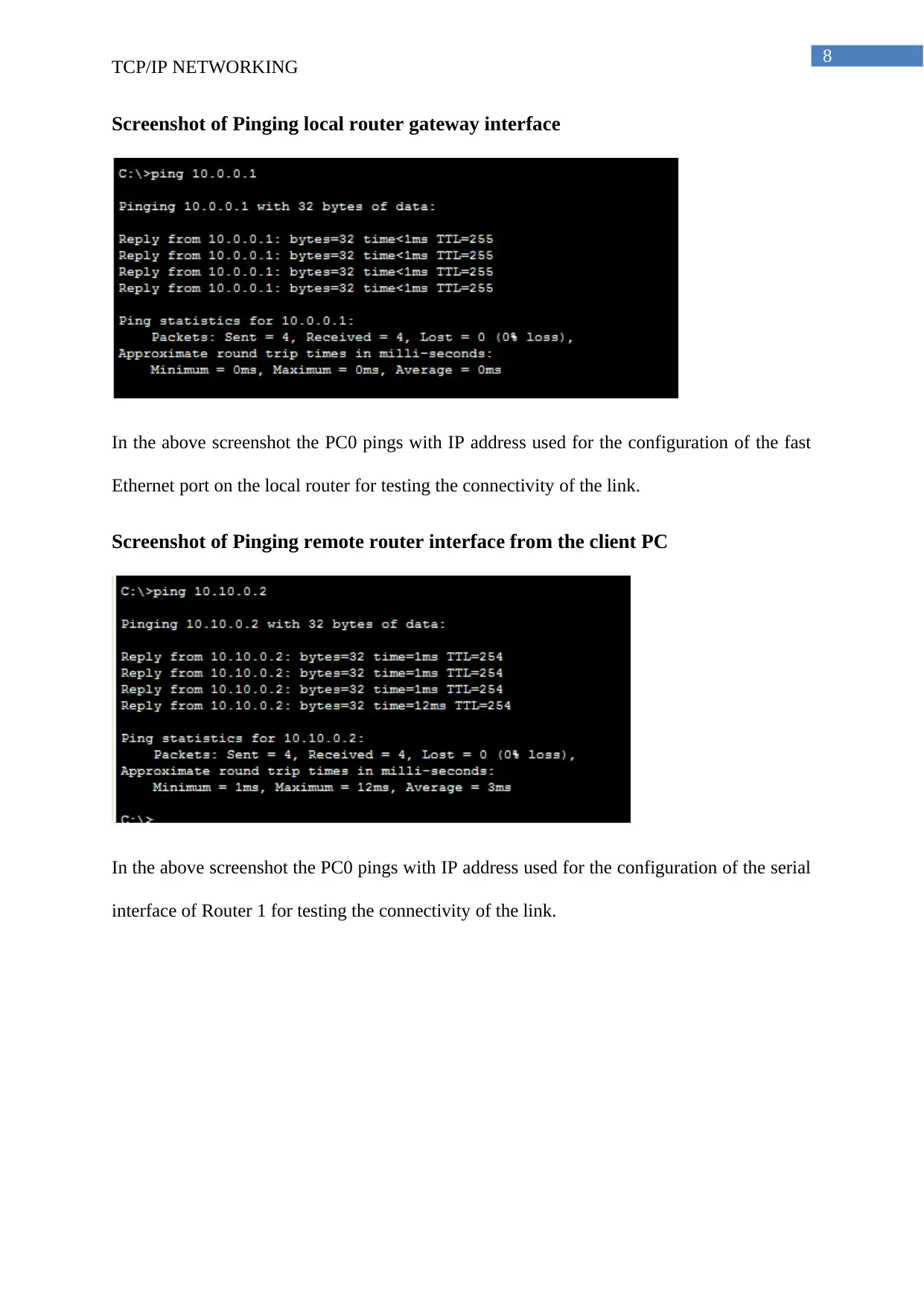
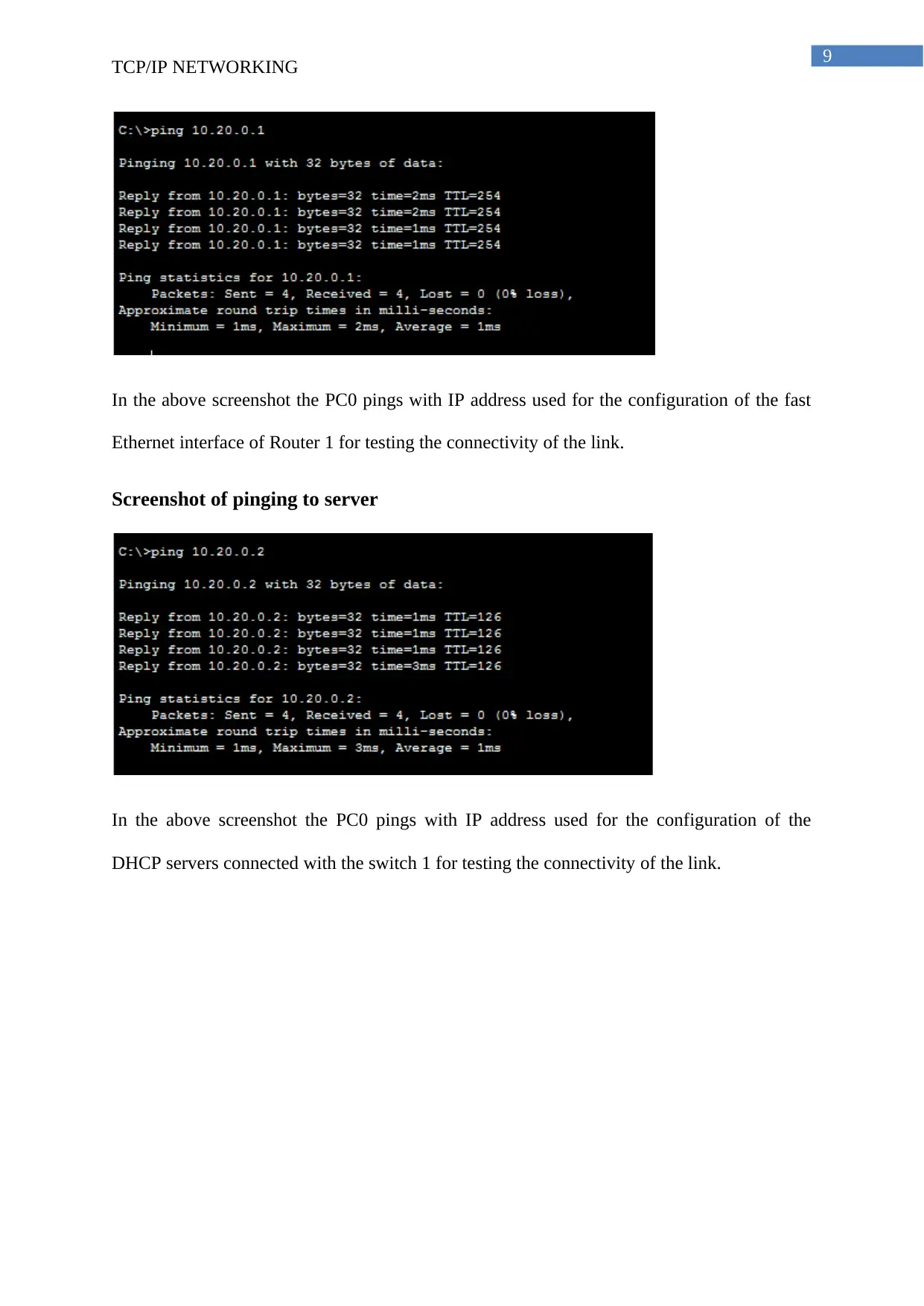
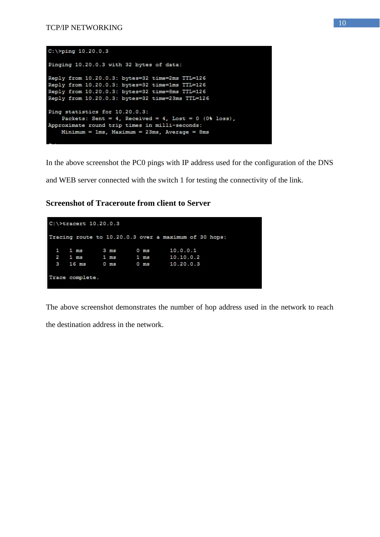
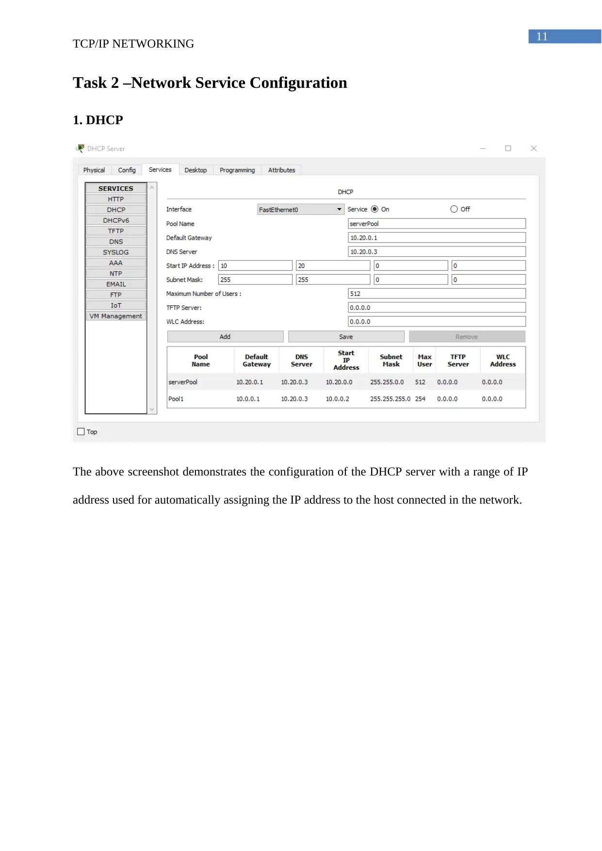
This project report details the configuration and implementation of a TCP/IP network using Cisco Packet Tracer. The project is divided into two main tasks: setting up the network and configuring network services. Task 1 focuses on configuring PCs, servers (including DNS and Web servers), and routers. Screenshots illustrate IP address allocation, routing configurations, and ping tests to verify connectivity across the network. Task 2 covers the configuration of DHCP for automatic IP assignment, the setup of a Web and DNS server, and the implementation of a firewall using access control lists to restrict access to the web server. The report includes commands, screenshots, and a bibliography of relevant sources.
Document Page
Running head: TCP/IP NETWORKING
TCP/IP Networking
Name of the Student
Name of the University
Author’s Note
tabler-icon-diamond-filled.svg

Paraphrase This Document

Need a fresh take? Get an instant paraphrase of this document with our AI Paraphraser
Document Page
1
TCP/IP NETWORKING
Table of Contents
Task 1 – Setting up a network....................................................................................................2
Screenshot of PC Configuration.............................................................................................2
Screenshot of Server Configuration.......................................................................................3
Screenshot of Router Configuration.......................................................................................4
Commands of routing configuration on both the routers.......................................................6
Screenshot of Pinging own network interface from the client PC.........................................7
Screenshot of Pinging local router gateway interface............................................................8
Screenshot of Pinging remote router interface from the client PC........................................8
Screenshot of pinging to server..............................................................................................9
Screenshot of Traceroute from client to Server...................................................................10
Task 2 –Network Service Configuration..................................................................................11
1. DHCP...............................................................................................................................11
2. WEB and DNS Server......................................................................................................12
4. Firewall............................................................................................................................14
Bibliography.............................................................................................................................15
Document Page
2
TCP/IP NETWORKING
Task 1 – Setting up a network
Screenshot of PC Configuration
The above screenshot shows the allocation of IP address to the PC 0 connect with the switch
0.
Document Page
3
TCP/IP NETWORKING
Screenshot of Server Configuration
WEB and DNS Server
The above screenshot demonstrates the configuration of the DNS and WEB server with the IP
address and it is connected with the switch 1.
DHCP Server
tabler-icon-diamond-filled.svg

Paraphrase This Document

Need a fresh take? Get an instant paraphrase of this document with our AI Paraphraser
Document Page
4
TCP/IP NETWORKING
The above screenshot demonstrates the configuration of the DHCP server with the IP address
and it is connected with the switch 1.
Screenshot of Router Configuration
Router 0 Configuration
The above screenshot demonstrates the configuration of the serial port in Router 0 with the IP
address and its interface is connected with the Router 0
Document Page
5
TCP/IP NETWORKING
The above screenshot demonstrates the configuration of the fast Ethernet port in Router 0
with the IP address and its interface is connected with the Switch 0.
Router 1
Document Page
6
TCP/IP NETWORKING
The above screenshot demonstrates the configuration of the serial interface port in Router 1
with the IP address and its interface is connected with the Router 0.
The above screenshot demonstrates the configuration of the fast Ethernet port in Router 1
with the IP address and its interface is connected with the Switch 1.
Commands of routing configuration on both the routers
Router 0
Router>enable
Router#configure terminal
Enter configuration commands, one per line. End with CNTL/Z.
Router(config)#ip route 10.20.0.0 255.255.255.0 10.10.0.2
Router(config)#exit
Router 1
tabler-icon-diamond-filled.svg

Paraphrase This Document

Need a fresh take? Get an instant paraphrase of this document with our AI Paraphraser
Document Page
7
TCP/IP NETWORKING
Router>enable
Router#configure terminal
Enter configuration commands, one per line. End with CNTL/Z.
Router(config)#ip route 10.0.0.0 255.255.255.0 10.10.0.1
Router(config)#exit
Screenshot of Pinging own network interface from the client PC
The ping command is used in the PC0 for testing the connectivity in the network. Here the
own interface of the PC is tested for sending data packets in the network.
Document Page
8
TCP/IP NETWORKING
Screenshot of Pinging local router gateway interface
In the above screenshot the PC0 pings with IP address used for the configuration of the fast
Ethernet port on the local router for testing the connectivity of the link.
Screenshot of Pinging remote router interface from the client PC
In the above screenshot the PC0 pings with IP address used for the configuration of the serial
interface of Router 1 for testing the connectivity of the link.
Document Page
9
TCP/IP NETWORKING
In the above screenshot the PC0 pings with IP address used for the configuration of the fast
Ethernet interface of Router 1 for testing the connectivity of the link.
Screenshot of pinging to server
In the above screenshot the PC0 pings with IP address used for the configuration of the
DHCP servers connected with the switch 1 for testing the connectivity of the link.
tabler-icon-diamond-filled.svg

Paraphrase This Document

Need a fresh take? Get an instant paraphrase of this document with our AI Paraphraser
Document Page
10
TCP/IP NETWORKING
In the above screenshot the PC0 pings with IP address used for the configuration of the DNS
and WEB server connected with the switch 1 for testing the connectivity of the link.
Screenshot of Traceroute from client to Server
The above screenshot demonstrates the number of hop address used in the network to reach
the destination address in the network.
Document Page
11
TCP/IP NETWORKING
Task 2 –Network Service Configuration
1. DHCP
The above screenshot demonstrates the configuration of the DHCP server with a range of IP
address used for automatically assigning the IP address to the host connected in the network.
chevron_up_icon
1 out of 16
circle_padding
hide_on_mobile
zoom_out_icon
[object Object]