Network Design Document Project for Orange Site Network Solution
VerifiedAdded on 2021/06/17
|28
|7511
|217
Project
AI Summary
This document presents a comprehensive network design project for the Orange site, aiming to establish a secure and efficient network infrastructure. It begins with an executive summary outlining the project's goals, which include configuring servers with Active Directory, DNS, DHCP, and other services, designing LAN and WAN networks, and establishing a site-to-site VPN connection. The logical design details the network's structure, including subnetting, VLANs, and the selection of hardware components. An IP addressing scheme is provided, and the document explores routing and switching protocols, emphasizing security measures such as firewalls and access control lists. The physical design covers network topology, LAN and WAN technologies, and server/PC requirements. The project also includes a test plan to validate the network's functionality and performance. The document analyzes routing metrics, addresses security considerations, and details the setup of wireless technologies. It provides a thorough overview of the network design process, from initial planning to implementation and testing.
Network Design Document
Project Client Organisation:
Contact:
System Name <<To be created by team and client>>
Date of Design
Document
<<Date of this version>>
Document Status Draft / Approved <<delete one>>
Document Reference <<FileName.doc>>
Version Number Version 1<<update as necessary, in whole numbers>>
Prepared by <<Technical Writer>>
Team Members << Names of other team members>>
7630317365527025157.docx 1 of 31
Paraphrase This Document
Need a fresh take? Get an instant paraphrase of this document with our AI Paraphraser

7630317365527025157.docx 2 of 31
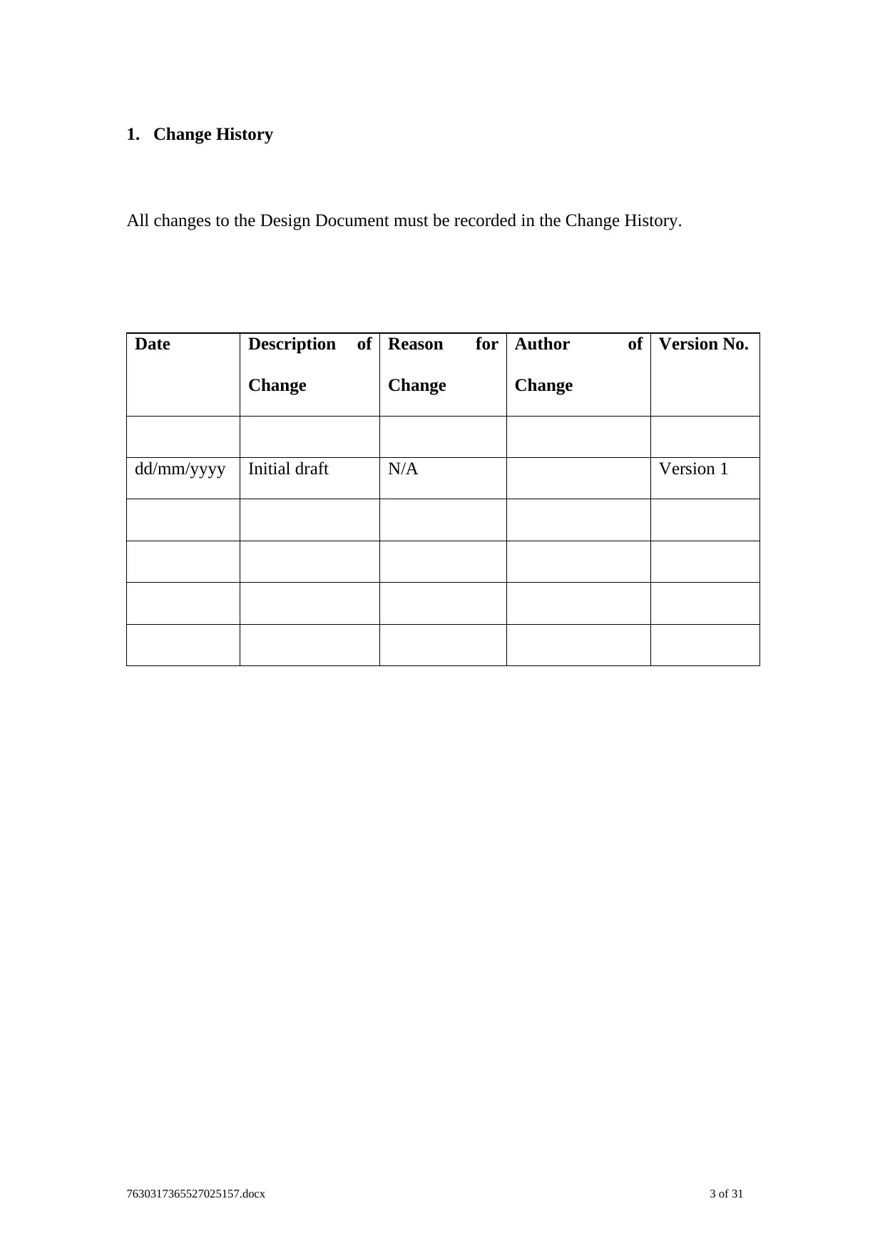
1. Change History
All changes to the Design Document must be recorded in the Change History.
Date Description of
Change
Reason for
Change
Author of
Change
Version No.
dd/mm/yyyy Initial draft N/A Version 1
7630317365527025157.docx 3 of 31
All changes to the Design Document must be recorded in the Change History.
Date Description of
Change
Reason for
Change
Author of
Change
Version No.
dd/mm/yyyy Initial draft N/A Version 1
7630317365527025157.docx 3 of 31
⊘ This is a preview!⊘
Do you want full access?
Subscribe today to unlock all pages.
Trusted by 1+ million students worldwide
2. Table of Contents
1. CHANGE HISTORY..............................................................................................................................3
2. TABLE OF CONTENTS........................................................................................................................4
3. EXECUTIVE SUMMARY.....................................................................................................................5
4. PROJECT GOALS..................................................................................................................................6
5. LOGICAL DESIGN................................................................................................................................7
5.1. LOGICAL NETWORK DIAGRAM.........................................................................................................7
5.2. ADDRESSING AND NAMING STRUCTURE..........................................................................................7
5.3. ROUTING AND SWITCHING PROTOCOLS...........................................................................................8
5.4. SECURITY........................................................................................................................................11
5.5. VIRTUAL LANS..............................................................................................................................12
5.6. WIRELESS NETWORKS....................................................................................................................12
5.7. QOS DESIGN...................................................................................................................................13
5.8. NETWORK MANAGEMENT..............................................................................................................14
6. PHYSICAL DESIGN............................................................................................................................15
6.1. NETWORK TOPOLOGY.....................................................................................................................15
6.2. LAN TECHNOLOGIES......................................................................................................................16
6.3. WAN TECHNOLOGIES.....................................................................................................................17
6.4. PHYSICAL NETWORK DIAGRAM.....................................................................................................18
6.5. MINIMAL SERVER AND PC REQUIREMENTS....................................................................................19
6.6. WIRELESS TECHNOLOGIES..............................................................................................................20
7. TEST PLAN...........................................................................................................................................22
7.1. OVERALL PROJECT SCOPE AND OBJECTIVE...................................................................................22
7.2. TEST OBJECTIVE AND SUCCESS CRITERIA.......................................................................................22
7.3. TEST RESOURCE REQUIRED.............................................................................................................22
7.4. TEST SCHEDULE..............................................................................................................................22
7630317365527025157.docx 4 of 31
Paraphrase This Document
Need a fresh take? Get an instant paraphrase of this document with our AI Paraphraser

7.5. DEVELOPMENT OF THE TEST CASES................................................................................................23
8. REFERENCES.......................................................................................................................................24
7630317365527025157.docx 5 of 31
8. REFERENCES.......................................................................................................................................24
7630317365527025157.docx 5 of 31
3. Executive Summary
The report is prepared for the development of a network solution for the Orange site
and connect it with the other branches with the establishment of a VPN connection
between the other sites. The network is designed with the preparation of an IP addressing
plan and documented in the report for the management of the current network
infrastructure of the organization. The report is prepared by documenting the major goals
of the organization and the scope for the further improvement of the network design. A
logical design of the network is prepared and attached with the report for providing a brief
overview of the network design. A proper addressing and naming scheme is followed for
the development of the network and assigning an IP address to all the interface of the
network device installed in the network. The IP addressing scheme is used for
configuration of the servers with DHCP such that it can be used for automatically assign
the IP address to nodes connected in network. The routing and the switching protocol used
for the configuration of the network are analysed and the routers are configured with the
routing protocol such that it can be used for communicating with the hosts connected with
the interface of the other branches of the organization. The security measures that should
be implemented for the development of the network solution is analysed for securing the
network. The network management strategy that should be followed for management of
network resources are also documented in report. The physical network design is also
attached with the report with the details of the network topology selected for the
development of the local area network and the wide area network of the organization. A
physical network diagram is attached with the report for providing an overview of the
network and the minimum server and the Pc requirement that should be used for network
are also given in the report. It also defines the wireless technologies that can be
7630317365527025157.docx 6 of 31
⊘ This is a preview!⊘
Do you want full access?
Subscribe today to unlock all pages.
Trusted by 1+ million students worldwide
implemented for enabling the users to connect their wireless devices with the network are
discussed.
4. Project Goals
The main goals identified for the development of the network framework for the
organization is listed below:
To configure the servers with the active directory, DNS, DHCP, File, Firewall,
Backups, MYSQL and Hyper V Cluster.
To create a network design for the LAN and the WAN and create a site to site VPN
link between the sites for enabling secure communication between the sites
To connect the hosts with the network and build the Pc following the minimum
configuration
To configure the routers and the servers with a proper IP addressing plan enabling
routing for allocate address for each of the VLAN used for breaking the network
into different subnets.
To create different VLAN in the switch and provide a proper name to the VLAN
for easy management of the network and monitor the activity of the users
connected in the network.
To configure the firewall in the windows server for restricting the outside users to
access the core resources of the organizational network and align the business rules
for the development of the firewall policy.
To configure the active directory such that the users can be grouped and privilege
must be provided to them for restricting them to modify the network configuration
To create a backup of the server and add redundancy in the network such that it
can be used for handing disaster recovery
7630317365527025157.docx 7 of 31
Paraphrase This Document
Need a fresh take? Get an instant paraphrase of this document with our AI Paraphraser
To virtualize the servers such it can be migrated to the cloud platform for
increasing the scalability of the network.
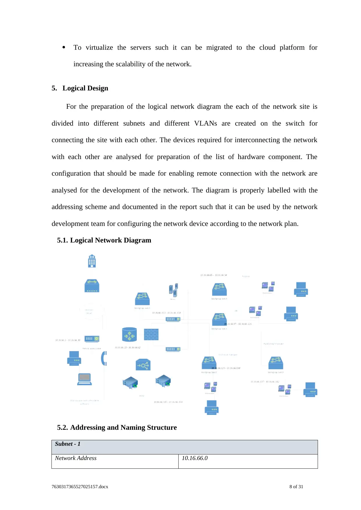
5. Logical Design
For the preparation of the logical network diagram the each of the network site is
divided into different subnets and different VLANs are created on the switch for
connecting the site with each other. The devices required for interconnecting the network
with each other are analysed for preparation of the list of hardware component. The
configuration that should be made for enabling remote connection with the network are
analysed for the development of the network. The diagram is properly labelled with the
addressing scheme and documented in the report such that it can be used by the network
development team for configuring the network device according to the network plan.
5.1. Logical Network Diagram
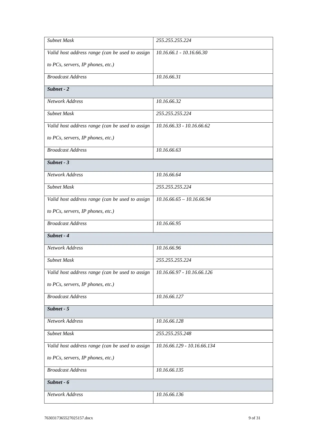
5.2. Addressing and Naming Structure
Subnet - 1
Network Address 10.16.66.0
7630317365527025157.docx 8 of 31
increasing the scalability of the network.
5. Logical Design
For the preparation of the logical network diagram the each of the network site is
divided into different subnets and different VLANs are created on the switch for
connecting the site with each other. The devices required for interconnecting the network
with each other are analysed for preparation of the list of hardware component. The
configuration that should be made for enabling remote connection with the network are
analysed for the development of the network. The diagram is properly labelled with the
addressing scheme and documented in the report such that it can be used by the network
development team for configuring the network device according to the network plan.
5.1. Logical Network Diagram
5.2. Addressing and Naming Structure
Subnet - 1
Network Address 10.16.66.0
7630317365527025157.docx 8 of 31
Subnet Mask 255.255.255.224
Valid host address range (can be used to assign
to PCs, servers, IP phones, etc.)
10.16.66.1 - 10.16.66.30
Broadcast Address 10.16.66.31
Subnet - 2
Network Address 10.16.66.32
Subnet Mask 255.255.255.224
Valid host address range (can be used to assign
to PCs, servers, IP phones, etc.)
10.16.66.33 - 10.16.66.62
Broadcast Address 10.16.66.63
Subnet - 3
Network Address 10.16.66.64
Subnet Mask 255.255.255.224
Valid host address range (can be used to assign
to PCs, servers, IP phones, etc.)
10.16.66.65 – 10.16.66.94
Broadcast Address 10.16.66.95
Subnet - 4
Network Address 10.16.66.96
Subnet Mask 255.255.255.224
Valid host address range (can be used to assign
to PCs, servers, IP phones, etc.)
10.16.66.97 - 10.16.66.126
Broadcast Address 10.16.66.127
Subnet - 5
Network Address 10.16.66.128
Subnet Mask 255.255.255.248
Valid host address range (can be used to assign
to PCs, servers, IP phones, etc.)
10.16.66.129 - 10.16.66.134
Broadcast Address 10.16.66.135
Subnet - 6
Network Address 10.16.66.136
7630317365527025157.docx 9 of 31
Valid host address range (can be used to assign
to PCs, servers, IP phones, etc.)
10.16.66.1 - 10.16.66.30
Broadcast Address 10.16.66.31
Subnet - 2
Network Address 10.16.66.32
Subnet Mask 255.255.255.224
Valid host address range (can be used to assign
to PCs, servers, IP phones, etc.)
10.16.66.33 - 10.16.66.62
Broadcast Address 10.16.66.63
Subnet - 3
Network Address 10.16.66.64
Subnet Mask 255.255.255.224
Valid host address range (can be used to assign
to PCs, servers, IP phones, etc.)
10.16.66.65 – 10.16.66.94
Broadcast Address 10.16.66.95
Subnet - 4
Network Address 10.16.66.96
Subnet Mask 255.255.255.224
Valid host address range (can be used to assign
to PCs, servers, IP phones, etc.)
10.16.66.97 - 10.16.66.126
Broadcast Address 10.16.66.127
Subnet - 5
Network Address 10.16.66.128
Subnet Mask 255.255.255.248
Valid host address range (can be used to assign
to PCs, servers, IP phones, etc.)
10.16.66.129 - 10.16.66.134
Broadcast Address 10.16.66.135
Subnet - 6
Network Address 10.16.66.136
7630317365527025157.docx 9 of 31
⊘ This is a preview!⊘
Do you want full access?
Subscribe today to unlock all pages.
Trusted by 1+ million students worldwide
Subnet Mask 255.255.255.248
Valid host address range (can be used to assign
to PCs, servers, IP phones, etc.)
10.16.66.137 - 10.16.66.142
Broadcast Address 10.16.66.143
Subnet - 7
Network Address 10.16.66.144
Subnet Mask 255.255.255.248
Valid host address range (can be used to assign
to PCs, servers, IP phones, etc.)
10.16.66.145 - 10.16.66.150
Broadcast Address 10.16.66.151
Subnet - 8
Network Address 10.16.66.152
Subnet Mask 255.255.255.248
Valid host address range (can be used to assign
to PCs, servers, IP phones, etc.)
10.16.66.153 - 10.16.66.158
Broadcast Address 10.16.66.159
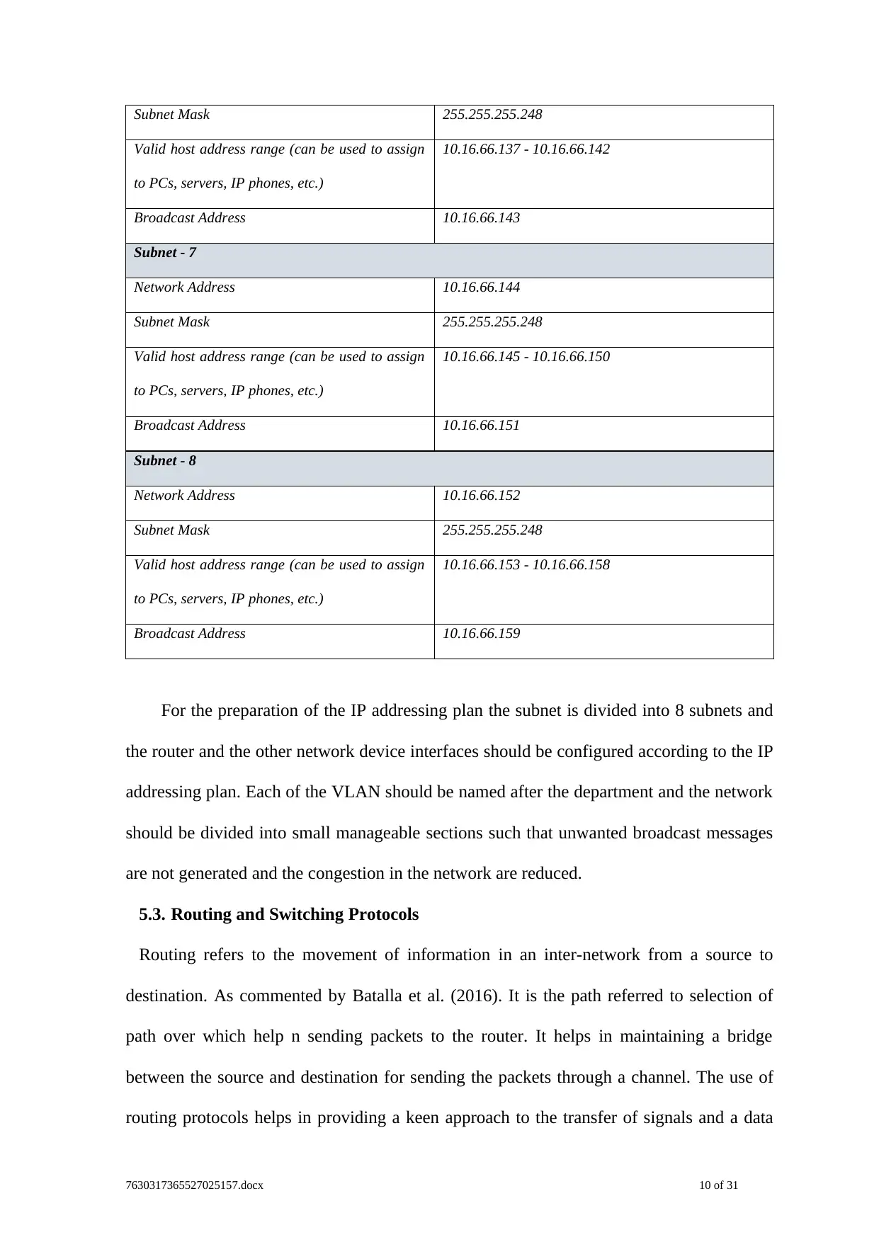
For the preparation of the IP addressing plan the subnet is divided into 8 subnets and
the router and the other network device interfaces should be configured according to the IP
addressing plan. Each of the VLAN should be named after the department and the network
should be divided into small manageable sections such that unwanted broadcast messages
are not generated and the congestion in the network are reduced.
5.3. Routing and Switching Protocols
Routing refers to the movement of information in an inter-network from a source to
destination. As commented by Batalla et al. (2016). It is the path referred to selection of
path over which help n sending packets to the router. It helps in maintaining a bridge
between the source and destination for sending the packets through a channel. The use of
routing protocols helps in providing a keen approach to the transfer of signals and a data
7630317365527025157.docx 10 of 31
Valid host address range (can be used to assign
to PCs, servers, IP phones, etc.)
10.16.66.137 - 10.16.66.142
Broadcast Address 10.16.66.143
Subnet - 7
Network Address 10.16.66.144
Subnet Mask 255.255.255.248
Valid host address range (can be used to assign
to PCs, servers, IP phones, etc.)
10.16.66.145 - 10.16.66.150
Broadcast Address 10.16.66.151
Subnet - 8
Network Address 10.16.66.152
Subnet Mask 255.255.255.248
Valid host address range (can be used to assign
to PCs, servers, IP phones, etc.)
10.16.66.153 - 10.16.66.158
Broadcast Address 10.16.66.159
For the preparation of the IP addressing plan the subnet is divided into 8 subnets and
the router and the other network device interfaces should be configured according to the IP
addressing plan. Each of the VLAN should be named after the department and the network
should be divided into small manageable sections such that unwanted broadcast messages
are not generated and the congestion in the network are reduced.
5.3. Routing and Switching Protocols
Routing refers to the movement of information in an inter-network from a source to
destination. As commented by Batalla et al. (2016). It is the path referred to selection of
path over which help n sending packets to the router. It helps in maintaining a bridge
between the source and destination for sending the packets through a channel. The use of
routing protocols helps in providing a keen approach to the transfer of signals and a data
7630317365527025157.docx 10 of 31
Paraphrase This Document
Need a fresh take? Get an instant paraphrase of this document with our AI Paraphraser
packets through the channel between source and destination. The distinction helps in
routing and bridging with different data and information with help of moving information
from source to destination. However, the routing algorithm is a part of network layer
software that is responsible for the transfer of data packets through a channel.
As mentioned by Javed, Afzal & Kim (2018), routing protocols uses metrics for
evaluating the path bandwidth and reliability of the routing algorithm for determining
optimal path to destination. This include the destination information and address. Routing
algorithm helps in filling routing tables with a variety of information. When a switch gets
an appropriate function, it starts checking goal deliver and endeavours to connect this
address with a next jump. As stated by Velez et al. (2015), by dissecting various updates
from single other switch, a switch can create an image of the system topology. There are
various routing algorithm metrics that helps in determining the best route. Some of the
routing metrics have been discussed below:
Path length: As commented by Vinel et al. (2016), it is a common routing metric. This
protocol helps in allowing network administrators for assigning arbitrary costs to each
network link. Path length refers to cost of cost included in each link traversed. Other
routing protocols helps in defining hop count that include number of passes in the
internetworking products.
Routing delay: As mentioned by Sampei (2017),it refers to the length of time required
for moving the packets from source to destination by internet. However, delay depends on
various factors that include bandwidth of medium internet links.
Bandwidth: It refers to availability traffic capacity of link. Every single other thing being
equivalent, a 10-Mbps Ethernet connection would be desirable over a 64-kbps rented line.
In spite of the fact that transmission capacity is a rating of the most extreme achievable
throughput on a connection, courses through connections with more noteworthy data
transfer capacity do not really give preferred courses over courses through slower
7630317365527025157.docx 11 of 31
interfaces. For instance, if a quicker connection is busier, real time required to send a
parcel to goal could be more prominent.
Load: As commented by El-Bawab et al. (2018), it alludes to how much a system asset,
for example, a switch, is occupied. Load can be computed in an assortment of ways,
including CPU usage and parcels prepared every second. Observing these parameters
consistently can be asset serious itself.
Communication cost: It is another critical metric, particularly in light of the fact that a
few organizations may not think about execution as much as they think about working
consumptions. In spite of the fact that line postponement might be longer, they will send
parcels over their own lines as opposed to through people in general lines that cost cash for
use time.
As mentioned by Zinner et al. 2017), reliability with regards to steering calculations,
alludes to the constancy (normally depicted as far as the bit-mistake rate) of each system
interface. Some system connections may go down more frequently than others. After a
system comes up short, certain system connections may be repaired more effectively or
more rapidly than different connections. Any unwavering quality factor can be considered
in the task of the dependability evaluations, which are discretionary numeric qualities,
typically appointed to arrange connects by organize managers.
5.4. Security
For securing the network from illegal access different security measures can be
applied and it is the key for the success of the network. Different factors should be
considered such as location of the firewalls, devices installed in the DMZ zone, Access
control list and the VPN tunnelling for end to end point connection. The firewall should be
installed in the entry point of the DMZ zone such that the access of the resources in the
DMZ zone should be restricted and another firewall should be installed in the exit point
such that the internal and the external network can be secured from the illegal access. For
7630317365527025157.docx 12 of 31
⊘ This is a preview!⊘
Do you want full access?
Subscribe today to unlock all pages.
Trusted by 1+ million students worldwide
1 out of 28
Related Documents


Your All-in-One AI-Powered Toolkit for Academic Success.
+13062052269
info@desklib.com
Available 24*7 on WhatsApp / Email
![[object Object]](/_next/static/media/star-bottom.7253800d.svg)
Unlock your academic potential
Copyright © 2020–2026 A2Z Services. All Rights Reserved. Developed and managed by ZUCOL.