Networking Technologies - BTEC HND Unit 24 Assignment Report
VerifiedAdded on 2023/03/30
|16
|2830
|225
Report
AI Summary
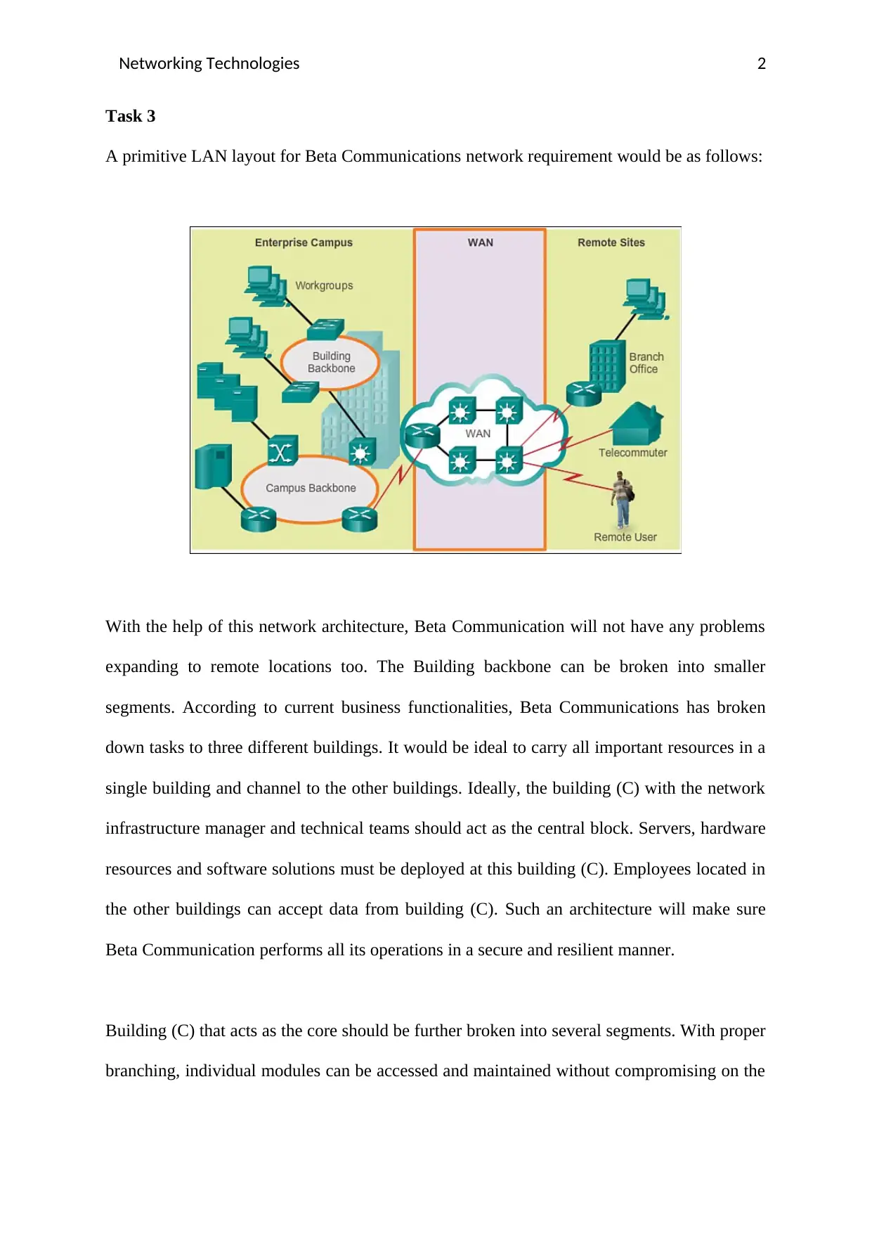
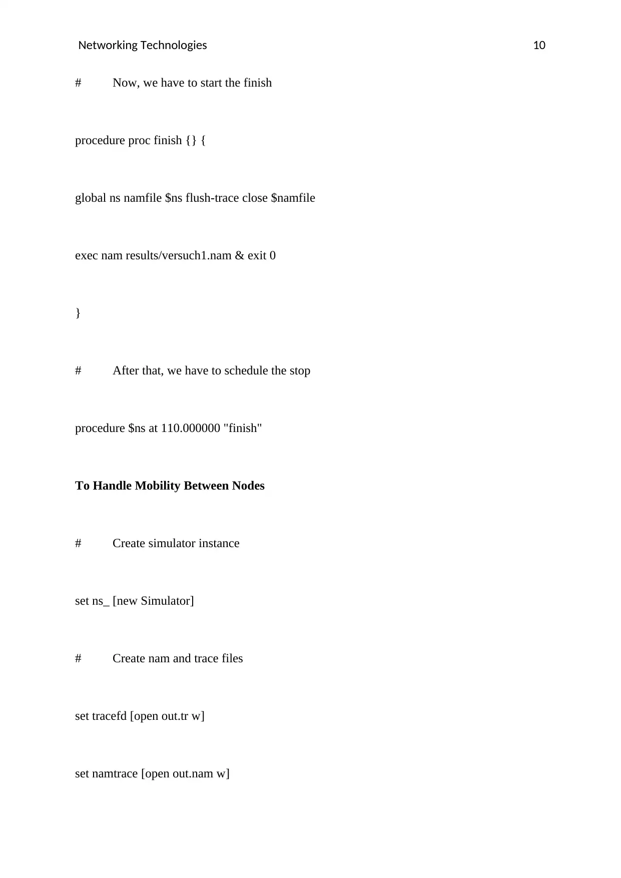
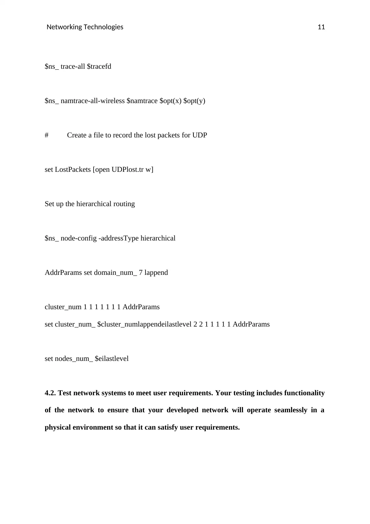
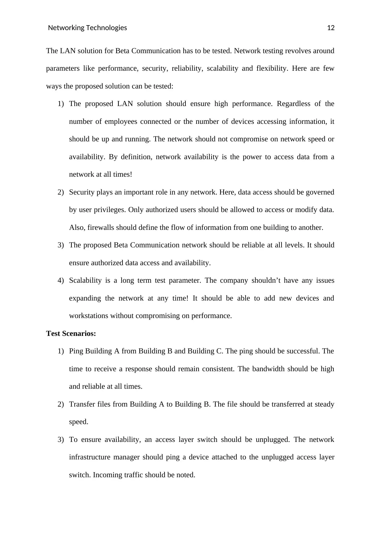
This report details the design and implementation of a Local Area Network (LAN) for Beta Communications, addressing the company's requirements across three buildings. The solution proposes a hierarchical network architecture, with Building C acting as the central hub for servers and network management. It outlines the use of Ethernet cabling for connectivity, multiple distribution switches, and access layer switches in each building. The report covers the design of distribution and access layers, including the configuration of routing protocols and network devices. The implementation section involves the simulation of the network using a software, demonstrating the connection of nodes, traffic sources, and the use of routers. The report further addresses network testing, covering performance, security, reliability, and scalability, along with various test scenarios. The report includes steps for implementing the LAN network, configuring switches, wiring, routing protocols, and firewall settings. The report also includes the router configuration, subnetting, and device configurations, and the process of the data center core router devices. The report concludes with a testing phase to validate the network's functionality and meet user requirements.

Networking Technologies 1
Networking Technologies
Student's Name:
Instructor's Name:
Date:
Networking Technologies
Student's Name:
Instructor's Name:
Date:
Paraphrase This Document
Need a fresh take? Get an instant paraphrase of this document with our AI Paraphraser

Networking Technologies 2
Task 3
A primitive LAN layout for Beta Communications network requirement would be as follows:
With the help of this network architecture, Beta Communication will not have any problems
expanding to remote locations too. The Building backbone can be broken into smaller
segments. According to current business functionalities, Beta Communications has broken
down tasks to three different buildings. It would be ideal to carry all important resources in a
single building and channel to the other buildings. Ideally, the building (C) with the network
infrastructure manager and technical teams should act as the central block. Servers, hardware
resources and software solutions must be deployed at this building (C). Employees located in
the other buildings can accept data from building (C). Such an architecture will make sure
Beta Communication performs all its operations in a secure and resilient manner.
Building (C) that acts as the core should be further broken into several segments. With proper
branching, individual modules can be accessed and maintained without compromising on the

Networking Technologies 3
overall quality of the network. The network at building C should have multiple distribution
switches.
Connection between building A, B and C can be established using access layer switches.
These switches can be spread across different buildings, irrespective of their location. The
switches are connected using Ethernet cables. The Ethernet cables are responsible for
transferring data from one location to another. Ethernet cabling will be useful when Beta
Communication wants to expand. The cables are known for its high performance and reliable
nature. They can handle huge performance goals without any problems. That means, Beta
Communication can attach many more nodes and not worry about speed, response rate,
turnaround time or safety. Ethernet cabling promises high bandwidth for Beta
Communication. There are special, fine-tuned protocols at Ethernet cabling level to ensure
data communication happens without any compromises. For instance, Beta Communication
can use 10-Gigabit uplink connectivity. This technique makes sure performance and
flexibility is achieved. Ethernet cabling and protocols form a part of Layer 2.
Benefits of using this multiple distribution layer architecture:
1) Nodes will be connected in a structured fashion.
2) It will be easier to find and remove faulty nodes.
3) It will be easier to maintain the overall network, without compromising on
performance.
4) It will be easier to add new nodes to the overall system.
Designing the Distribution Layer
⊘ This is a preview!⊘
Do you want full access?
Subscribe today to unlock all pages.

Trusted by 1+ million students worldwide

Networking Technologies 4
The distribution layer is responsible for aggregating all the access layer switches. It is
necessary to design the overall architecture of the distribution layer, before developing the
access layer. The distribution layer works across the three buildings. It is a medium to
connect the access layer switches. According to the proposed problem statement, Beta
Communication functions across three different buildings. The distribution layer is
responsible for connecting all access layer switches that are present in a particular building.
Later, the distribution layers can be connected together. The distribution layer plays an
integral role in this design. It acts as a boundary between layer 2 and 3 protocols.
Layer 2 is responsible for handling the spanning tree protocols. These protocols are necessary
to identify the route each packet in the network would take. The spanning tree protocols make
sure packets take the shortest and best possible route. There are several different types of
spanning tree protocols. Beta Communication has a network that is restricted to three
buildings that are closely located. A simple spanning tree protocol will be sufficient to ensure
quick and reliable communication. Moving on, the spanning tree protocolhandles all faults in
layer 2.
Layer 3 is responsible for holding information about the IP routing tables. The proposed
network design needs very few IP routing tables. These tables make sure packets are sent to
the right network gateway. With fewer number of routing tables, the process of
troubleshooting errors and recovering from faults becomes easier. The IP tables carry
information about sources and potential destinations. Packets transferred from one building to
another should go through the routing tables in Layer 3.
Designing the Access Layer
Paraphrase This Document
Need a fresh take? Get an instant paraphrase of this document with our AI Paraphraser

Networking Technologies 5
Once the multiple distribution layer is established, the individual access layers for each
building should be designed. The access layer can be deployed independently in each
building. The access layer can be independent from one another. Independent access layer
switches help in maintaining consistency and a stable network. Anyone who has access to
these switches will be able to transfer and receive data. Conversely, the access layer switches
can be protected using power firewalls. These firewalls can be configured from a single
interface that is maintained in Building C – the core! Access layer switches are responsible
for connecting network hardware devices. It acts as an interface that allows various devices
like standalone computers, IP phones and wireless access points to be connected. However,
access layer switches are destined to function in a specific building. Access layer switches in
each building can be connected together. This forms a complete LAN network for Beta
Communications.
Design Stages
To implement this LAN network, Beta communication should follow these stages:
1) The platform over which the network would be established has to be configured.
2) The LAN switches (both distribution layer and access layer switches) should be
configured. These switches should be configured with universal settings.
3) Wires that flow between the buildings should be configured. These wires should be
configured in line with the universal settings. The wires are important, since they
transfer and receive data! All firewall settings are dependent on the way these wires
are configured.
4) The unicast routing protocols should be configured.
5) The multicast routing protocols should be configured.

Networking Technologies 6
6) The distribution layer should be configured.
7) The access layer switches in each building should be configured.
8) The access layer switches in each building should be connected together.
9) The connected access layer switches should be linked to the distribution layer.
10) The WAN router for this network should be configured and shared across the LAN
core.
11) Firewall configuration has to be done to ensure safe and secure communication
between buildings.
12) Users should be registered and appropriate username & passwords should be
generated.
Routing in the Beta Communication Network
In Beta Communication, a switch is used to connect two or more devices. It is necessary for
exchange of information or data within the connected systems. The switches are then linked
to the router. The router is responsible for positioning and direction of web traffic. The router
configuration of Beta Communication will be as follows:
1) Navigate to Network Configuration, and click on “LAN setup”
2) Enter the IP address of the router
3) Enter the Domain name of the router
4) The starting and ending IP addresses are mentioned. For example, subnet 1 has a host
range between 200.168.0.1 – 200.168.0.14. Routers that handle traffic in this subnet
will be assigned the previous range. Likewise, Routers in subnet 2 will manage a host
range of 200.168.0.17 to 200.168.0.30. According to current design, here is a table to
show how the class range will be for each router.
⊘ This is a preview!⊘
Do you want full access?
Subscribe today to unlock all pages.

Trusted by 1+ million students worldwide

Networking Technologies 7
Router – subnet id Host Range
Router in subnet 1 200.168.0.1 – 200.168.0.14
Router in subnet 2 200.168.0.17 – 200.168.0.30
Router in subnet 3 200.168.0.33 – 200.168.0.46
Router in subnet 4 200.168.0.49 – 200.168.0.50
Router in subnet 5 200.168.0.53 – 200.168.0.54
Router in subnet 6 200.168.0.57 – 200.168.0.58
5) A Lease time is generated for clients
6) A DNS Proxy is enabled for the clients
7) Once the above steps are completed, the LAN router settings are saved.
Data Center Core Router Devices
Currently, Beta Communication is focusing on three separate buildings. Network managers at
Beta communication build data center networks with separate core router pairs. These routers
are connected to external networks and user access networks through firewalls. By choosing a
separate router, operational and capital expenses will be high, but the final network will be
extremely efficient.
The routers are a part of Layer 3 component. Routing between subnets ensures high data
security.
Paraphrase This Document
Need a fresh take? Get an instant paraphrase of this document with our AI Paraphraser

Networking Technologies 8
Task 4
4.1 – Implement a network systems based on the proposed design. You are required to
use means of simulation software, establish a network according to the design in task 3
# To be able to use nam, we should Create a nam trace datafile. set namfile [open
results/versuch1.nam w]
$ns namtrace-all $namfile
# After that, we should create the nodes
{ set node($i) [$ns node]}
$ns run
# After that, we should connect the nodes with each other
$ns duplex-link $node(0) $node(1) 1.0Mb 20.0ms DropTail
$ns duplex-link $node(0) $node(2) 1.0Mb 20.0ms DropTail
$ns duplex-link $node(1) $node(2) 1.0Mb 20.0ms DropTail
$ns run

Networking Technologies 9
# After that, we have to create the
Connection for one of the Core nodes in the building
$agents set agent(0) [new Agent/UDP]
$ns attach-agent $node(1) $agent(0)
$agent(0) set fid_ 6
$ns color 6 "red„
set sink(0) [new Agent/Null]
$ns attach-agent $node(1) $sink(0)
$ns connect $agent(0) $sink(0)
# After that, we have to create traffic source and add it to the
agent set traffic_source(0) [new Application/Traffic/CBR]
$traffic_source(0) set interval_ 0.001950
$traffic_source(0) set paketSize_ 230
$traffic_source(0) attach-agent $agent(0)
# Now, we have to schedule starting and stopping the traffic source
$ns at 3.0 "$traffic_source(0) start„
$ns at 100.0 "$traffic_source(0) stop„
⊘ This is a preview!⊘
Do you want full access?
Subscribe today to unlock all pages.

Trusted by 1+ million students worldwide

Networking Technologies 10
# Now, we have to start the finish
procedure proc finish {} {
global ns namfile $ns flush-trace close $namfile
exec nam results/versuch1.nam & exit 0
}
# After that, we have to schedule the stop
procedure $ns at 110.000000 "finish"
To Handle Mobility Between Nodes
# Create simulator instance
set ns_ [new Simulator]
# Create nam and trace files
set tracefd [open out.tr w]
set namtrace [open out.nam w]
Paraphrase This Document
Need a fresh take? Get an instant paraphrase of this document with our AI Paraphraser

Networking Technologies 11
$ns_ trace-all $tracefd
$ns_ namtrace-all-wireless $namtrace $opt(x) $opt(y)
# Create a file to record the lost packets for UDP
set LostPackets [open UDPlost.tr w]
Set up the hierarchical routing
$ns_ node-config -addressType hierarchical
AddrParams set domain_num_ 7 lappend
cluster_num 1 1 1 1 1 1 1 AddrParams
set cluster_num_ $cluster_numlappendeilastlevel 2 2 1 1 1 1 1 AddrParams
set nodes_num_ $eilastlevel
4.2. Test network systems to meet user requirements. Your testing includes functionality
of the network to ensure that your developed network will operate seamlessly in a
physical environment so that it can satisfy user requirements.

Networking Technologies 12
The LAN solution for Beta Communication has to be tested. Network testing revolves around
parameters like performance, security, reliability, scalability and flexibility. Here are few
ways the proposed solution can be tested:
1) The proposed LAN solution should ensure high performance. Regardless of the
number of employees connected or the number of devices accessing information, it
should be up and running. The network should not compromise on network speed or
availability. By definition, network availability is the power to access data from a
network at all times!
2) Security plays an important role in any network. Here, data access should be governed
by user privileges. Only authorized users should be allowed to access or modify data.
Also, firewalls should define the flow of information from one building to another.
3) The proposed Beta Communication network should be reliable at all levels. It should
ensure authorized data access and availability.
4) Scalability is a long term test parameter. The company shouldn’t have any issues
expanding the network at any time! It should be able to add new devices and
workstations without compromising on performance.
Test Scenarios:
1) Ping Building A from Building B and Building C. The ping should be successful. The
time to receive a response should remain consistent. The bandwidth should be high
and reliable at all times.
2) Transfer files from Building A to Building B. The file should be transferred at steady
speed.
3) To ensure availability, an access layer switch should be unplugged. The network
infrastructure manager should ping a device attached to the unplugged access layer
switch. Incoming traffic should be noted.
⊘ This is a preview!⊘
Do you want full access?
Subscribe today to unlock all pages.

Trusted by 1+ million students worldwide
1 out of 16
Related Documents

Your All-in-One AI-Powered Toolkit for Academic Success.
+13062052269
info@desklib.com
Available 24*7 on WhatsApp / Email
Unlock your academic potential
Copyright © 2020–2025 A2Z Services. All Rights Reserved. Developed and managed by ZUCOL.