CCNA Assessment 1: Western Mining Network Rectification Solution

Verified

Added on  2023/04/11

|22
|1517
|52
Practical Assignment
AI Summary
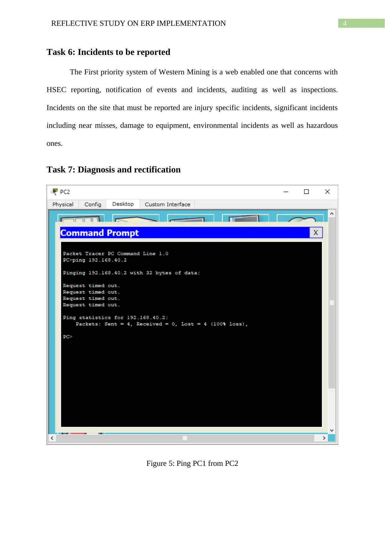
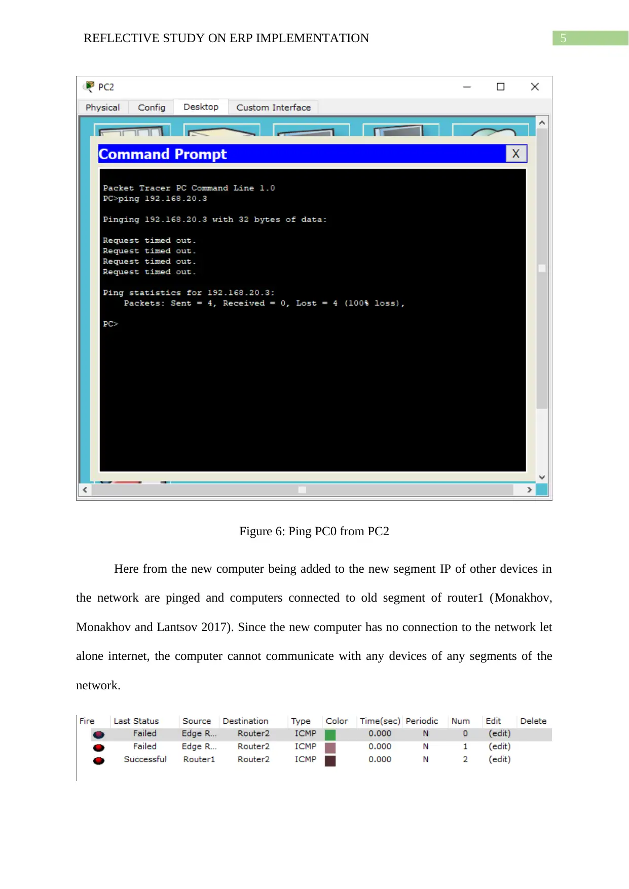
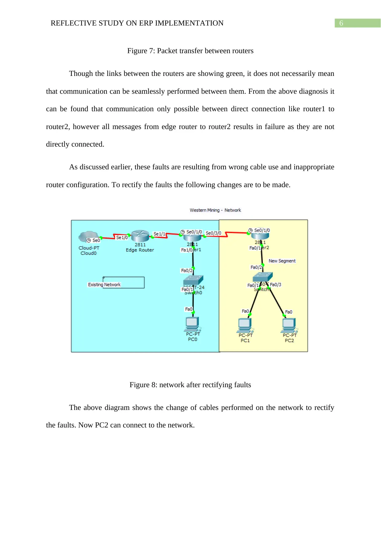
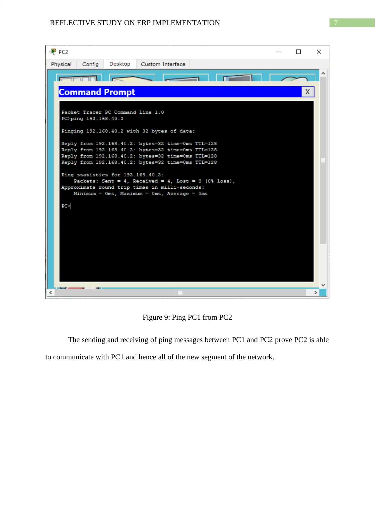
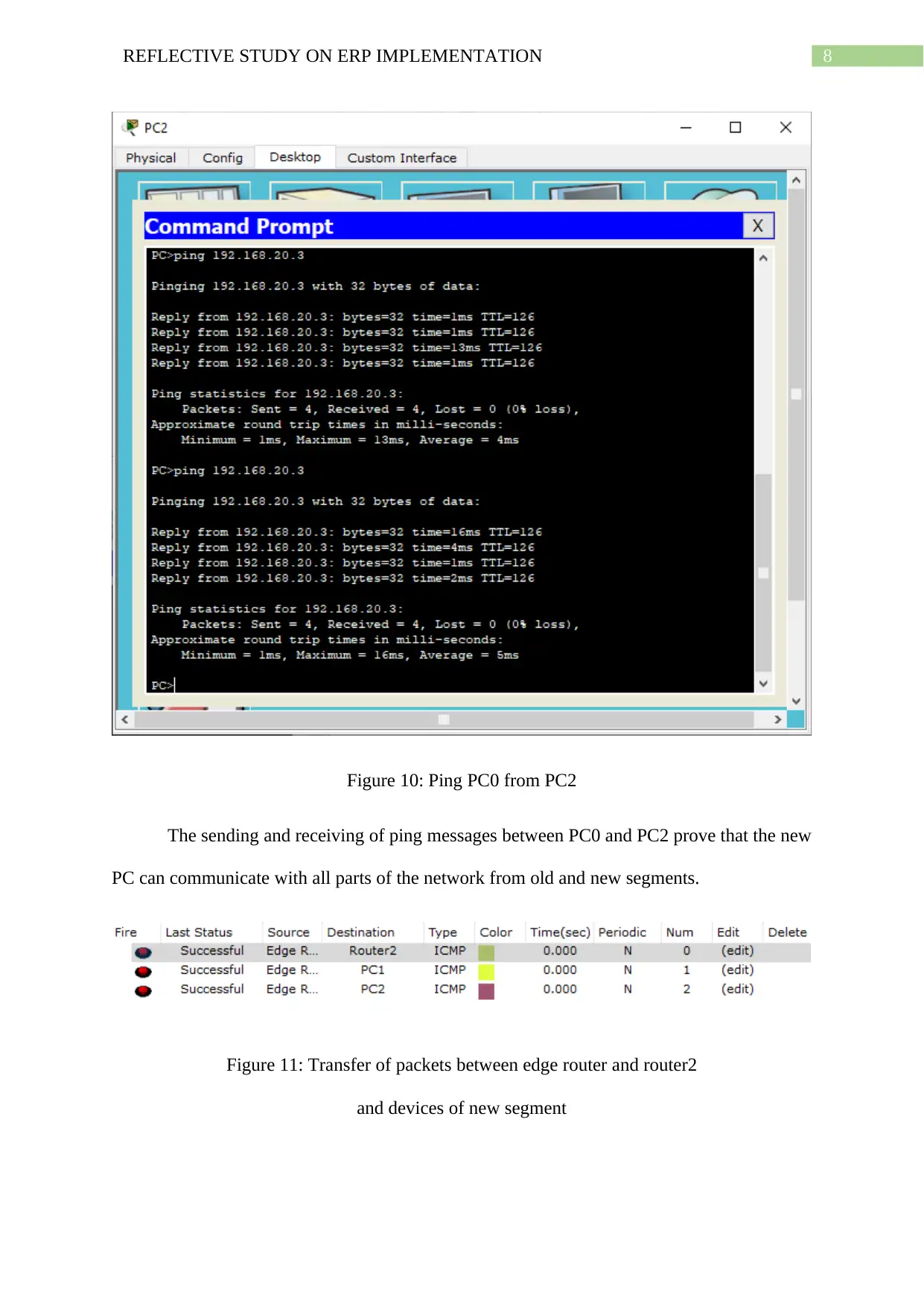
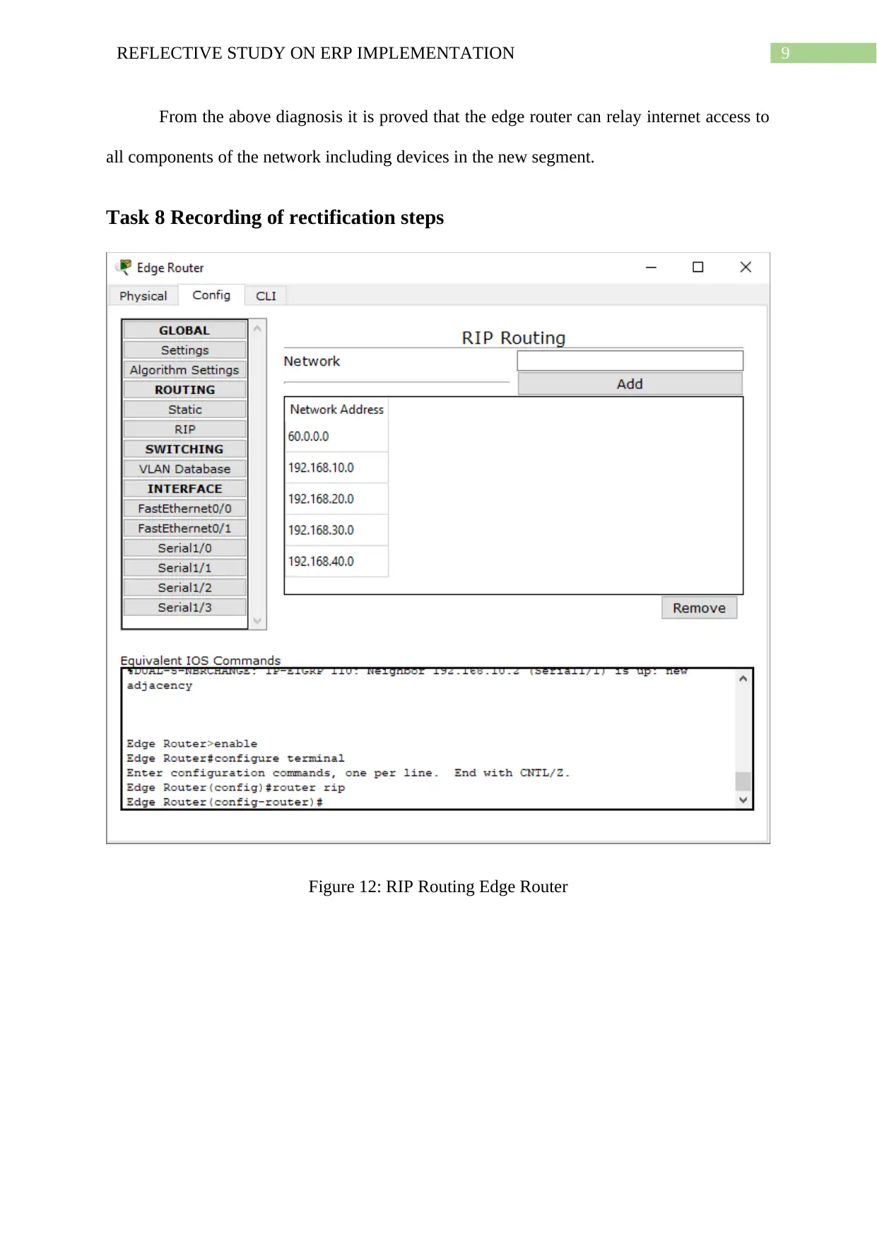
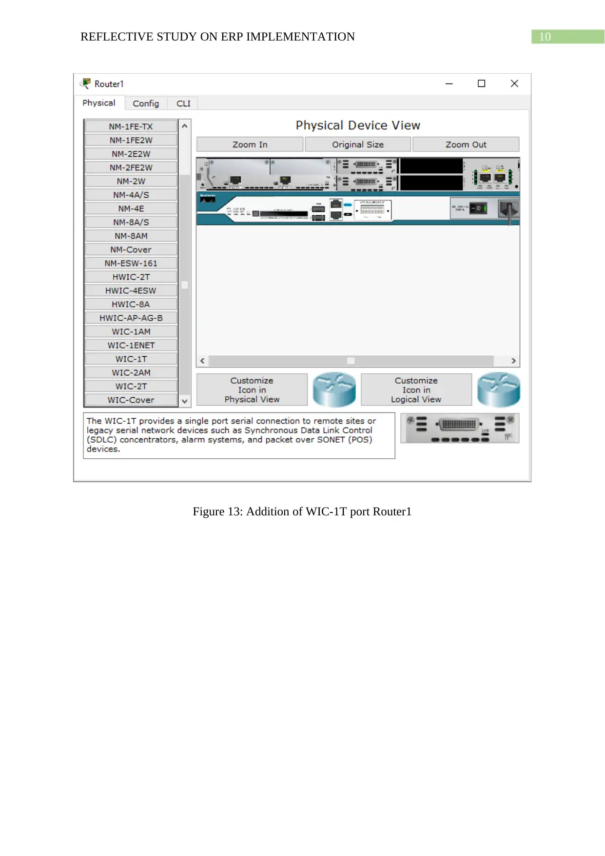
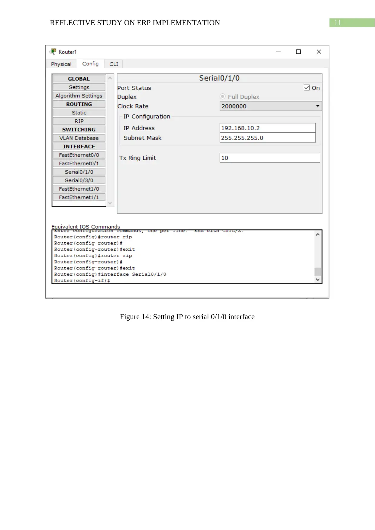
This document provides a detailed reflection on the process of rectifying network faults in a simulated environment, specifically focusing on a case study involving Western Mining. The assignment, designed as part of a CCNA assessment, requires the identification of faults, which include incorrect cabling and improper router configuration, and implementing the appropriate solutions. The solution involves the use of Cisco Packet Tracer for diagnosis and the physical modification of network cables, including the use of serial and straight-through cables, to ensure proper communication between routers and connected devices. The report outlines the steps taken, including the configuration of RIP routing, setting IP addresses for interfaces, and verifying network connectivity through ping tests. The document also covers relevant regulations, access procedures, and the costs associated with the rectification work, providing a comprehensive overview of the troubleshooting and implementation process.
Document Page
Running head: WESTERN MINING NETWORK RECTIFICATION
Western Mining Network Rectification
Amanvir Kaur
Name of the University
Author Note
tabler-icon-diamond-filled.svg

Paraphrase This Document

Need a fresh take? Get an instant paraphrase of this document with our AI Paraphraser
Document Page
1REFLECTIVE STUDY ON ERP IMPLEMENTATION
Task 2: Nature of the fault and solution
The service required by Western Mining from Pacific IT includes support plans for
Break / Fix with Corporate Premium on site Support involving response time of two (2)
hours. Here apart from the new computer added to the network of the new router router2,
router 1 and router 2 also is connected with the help of crossover cables (Novick and
Lombardi 2015). These are to be replaced and the billing for this service is done separately.
Figure 3: Western Mining network with faults
All the three routers need to be connected by using serial cables in order to facilitate
inter router data communications through Routing Information Protocol (RIP) routing (Al-
Ani and Al-Ani 2018). All computers and clients in any network, old or new must be
connected through straight through LAN cables to obtain network access (Islam 2016).
Document Page
2REFLECTIVE STUDY ON ERP IMPLEMENTATION
Figure 4: Western Mining network with faults rectified
Here to set up routing, the routes a packet should take in navigating through the
network get defined like the network 192.168.20.0 of router 1 is accessible from edge router
by network 192.168.10.2 through which router1 obtains network from the edge router
(Chiesa et al. 2016). Similarly access of network 192.168.40.0 through network 192.168.30.1
by edge router via router1 (Lemeshko et al. 2016). To enable communications between all
three routers via one another, all the networks are added in RIP section of the routers.
Task 3: Regulations and code of practices
The primary set of regulations and practices for the work done in rectifying faults is
the AS-NZS 3000-2007 which deals with separation of low voltage cables and
Telecommunications cables based in installation and cabling for commercial and work
premises (Horner and Wilmshurst 2016). This can be found in the section 3.9.8.4 (c) page
147. To rectify the faults in the network of Western Mining, the network cabling had to be
changed from the edge router near old segment of the network and all the way to the new
Document Page
3REFLECTIVE STUDY ON ERP IMPLEMENTATION
segment of the network. Additionally, cable for one of the newly added PC needed to be
changed too. This required physically installing cable specific ports and connecting the
cables. Here the different types of cable like serial cable has their own standards as are
straight ethernet cables. The specifications thus required to be verified.
Task 4: Steps to arrange access
Olympic Dam Security always controls and monitors access to the mining site of
Western Mining (Shao 2017). As per Olympic dam procedures and polies they reserve the
right of removing any person from the site. For access the following are required:
1. Getting Secure ID cards issued
2. Access systems to the site approved.
3. Obtaining appropriate designation for nature and role of work
Hence inductions of contractor personnel must be completed, if access to the mining site
is to be granted.
Task 5: Tools for diagnosing faults
The fault identified with the network is wrong cabling and inadequate configuration
of the network. As a result, such faults can be identified with the help of network simulation
and diagnostic software applications like cisco packet tracer (Archana 2015). If the faults are
related to configuration only no additional equipment is required. Here the faults identified
are tied to configuration and wrong cable use and so the different cables will be needed.
These are serial cables and ports for connecting router1 with edge router and router2 with
router1.
tabler-icon-diamond-filled.svg

Paraphrase This Document

Need a fresh take? Get an instant paraphrase of this document with our AI Paraphraser
Document Page
4REFLECTIVE STUDY ON ERP IMPLEMENTATION
Task 6: Incidents to be reported
The First priority system of Western Mining is a web enabled one that concerns with
HSEC reporting, notification of events and incidents, auditing as well as inspections.
Incidents on the site that must be reported are injury specific incidents, significant incidents
including near misses, damage to equipment, environmental incidents as well as hazardous
ones.
Task 7: Diagnosis and rectification
Figure 5: Ping PC1 from PC2
Document Page
5REFLECTIVE STUDY ON ERP IMPLEMENTATION
Figure 6: Ping PC0 from PC2
Here from the new computer being added to the new segment IP of other devices in
the network are pinged and computers connected to old segment of router1 (Monakhov,
Monakhov and Lantsov 2017). Since the new computer has no connection to the network let
alone internet, the computer cannot communicate with any devices of any segments of the
network.
Document Page
6REFLECTIVE STUDY ON ERP IMPLEMENTATION
Figure 7: Packet transfer between routers
Though the links between the routers are showing green, it does not necessarily mean
that communication can be seamlessly performed between them. From the above diagnosis it
can be found that communication only possible between direct connection like router1 to
router2, however all messages from edge router to router2 results in failure as they are not
directly connected.
As discussed earlier, these faults are resulting from wrong cable use and inappropriate
router configuration. To rectify the faults the following changes are to be made.
Figure 8: network after rectifying faults
The above diagram shows the change of cables performed on the network to rectify
the faults. Now PC2 can connect to the network.
tabler-icon-diamond-filled.svg

Paraphrase This Document

Need a fresh take? Get an instant paraphrase of this document with our AI Paraphraser
Document Page
7REFLECTIVE STUDY ON ERP IMPLEMENTATION
Figure 9: Ping PC1 from PC2
The sending and receiving of ping messages between PC1 and PC2 prove PC2 is able
to communicate with PC1 and hence all of the new segment of the network.
Document Page
8REFLECTIVE STUDY ON ERP IMPLEMENTATION
Figure 10: Ping PC0 from PC2
The sending and receiving of ping messages between PC0 and PC2 prove that the new
PC can communicate with all parts of the network from old and new segments.
Figure 11: Transfer of packets between edge router and router2
and devices of new segment
Document Page
9REFLECTIVE STUDY ON ERP IMPLEMENTATION
From the above diagnosis it is proved that the edge router can relay internet access to
all components of the network including devices in the new segment.
Task 8 Recording of rectification steps
Figure 12: RIP Routing Edge Router
tabler-icon-diamond-filled.svg

Paraphrase This Document

Need a fresh take? Get an instant paraphrase of this document with our AI Paraphraser
Document Page
10REFLECTIVE STUDY ON ERP IMPLEMENTATION
Figure 13: Addition of WIC-1T port Router1
Document Page
11REFLECTIVE STUDY ON ERP IMPLEMENTATION
Figure 14: Setting IP to serial 0/1/0 interface
chevron_up_icon
1 out of 22
circle_padding
hide_on_mobile
zoom_out_icon
[object Object]