Microwave Link Analysis and Passive Repeaters - Networking Concepts

Verified

Added on  2022/11/11

|6
|516
|351
Homework Assignment
AI Summary
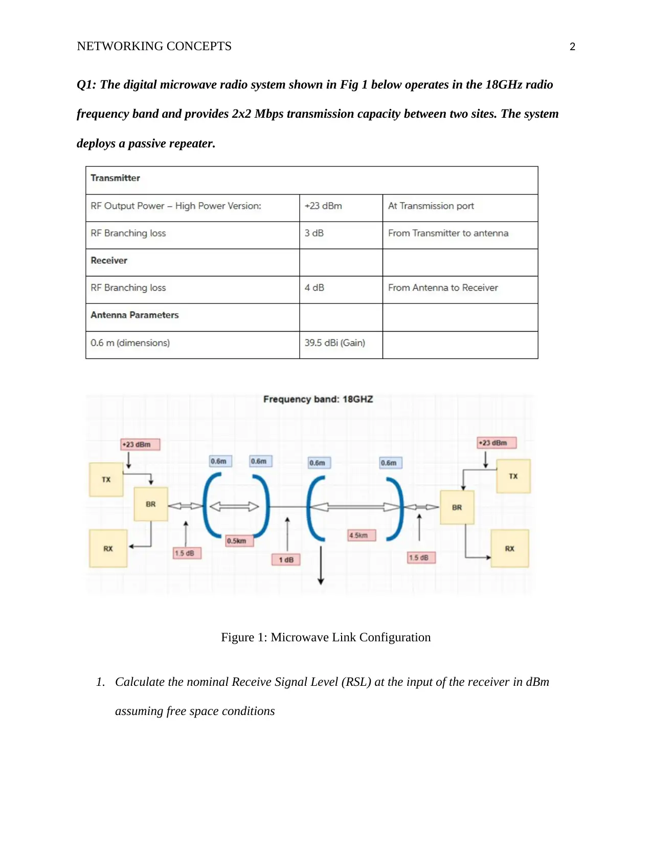
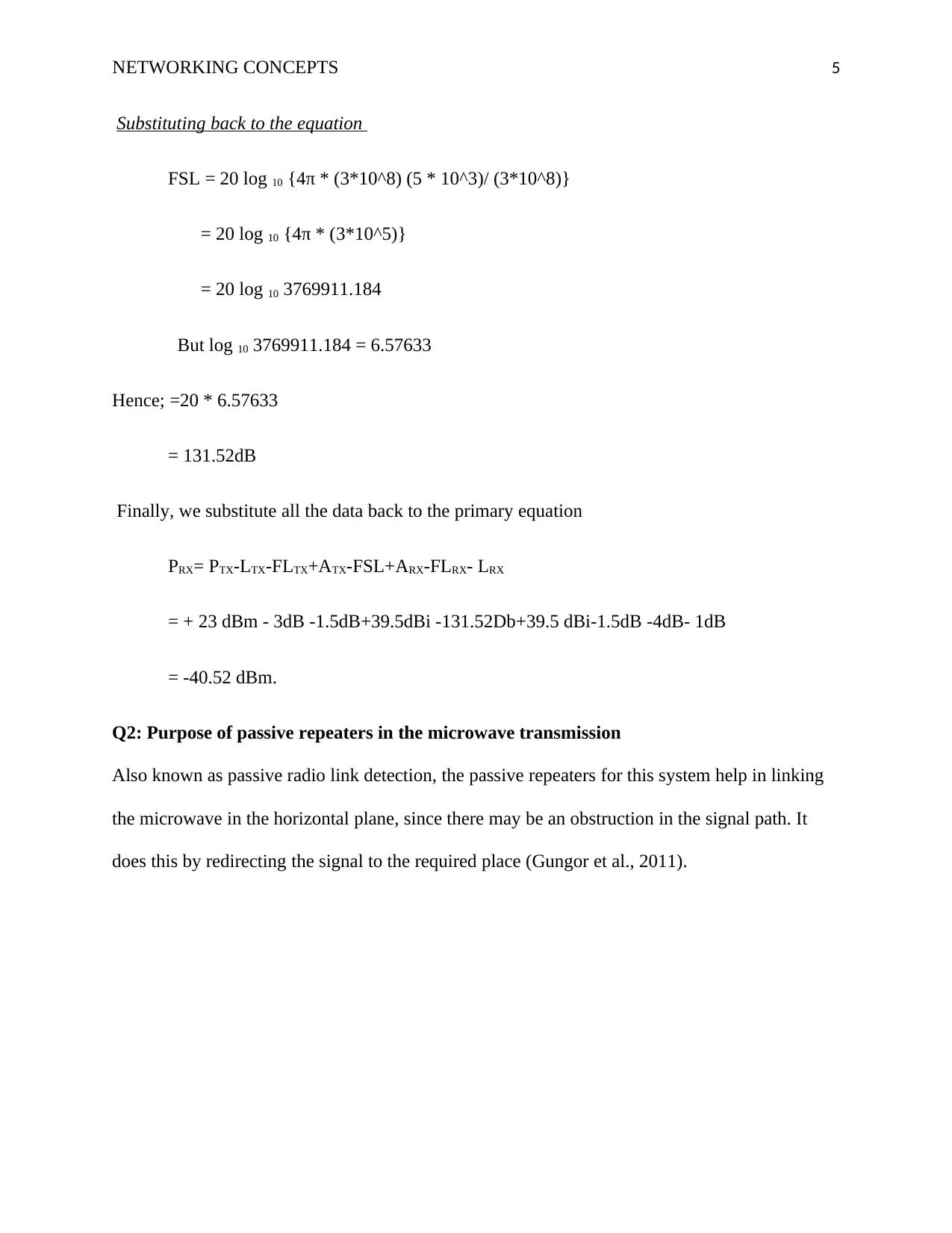
This document provides a detailed solution to a networking concepts assignment. The assignment focuses on analyzing a digital microwave radio system operating in the 18GHz radio frequency band. The solution includes the calculation of the nominal Receive Signal Level (RSL) at the receiver input under free space conditions, using the provided parameters such as transmitter power, losses, and antenna gains. The free space loss is calculated, and the link budget is determined to find the RSL. Furthermore, the document explains the purpose of passive repeaters in microwave transmission systems, highlighting their role in redirecting signals to overcome obstructions. The solution includes relevant references to support the analysis and calculations.
Document Page
Running head: NETWORKING CONCEPTS 1
Networking Concepts
Name of Student
Institution Affiliation
tabler-icon-diamond-filled.svg

Secure Best Marks with AI Grader

Need help grading? Try our AI Grader for instant feedback on your assignments.
Document Page
NETWORKING CONCEPTS 2
Q1: The digital microwave radio system shown in Fig 1 below operates in the 18GHz radio
frequency band and provides 2x2 Mbps transmission capacity between two sites. The system
deploys a passive repeater.
Figure 1: Microwave Link Configuration
1. Calculate the nominal Receive Signal Level (RSL) at the input of the receiver in dBm
assuming free space conditions
Document Page
NETWORKING CONCEPTS 3
Solution
Unfaded conditions:
In these conditions, the link budget is determined by the formula
PRX= PTX-LTX-FLTX+ATX-FSL+ARX-FLRX- LRX
Where PRX= Unfaded Nominal Receiver Level in dBm
PTX = output of transmitter power in dBm
LTX =branching loses in the transmitter
FLTX = transmitter feeder loses of the waveguide or cable in dB
ATX = the antennae gains in dBi (Rathnayaka et al., 2011).
FSL = the free space loses
ARX = the antenna gains in dBi
FLRX =receiver feeder loses of the waveguide or cable in dB
LRX =receiver branching loses
The provided parameters are
PTX = + 23 dBm
LTX = 3dB
FLTX = 1.5dB
ATX = 39.5dBi
Document Page
NETWORKING CONCEPTS 4
FSL =?
ARX = 39.5 dBi
FLRX = 1.5dB
LRX = 4dB
Other Loses= 1dB
f = 18GHz= (18 * 10^9) Hz
D= (4.5 + 0.5) Km
= 5km
We will first determine the value of FSL.
FSL=
WHERE D= 5km
= 5 * 10^3
f= 18*10^9
c= 3*10^8
tabler-icon-diamond-filled.svg

Secure Best Marks with AI Grader

Need help grading? Try our AI Grader for instant feedback on your assignments.
Document Page
NETWORKING CONCEPTS 5
Substituting back to the equation
FSL = 20 log 10 {4π * (3*10^8) (5 * 10^3)/ (3*10^8)}
= 20 log 10 {4π * (3*10^5)}
= 20 log 10 3769911.184
But log 10 3769911.184 = 6.57633
Hence; =20 * 6.57633
= 131.52dB
Finally, we substitute all the data back to the primary equation
PRX= PTX-LTX-FLTX+ATX-FSL+ARX-FLRX- LRX
= + 23 dBm - 3dB -1.5dB+39.5dBi -131.52Db+39.5 dBi-1.5dB -4dB- 1dB
= -40.52 dBm.
Q2: Purpose of passive repeaters in the microwave transmission
Also known as passive radio link detection, the passive repeaters for this system help in linking
the microwave in the horizontal plane, since there may be an obstruction in the signal path. It
does this by redirecting the signal to the required place (Gungor et al., 2011).
Document Page
NETWORKING CONCEPTS 6
References
Gungor, V. C., Sahin, D., Kocak, T., Ergut, S., Buccella, C., Cecati, C., & Hancke, G. P. (2011).
Smart grid technologies: Communication technologies and standards. IEEE transactions
on Industrial informatics, 7(4), 529-539.
Rathnayaka, A. D., Potdar, V. M., & Kuruppu, S. J. (2011, May). Evaluation of wireless home
automation technologies. In 5th IEEE International Conference on Digital Ecosystems
and Technologies (IEEE DEST 2011) (pp. 76-81). IEEE.
chevron_up_icon
1 out of 6
circle_padding
hide_on_mobile
zoom_out_icon
logo.png

Your All-in-One AI-Powered Toolkit for Academic Success.

Available 24*7 on WhatsApp / Email

[object Object]