Networking Models and IP Address Allocation Report - Advanced Digital
VerifiedAdded on 2022/10/11
|28
|2091
|12
Report
AI Summary
This report provides a detailed analysis of networking models and IP address allocation, focusing on the context of Advanced Digital Computing. It begins by introducing the OSI reference model, explaining its layers and their functions. The report then delves into the WAN network design of the company, illustrating the network architecture with a diagram and explaining the roles of routers and switches. A significant portion of the report is dedicated to IP addressing and subnetting, including IPv4 protocol, CIDR, and subnet calculations for different network segments. The report includes hands-on projects that demonstrate practical applications of IP addressing and subnetting. The report concludes by summarizing the key findings and emphasizing the importance of IP addressing in network setup and management.

Running head: NETWORKING MODELS AND IP ADDRESS ALLOCATION
Networking Models and IP Address Allocation
Name of the Student
Name of the University
Author Note
Networking Models and IP Address Allocation
Name of the Student
Name of the University
Author Note
Paraphrase This Document
Need a fresh take? Get an instant paraphrase of this document with our AI Paraphraser
1
NETWORKING MODELS AND IP ADDRESS ALLOCATION
Summary
IP addressing and subnet calculations play a crucial role in setting up any network. The study
details the addressing scheme and subnet calculation of one such network for Advanced
Digital Computing. Firstly, the report talks about the OSI reference model along with the
hardware and software layers involved. Then it presents the WAN network design of the
company and explains it. After that the report presents the IP addressing and subnetting
details and then ends with conclusions.
2
NETWORKING MODELS AND IP ADDRESS ALLOCATION
Table of Contents
Introduction................................................................................................................................3
Solution......................................................................................................................................3
OSI Reference Model.............................................................................................................3
Hands-On Projects.................................................................................................................5
Hands-On Project 2-3.........................................................................................................5
Hands-On Project 2-4.........................................................................................................7
Hands-On Project 2-5.......................................................................................................17
Network and IP Addressing.................................................................................................21
Network Design...............................................................................................................21
Subnets and IP Allocation....................................................................................................21
Conclusion................................................................................................................................25
References................................................................................................................................26
⊘ This is a preview!⊘
Do you want full access?
Subscribe today to unlock all pages.

Trusted by 1+ million students worldwide
3
NETWORKING MODELS AND IP ADDRESS ALLOCATION
Introduction
The report highlights the importance of IP addressing and subnet calculations in
setting up networks (Gilchrist, 2016). The study provides the addressing scheme and subnet
calculation of one such network for Advanced Digital Computing. The report begins by
talking about the OSI reference model along with the hardware and software layers involved.
Then it presents the WAN network design of the company and explains it. After that the
report presents the IP addressing and subnetting details and then ends with conclusions.
Solution
OSI Reference Model
The OSI model for networking from Open Systems Interconnection refers to the
conceptual model, the characteristics and standards of which define the functions of
communication in various computing and telecommunication systems without having to rely
on the internal structuring and underlying technologies (Zhao et al., 2018). That is the OSI
model aims to bring interoperability of different forms of communication systems with
standardized protocols. There are seven different layers of communication protocols defined
by the OSI reference model. These are:
Layer 1 or Physical layer concerns with transmitting and receiving of unordered data among
devices like routers, switches and various physical transmission media like ethernet cables
(Colin, Mathieu & Nakechbandi, 2016). Here the digital data bits get converted to electrical,
optical or even radio signals. The layer also defines the voltages, timings, data rates of
various physical connectors.
Layer 2 or Data Link layer concerns data transfer between one node and another through
links between two nodes that are directly connected. The layer serves in detection and
Paraphrase This Document
Need a fresh take? Get an instant paraphrase of this document with our AI Paraphraser
4
NETWORKING MODELS AND IP ADDRESS ALLOCATION
correction of errors. There can exist two sublayers as per IEEE 802. These are Medium
Access Control(MAC) and Logical Link Control(LLC).
Layer 3 or Network layer facilitates the process and functional needs for transfer of data of
varying lengths commonly called packets between one node and another among multiple
connected networks. A network serves as the medium for connecting several nodes.
The above discussed layers comprise the hardware layers of OSI model.
Layer 4 or Transport Layer ensures that quality of service is maintained while the data
transfer between the nodes occur. It uses segmentation, desegmentation, error control as also
flow control so as to assure the reliability of the links through which the data gets transmitted
(Aldosari, 2015). This is the heart of the OSI model.
The layers discussed below comprise the software layers of OSI model.
Layer 5 or Session layer is responsible for controlling dialogues among different computers.
It allows management, set up and graceful termination of connections between the remote as
well as the locally installed applications.
Layer 6 or Presentation sets up the context among entities of the application layer from
which the entities can use the various semantics once they start getting mapped by the
presentation services.
When mapping can be established, the presentation protocol data units or PDUs get
encapsulated in session PDUs and are passed along the stack of protocols.
Layer 7 or Application refers to that OSI layer which is closest to users of the systems of a
network. This means the user and the OSI application layer both actively interacts with the
concerned software tools and applications that form the components of the communication.
5
NETWORKING MODELS AND IP ADDRESS ALLOCATION
Internet layer of TCP/IP networking model concerns with logical transmission of data packets
over the internet in the same way OSI model’s network layer and hence these layers are
referred in exchangeable ways (Wollschlaeger, Sauter & Jasperneite, 2017). The name
Internet layer mainly comes from the protocols being used specifically IP or Internet
Protocol. The key functions are routing each data packet from their source to the respective
destination, independently through optimal routes.
Hands-On Projects
Hands-On Project 2-3
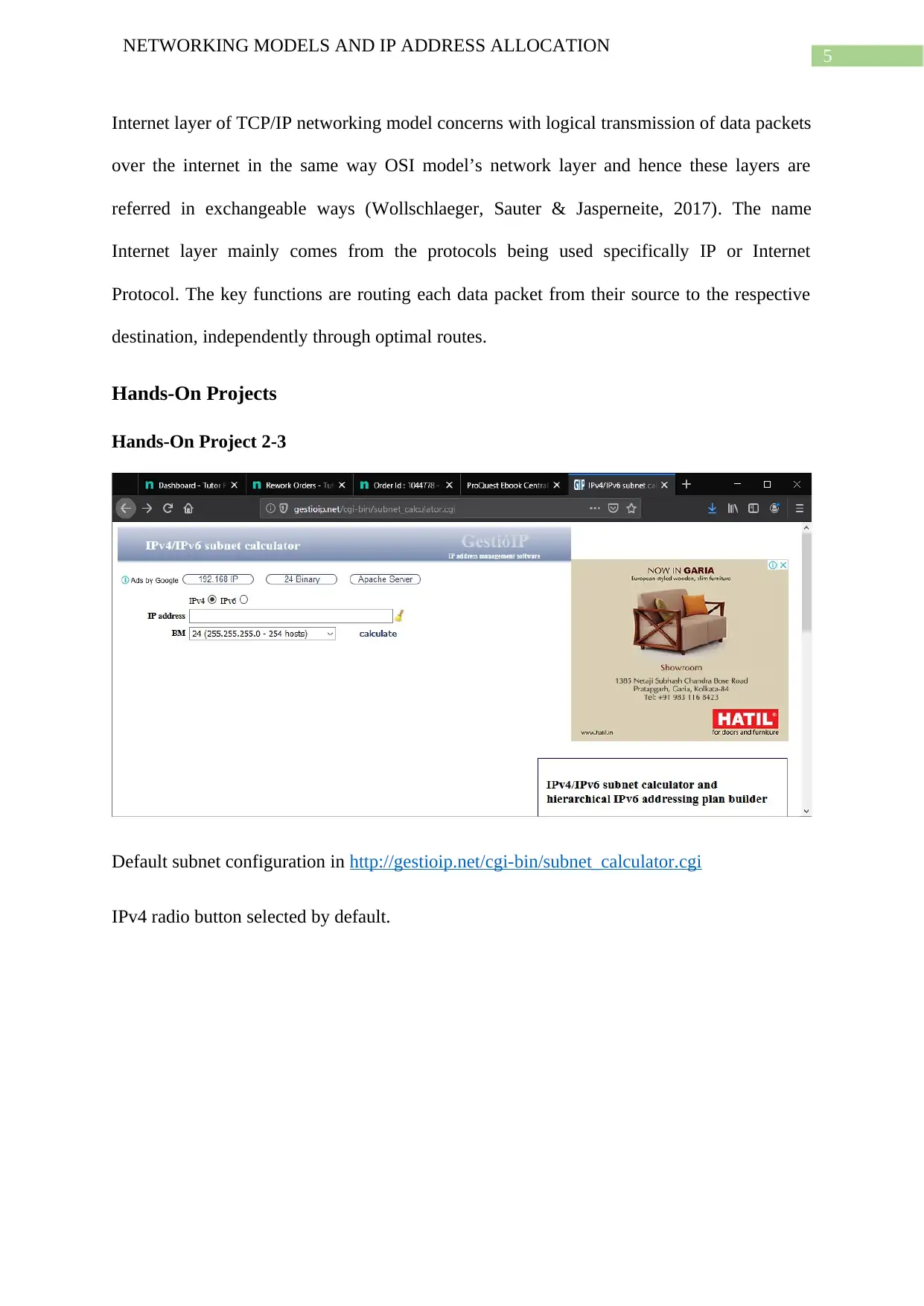
Default subnet configuration in http://gestioip.net/cgi-bin/subnet_calculator.cgi
IPv4 radio button selected by default.
⊘ This is a preview!⊘
Do you want full access?
Subscribe today to unlock all pages.

Trusted by 1+ million students worldwide
6
NETWORKING MODELS AND IP ADDRESS ALLOCATION
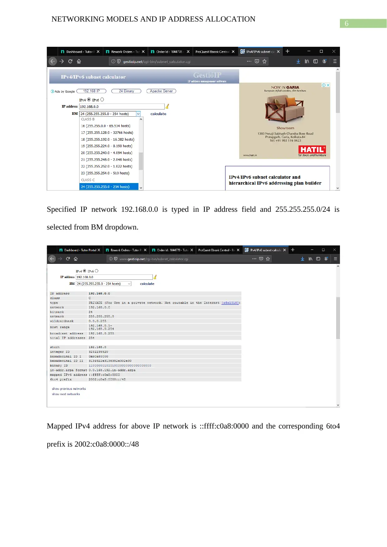
Specified IP network 192.168.0.0 is typed in IP address field and 255.255.255.0/24 is
selected from BM dropdown.
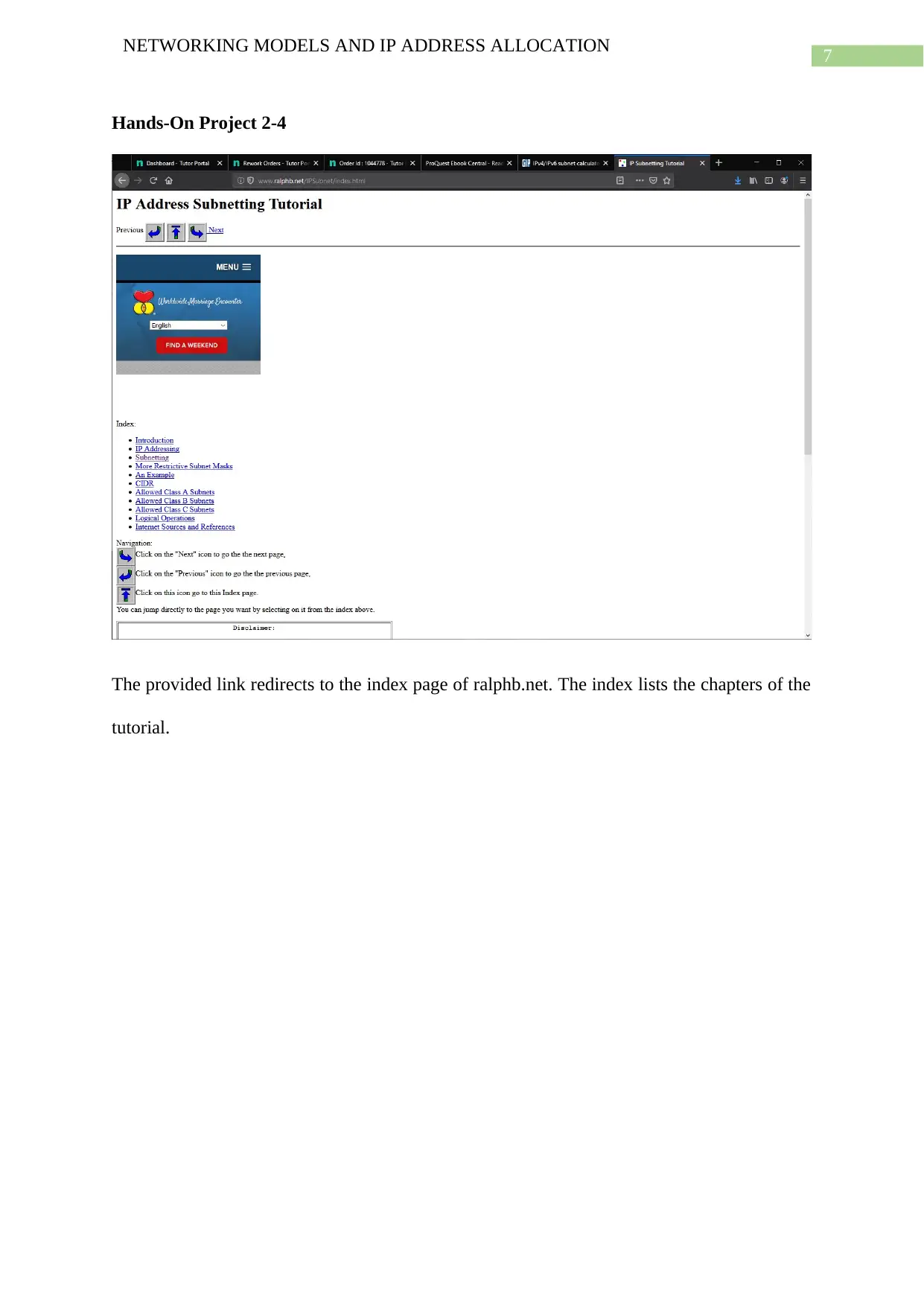
Mapped IPv4 address for above IP network is ::ffff:c0a8:0000 and the corresponding 6to4
prefix is 2002:c0a8:0000::/48
NETWORKING MODELS AND IP ADDRESS ALLOCATION
Specified IP network 192.168.0.0 is typed in IP address field and 255.255.255.0/24 is
selected from BM dropdown.
Mapped IPv4 address for above IP network is ::ffff:c0a8:0000 and the corresponding 6to4
prefix is 2002:c0a8:0000::/48
Paraphrase This Document
Need a fresh take? Get an instant paraphrase of this document with our AI Paraphraser
7
NETWORKING MODELS AND IP ADDRESS ALLOCATION
Hands-On Project 2-4
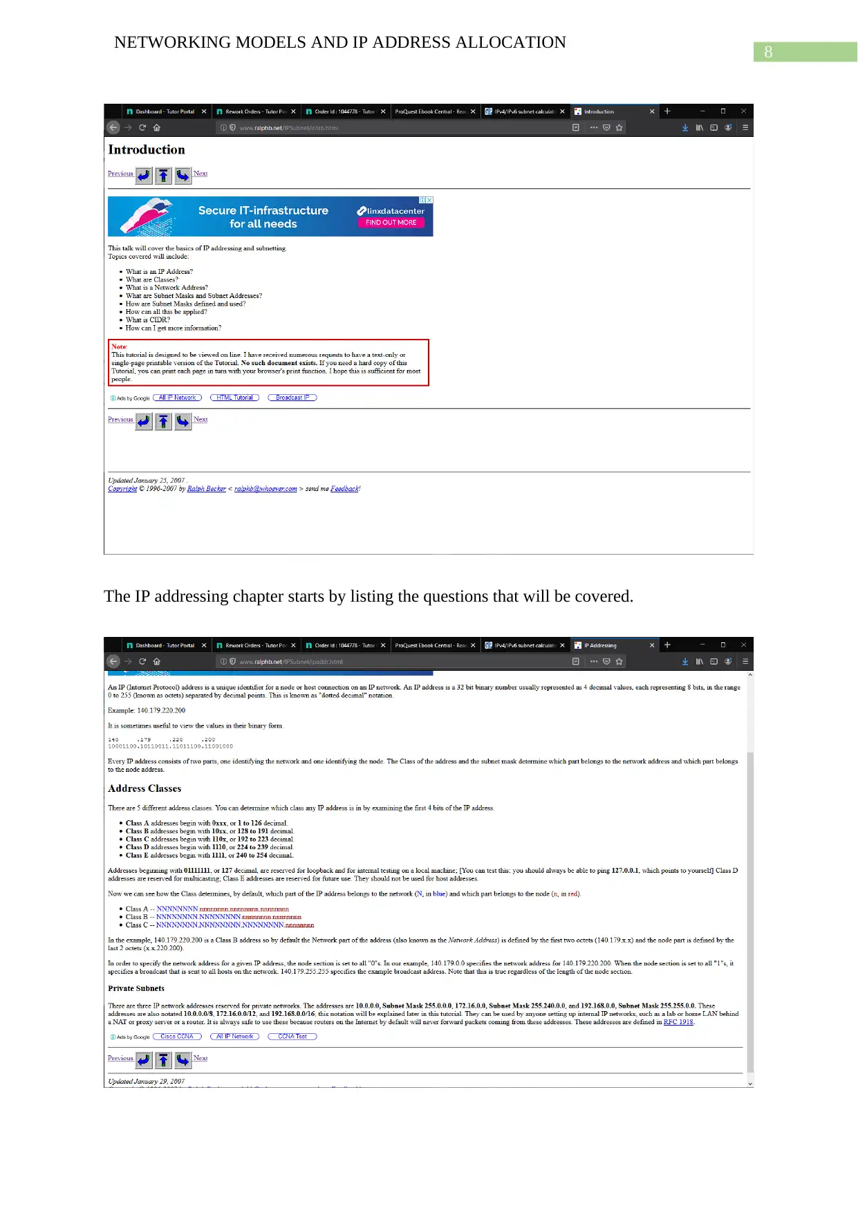
The provided link redirects to the index page of ralphb.net. The index lists the chapters of the
tutorial.
NETWORKING MODELS AND IP ADDRESS ALLOCATION
Hands-On Project 2-4
The provided link redirects to the index page of ralphb.net. The index lists the chapters of the
tutorial.
8
NETWORKING MODELS AND IP ADDRESS ALLOCATION
The IP addressing chapter starts by listing the questions that will be covered.
NETWORKING MODELS AND IP ADDRESS ALLOCATION
The IP addressing chapter starts by listing the questions that will be covered.
⊘ This is a preview!⊘
Do you want full access?
Subscribe today to unlock all pages.

Trusted by 1+ million students worldwide
9
NETWORKING MODELS AND IP ADDRESS ALLOCATION
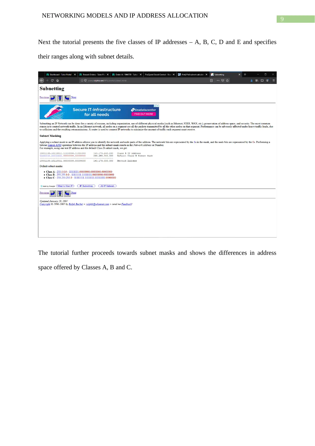
Next the tutorial presents the five classes of IP addresses – A, B, C, D and E and specifies
their ranges along with subnet details.
The tutorial further proceeds towards subnet masks and shows the differences in address
space offered by Classes A, B and C.
Paraphrase This Document
Need a fresh take? Get an instant paraphrase of this document with our AI Paraphraser
10
NETWORKING MODELS AND IP ADDRESS ALLOCATION
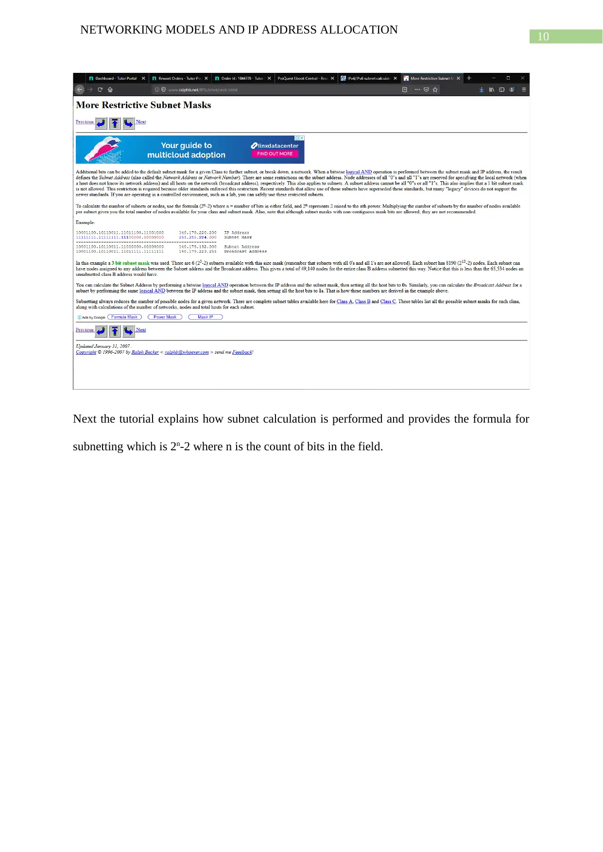
Next the tutorial explains how subnet calculation is performed and provides the formula for
subnetting which is 2n-2 where n is the count of bits in the field.
NETWORKING MODELS AND IP ADDRESS ALLOCATION
Next the tutorial explains how subnet calculation is performed and provides the formula for
subnetting which is 2n-2 where n is the count of bits in the field.
11
NETWORKING MODELS AND IP ADDRESS ALLOCATION
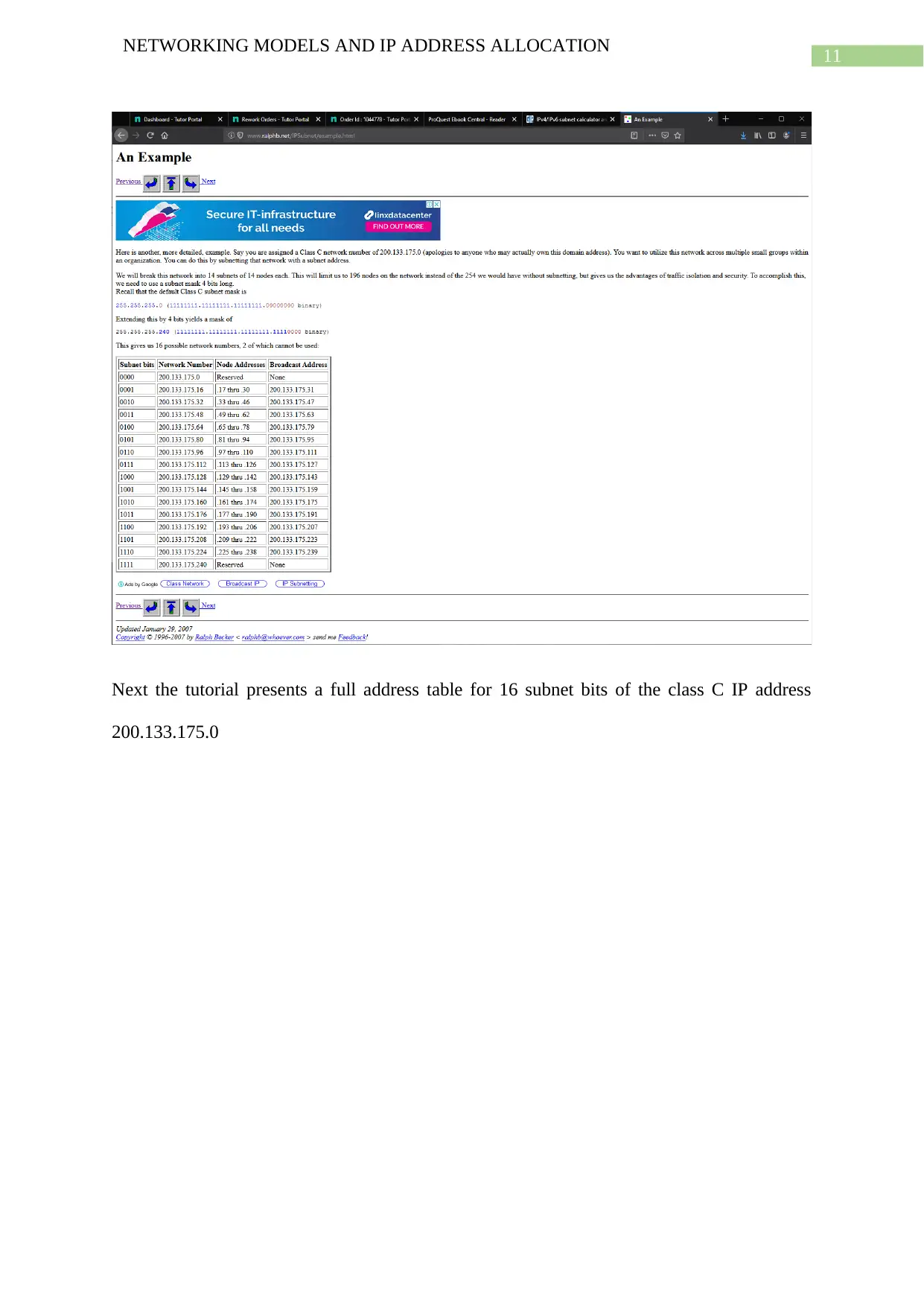
Next the tutorial presents a full address table for 16 subnet bits of the class C IP address
200.133.175.0
NETWORKING MODELS AND IP ADDRESS ALLOCATION
Next the tutorial presents a full address table for 16 subnet bits of the class C IP address
200.133.175.0
⊘ This is a preview!⊘
Do you want full access?
Subscribe today to unlock all pages.

Trusted by 1+ million students worldwide
1 out of 28
Related Documents
Your All-in-One AI-Powered Toolkit for Academic Success.
+13062052269
info@desklib.com
Available 24*7 on WhatsApp / Email
![[object Object]](/_next/static/media/star-bottom.7253800d.svg)
Unlock your academic potential
Copyright © 2020–2026 A2Z Services. All Rights Reserved. Developed and managed by ZUCOL.


