NMM3540: Development of Dimensional Measurement Metrology Case Study
VerifiedAdded on 2023/04/23
|24
|3713
|421
Case Study
AI Summary
This case study report, prepared for the NMM3540 course, presents an analysis of dimensional measurement techniques within a manufacturing context. It addresses four measurement tasks, starting with an examination of digital and manual calipers for measuring component dimensions, including data analysis on resolution, repeatability, and accuracy. Subsequent tasks involve proposing and evaluating new measurement systems for turbine bearing housings and cylindrical turbine shafts, considering factors such as tolerance ranges, production volumes, and cost-effectiveness. The report details system requirements, equipment selection, calibration procedures, maintenance plans, and Gantt charts for implementation, emphasizing quality control, traceability, and return on investment. The study explores different measurement systems, including matrix array systems and optical measurement systems, to ensure high precision and efficiency in the measurement of various components. This student assignment offers a comprehensive overview of metrology practices and their application in a precision manufacturing environment.

Measurement Case Study
Student Name:
Student number:
Date:
Student Name:
Student number:
Date:
Paraphrase This Document
Need a fresh take? Get an instant paraphrase of this document with our AI Paraphraser
2
Contents
Executive summary ......................................................................................................................... 4
Introduction ..................................................................................................................................... 4
Task 1 .............................................................................................................................................. 4
Procedure of using the instrument ............................................................................................... 4
Digital clipper .......................................................................................................................... 4
Manual clipper ......................................................................................................................... 5
Results analysis ........................................................................................................................... 6
Discussion ................................................................................................................................... 7
Task 2 .............................................................................................................................................. 8
Proposed system requirements .................................................................................................... 8
Proposed measurement system description ................................................................................. 9
reasons for the choice ................................................................................................................ 11
activity and costings and Gant chart ......................................................................................... 11
Task 3 ............................................................................................................................................ 12
Measuring requirements ............................................................................................................ 12
Proposed measurement system.................................................................................................. 13
Training and maintenances........................................................................................................ 14
Calibration ................................................................................................................................. 14
Reasons for choosing the above system .................................................................................... 14
Activity costings and Gantt chart .............................................................................................. 14
Task 4 ............................................................................................................................................ 15
Measurement equipment requirements ..................................................................................... 15
Proposed measuring system. ..................................................................................................... 15
Gantt chart and activity costings ............................................................................................... 19
Conclusion .................................................................................................................................... 21
References ................................................................................................................................ 23
Figure 1 digital clipper used in measuring the part surface. ........................................................... 4
Figure 2 showing a sample of holes to be measured image from (contributors, 2019) .................. 8

3
Figure 3 digital Vernier caliper with range of 0mm to 150mm, no zero error and with inner
diameter claw, image credit (caliper ,2019) .................................................................................. 10
Figure 4 on/off for digital caliper image from Wonkeedonkeetools.co.uk. (2019). ..................... 11
Figure 5 caliper storing box, image from Wonkeedonkeetools.co.uk. (2019). ............................ 11
Figure 6 full pack digital caliper costs 23.99 us dollars, image from Amazon website, 2019 ..... 12
Figure 7 table showing activities and their costings, with Gantt chart timeline for activities ...... 12
Figure 8 matrix array measuring system Qualitymag.com. (2019). ............................................. 13
Figure 9 showing matrix array scan for the system, image from Qualitymag.com. (2019). ........ 14
Figure 10 activity costing and Gant chart ..................................................................................... 15
Figure 11 optical measuring system ............................................................................................. 16
Figure 12 Figure 3 larger system will be adopted to allow measurement of variety of components
(Nugent, 2019) .............................................................................................................................. 17
Figure 13 Gantt chart showing proposed timeline for activities ................................................... 21
Table 1 showing activity costing and the Gantt chart activities ................................................... 19
⊘ This is a preview!⊘
Do you want full access?
Subscribe today to unlock all pages.
Trusted by 1+ million students worldwide
4
Executive summary
This report presents series of data analysis of an experiment done in the laboratory. The
assignment involves four measuring tasks. The first task will involve analysing the measured
data in consideration with resolution and repeatability. This will lead to high accuracy in
measurements. The measurement task two, three and four involves introducing new
measurement system. The role of the task will involve analysing the probable equipment needed
for high precision measurement.
Introduction
Dimensional measurement refers to a field of science that specializes in metrology
(Muelaner, 2019). It gives understanding of units across continents, which is crucial for linking
human activities (Finkelstein, 2009). Modern dimensioning has its origins in in the political
motivation of the French Revolution to standardize units in France when a long standard was
suggested from a natural source (paktar, 2009). This led to the establishment in 1795 of the
decimal-based metric systems, which established a set of standards for other calibration types.
Between 1867 and 1976, several other nations adopted the imperial system; the Meter
Convention established the Bureau International les Poids et Measures to ensure uniformity
between the countries (Nugent, 2019).
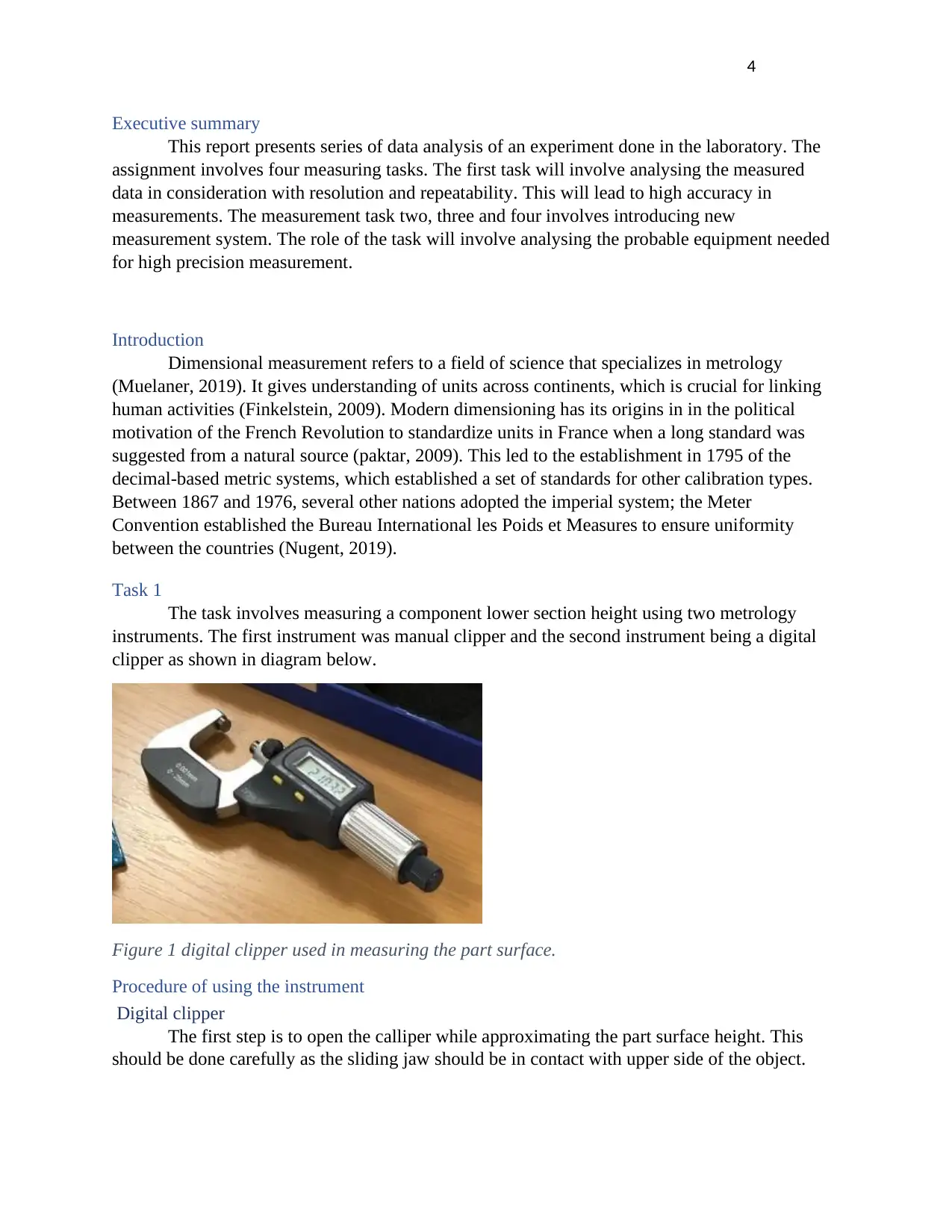
Task 1
The task involves measuring a component lower section height using two metrology
instruments. The first instrument was manual clipper and the second instrument being a digital
clipper as shown in diagram below.
Figure 1 digital clipper used in measuring the part surface.
Procedure of using the instrument
Digital clipper
The first step is to open the calliper while approximating the part surface height. This
should be done carefully as the sliding jaw should be in contact with upper side of the object.
Executive summary
This report presents series of data analysis of an experiment done in the laboratory. The
assignment involves four measuring tasks. The first task will involve analysing the measured
data in consideration with resolution and repeatability. This will lead to high accuracy in
measurements. The measurement task two, three and four involves introducing new
measurement system. The role of the task will involve analysing the probable equipment needed
for high precision measurement.
Introduction
Dimensional measurement refers to a field of science that specializes in metrology
(Muelaner, 2019). It gives understanding of units across continents, which is crucial for linking
human activities (Finkelstein, 2009). Modern dimensioning has its origins in in the political
motivation of the French Revolution to standardize units in France when a long standard was
suggested from a natural source (paktar, 2009). This led to the establishment in 1795 of the
decimal-based metric systems, which established a set of standards for other calibration types.
Between 1867 and 1976, several other nations adopted the imperial system; the Meter
Convention established the Bureau International les Poids et Measures to ensure uniformity
between the countries (Nugent, 2019).
Task 1
The task involves measuring a component lower section height using two metrology
instruments. The first instrument was manual clipper and the second instrument being a digital
clipper as shown in diagram below.
Figure 1 digital clipper used in measuring the part surface.
Procedure of using the instrument
Digital clipper
The first step is to open the calliper while approximating the part surface height. This
should be done carefully as the sliding jaw should be in contact with upper side of the object.
Paraphrase This Document
Need a fresh take? Get an instant paraphrase of this document with our AI Paraphraser
5
In the second step, the jaws of lower calliper are extended until the jaws meet the lower side of
the part surface. To extend the jaws, a thumb screw is used.
The third step is to lock the jaws, in between is the part surface to be measured. Tighten
the jaws and remove the part surface if need be.
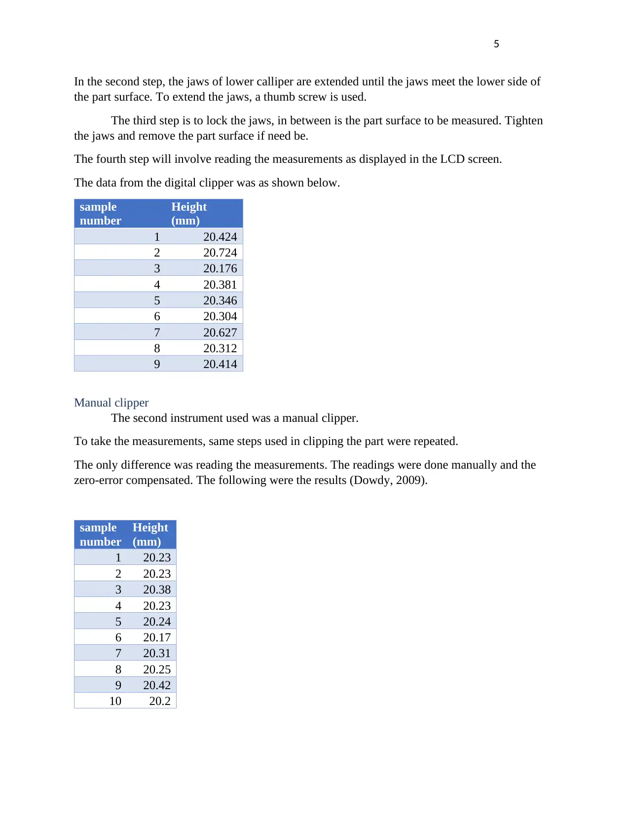
The fourth step will involve reading the measurements as displayed in the LCD screen.
The data from the digital clipper was as shown below.
sample
number
Height
(mm)
1 20.424
2 20.724
3 20.176
4 20.381
5 20.346
6 20.304
7 20.627
8 20.312
9 20.414
Manual clipper
The second instrument used was a manual clipper.
To take the measurements, same steps used in clipping the part were repeated.
The only difference was reading the measurements. The readings were done manually and the
zero-error compensated. The following were the results (Dowdy, 2009).
sample
number
Height
(mm)
1 20.23
2 20.23
3 20.38
4 20.23
5 20.24
6 20.17
7 20.31
8 20.25
9 20.42
10 20.2
In the second step, the jaws of lower calliper are extended until the jaws meet the lower side of
the part surface. To extend the jaws, a thumb screw is used.
The third step is to lock the jaws, in between is the part surface to be measured. Tighten
the jaws and remove the part surface if need be.
The fourth step will involve reading the measurements as displayed in the LCD screen.
The data from the digital clipper was as shown below.
sample
number
Height
(mm)
1 20.424
2 20.724
3 20.176
4 20.381
5 20.346
6 20.304
7 20.627
8 20.312
9 20.414
Manual clipper
The second instrument used was a manual clipper.
To take the measurements, same steps used in clipping the part were repeated.
The only difference was reading the measurements. The readings were done manually and the
zero-error compensated. The following were the results (Dowdy, 2009).
sample
number
Height
(mm)
1 20.23
2 20.23
3 20.38
4 20.23
5 20.24
6 20.17
7 20.31
8 20.25
9 20.42
10 20.2
6
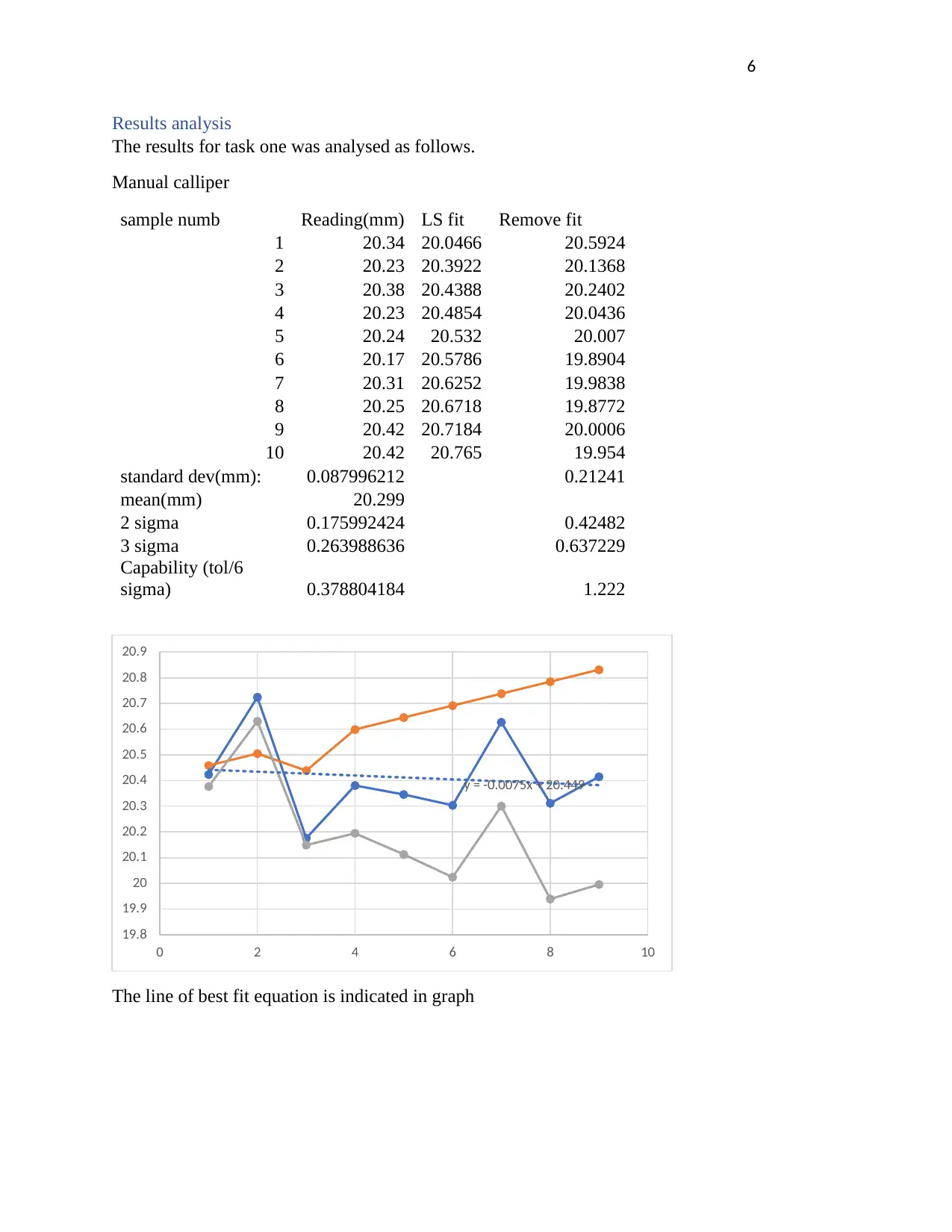
Results analysis
The results for task one was analysed as follows.
Manual calliper
sample numb Reading(mm) LS fit Remove fit
1 20.34 20.0466 20.5924
2 20.23 20.3922 20.1368
3 20.38 20.4388 20.2402
4 20.23 20.4854 20.0436
5 20.24 20.532 20.007
6 20.17 20.5786 19.8904
7 20.31 20.6252 19.9838
8 20.25 20.6718 19.8772
9 20.42 20.7184 20.0006
10 20.42 20.765 19.954
standard dev(mm): 0.087996212 0.21241
mean(mm) 20.299
2 sigma 0.175992424 0.42482
3 sigma 0.263988636 0.637229
Capability (tol/6
sigma) 0.378804184 1.222
The line of best fit equation is indicated in graph
y = -0.0075x + 20.449
19.8
19.9
20
20.1
20.2
20.3
20.4
20.5
20.6
20.7
20.8
20.9
0 2 4 6 8 10
⊘ This is a preview!⊘
Do you want full access?
Subscribe today to unlock all pages.
Trusted by 1+ million students worldwide
7
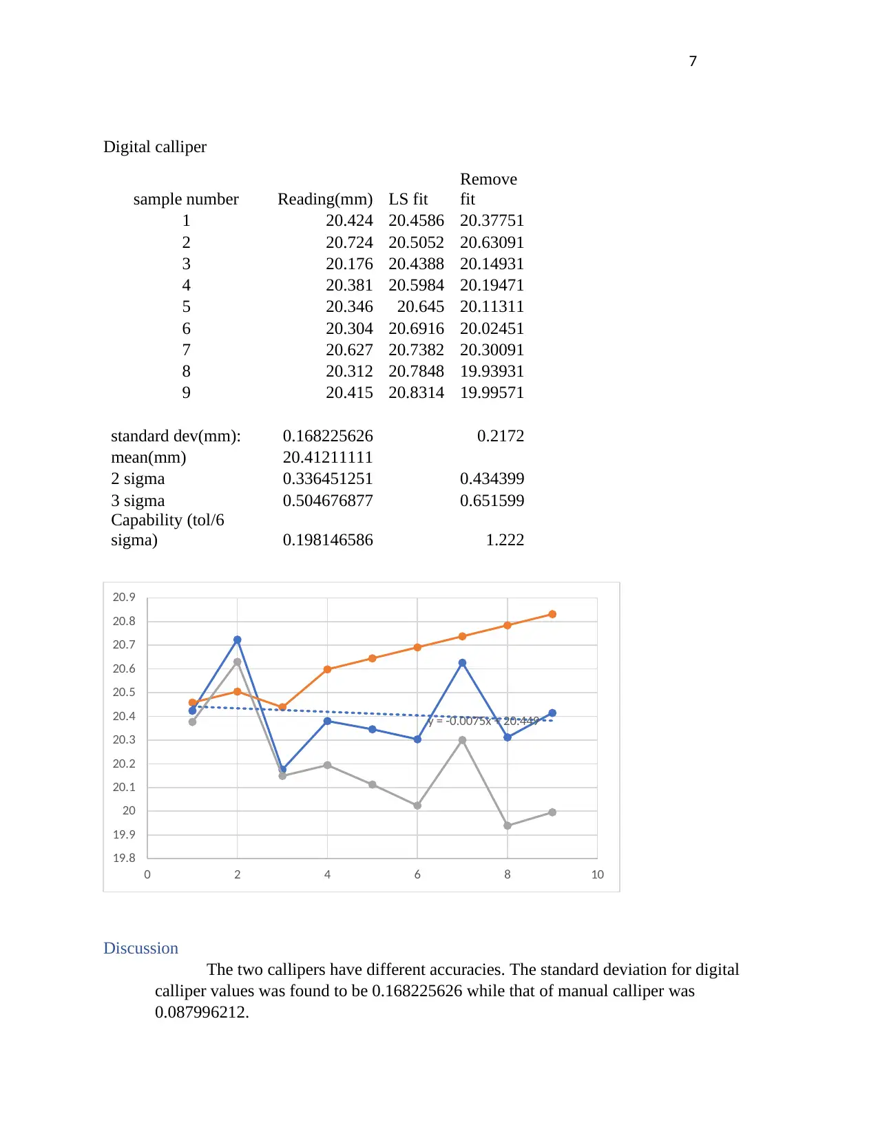
Digital calliper
sample number Reading(mm) LS fit
Remove
fit
1 20.424 20.4586 20.37751
2 20.724 20.5052 20.63091
3 20.176 20.4388 20.14931
4 20.381 20.5984 20.19471
5 20.346 20.645 20.11311
6 20.304 20.6916 20.02451
7 20.627 20.7382 20.30091
8 20.312 20.7848 19.93931
9 20.415 20.8314 19.99571
standard dev(mm): 0.168225626 0.2172
mean(mm) 20.41211111
2 sigma 0.336451251 0.434399
3 sigma 0.504676877 0.651599
Capability (tol/6
sigma) 0.198146586 1.222
Discussion
The two callipers have different accuracies. The standard deviation for digital
calliper values was found to be 0.168225626 while that of manual calliper was
0.087996212.
y = -0.0075x + 20.449
19.8
19.9
20
20.1
20.2
20.3
20.4
20.5
20.6
20.7
20.8
20.9
0 2 4 6 8 10
Paraphrase This Document
Need a fresh take? Get an instant paraphrase of this document with our AI Paraphraser
8
The two instruments have uncertainties in their measurements. The readings in digital calliper
cannot be predicted since they keep changing. The manual calliper has high repeatability than the
digital calliper. Digital calliper is suitable for large scale measurements since its fast as compared
to manual calliper. Compared to Vernier callipers, the digital calliper is more reliable for batch
measurements, but with high tolerances. The manual calliper is accurate, but is subject to human
error, using it for measuring small batch components could be tiresome. Human errors would
inconvenience the final results.
Reasons for uncertainties and how to reduce them
Good measurements should be made without the influence of ambient factors. The
following are the main reasons why the instruments does not give consistent readings.
• Room temperature changes
• Parallax
• Humidity
• Instrument errors
Possible solutions to the above problems
• Perform the measurements in well controlled zone
• Avoid human errors, such as parallax
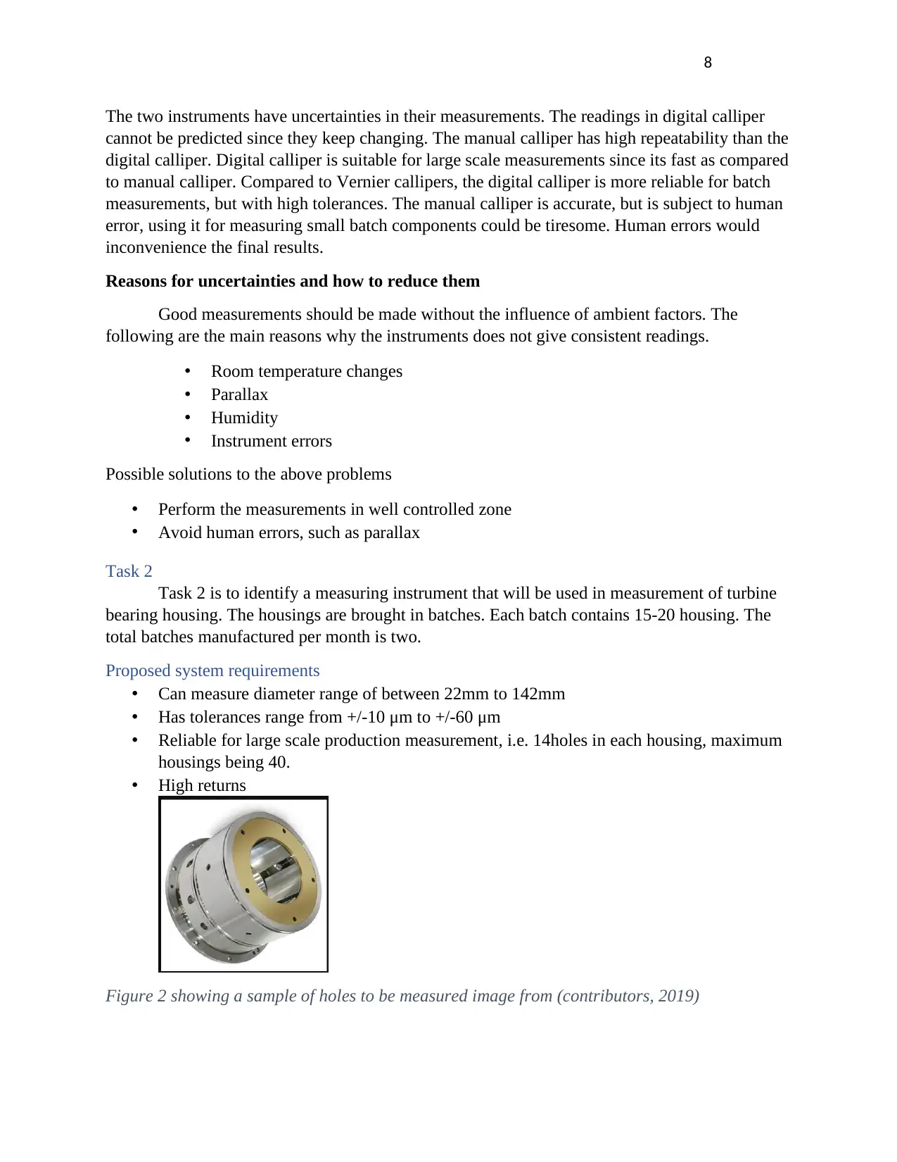
Task 2
Task 2 is to identify a measuring instrument that will be used in measurement of turbine
bearing housing. The housings are brought in batches. Each batch contains 15-20 housing. The
total batches manufactured per month is two.
Proposed system requirements
• Can measure diameter range of between 22mm to 142mm
• Has tolerances range from +/-10 μm to +/-60 μm
• Reliable for large scale production measurement, i.e. 14holes in each housing, maximum
housings being 40.
• High returns
Figure 2 showing a sample of holes to be measured image from (contributors, 2019)
The two instruments have uncertainties in their measurements. The readings in digital calliper
cannot be predicted since they keep changing. The manual calliper has high repeatability than the
digital calliper. Digital calliper is suitable for large scale measurements since its fast as compared
to manual calliper. Compared to Vernier callipers, the digital calliper is more reliable for batch
measurements, but with high tolerances. The manual calliper is accurate, but is subject to human
error, using it for measuring small batch components could be tiresome. Human errors would
inconvenience the final results.
Reasons for uncertainties and how to reduce them
Good measurements should be made without the influence of ambient factors. The
following are the main reasons why the instruments does not give consistent readings.
• Room temperature changes
• Parallax
• Humidity
• Instrument errors
Possible solutions to the above problems
• Perform the measurements in well controlled zone
• Avoid human errors, such as parallax
Task 2
Task 2 is to identify a measuring instrument that will be used in measurement of turbine
bearing housing. The housings are brought in batches. Each batch contains 15-20 housing. The
total batches manufactured per month is two.
Proposed system requirements
• Can measure diameter range of between 22mm to 142mm
• Has tolerances range from +/-10 μm to +/-60 μm
• Reliable for large scale production measurement, i.e. 14holes in each housing, maximum
housings being 40.
• High returns
Figure 2 showing a sample of holes to be measured image from (contributors, 2019)

9
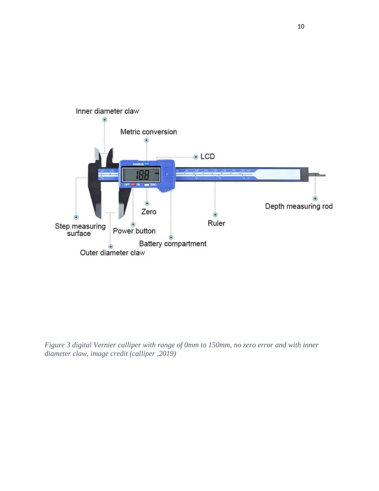
Proposed measurement system description
The proposed system must meet the required description above. In measuring the bearing holes,
a precise measurement tool is needed, for our case, a digital Vernier calliper will be used.
The calliper can measure in range of 1mm to 150mm as shown below.
The inner diameter claw will be used to measure the hole bearings.
Measuring method training
As discussed before, using digital calliper is much easier. The first step is to open the calliper
while approximating the part diameter to be measured. This should be done carefully as the
sliding jaw should be in contact with the hole part, the difference between task 1 calliper and this
case is the diameter type. The main goal is to achieve inner diameter of the hole.
In the second step, the jaws of lower calliper are extended until the jaws meets the opposite inner
side of the part diameter. To extend the jaws, a thumb screw is used.
The third step is to lock the jaws, in between is the part surface to be measured. Tighten the jaws
and remove the housing if need be. The fourth step will involve reading the measurements as
displayed in the LCD screen.
Calibration
Since production is done in batches, it is expected that bearing housing of same batch same
tolerances. Calibration will be done twice in a moth, for batch 1 and batch two. This will allow
the company technicians to use sampling techniques for measurements. All bearings could also
be tested since there are only 40 bearings in total span of one month.
⊘ This is a preview!⊘
Do you want full access?
Subscribe today to unlock all pages.
Trusted by 1+ million students worldwide
10
Figure 3 digital Vernier calliper with range of 0mm to 150mm, no zero error and with inner
diameter claw, image credit (calliper ,2019)
Figure 3 digital Vernier calliper with range of 0mm to 150mm, no zero error and with inner
diameter claw, image credit (calliper ,2019)
Paraphrase This Document
Need a fresh take? Get an instant paraphrase of this document with our AI Paraphraser
11
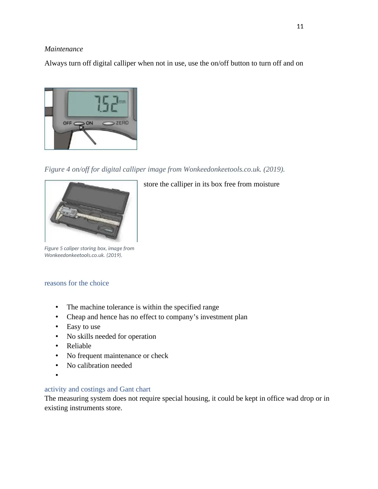
Maintenance
Always turn off digital calliper when not in use, use the on/off button to turn off and on
Figure 4 on/off for digital calliper image from Wonkeedonkeetools.co.uk. (2019).
store the calliper in its box free from moisture
reasons for the choice
• The machine tolerance is within the specified range
• Cheap and hence has no effect to company’s investment plan
• Easy to use
• No skills needed for operation
• Reliable
• No frequent maintenance or check
• No calibration needed
•
activity and costings and Gant chart
The measuring system does not require special housing, it could be kept in office wad drop or in
existing instruments store.
Figure 5 caliper storing box, image from
Wonkeedonkeetools.co.uk. (2019).
12
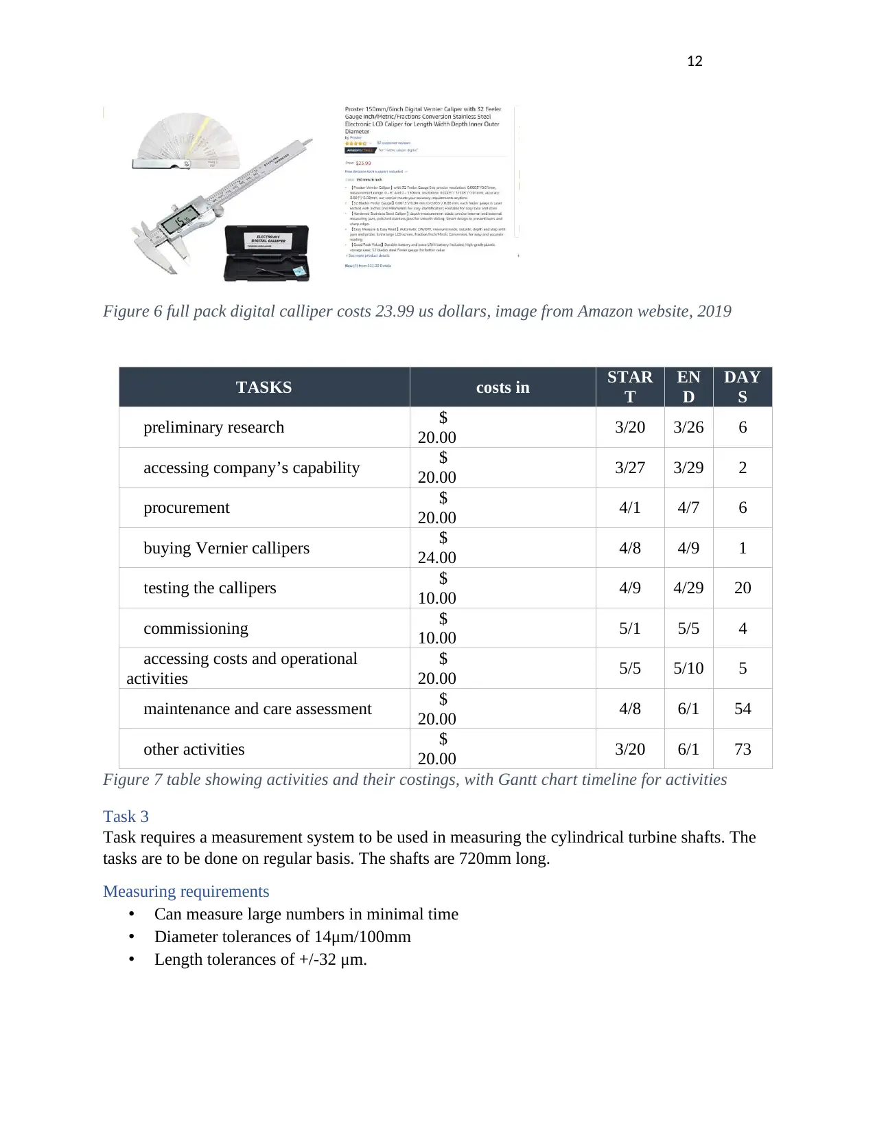
Figure 6 full pack digital calliper costs 23.99 us dollars, image from Amazon website, 2019
TASKS costs in STAR
T
EN
D
DAY
S
preliminary research $
20.00 3/20 3/26 6
accessing company’s capability $
20.00 3/27 3/29 2
procurement $
20.00 4/1 4/7 6
buying Vernier callipers $
24.00 4/8 4/9 1
testing the callipers $
10.00 4/9 4/29 20
commissioning $
10.00 5/1 5/5 4
accessing costs and operational
activities
$
20.00 5/5 5/10 5
maintenance and care assessment $
20.00 4/8 6/1 54
other activities $
20.00 3/20 6/1 73
Figure 7 table showing activities and their costings, with Gantt chart timeline for activities
Task 3
Task requires a measurement system to be used in measuring the cylindrical turbine shafts. The
tasks are to be done on regular basis. The shafts are 720mm long.
Measuring requirements
• Can measure large numbers in minimal time
• Diameter tolerances of 14μm/100mm
• Length tolerances of +/-32 μm.
⊘ This is a preview!⊘
Do you want full access?
Subscribe today to unlock all pages.
Trusted by 1+ million students worldwide
1 out of 24
Related Documents


Your All-in-One AI-Powered Toolkit for Academic Success.
+13062052269
info@desklib.com
Available 24*7 on WhatsApp / Email
![[object Object]](/_next/static/media/star-bottom.7253800d.svg)
Unlock your academic potential
Copyright © 2020–2025 A2Z Services. All Rights Reserved. Developed and managed by ZUCOL.