Optimization of Shell and Tube Heat Exchanger Research Project Thesis
VerifiedAdded on 2022/11/11
|45
|9969
|2
Project
AI Summary
This Master of Engineering Technology research project focuses on the optimization of shell and tube heat exchangers (STHEs). The study begins with an overview of heat exchangers, including their applications and importance in various industries such as chemical plants and power production. The project aims to analyze and improve the performance efficiency of STHEs through experimentation and software analysis, specifically using Particle Swarm Optimization (PSO) to address design parameters like baffle spacing and tube dimensions. The research covers design considerations, thermal design calculations, and the creation of a 3D model using Autodesk Inventor. The report includes details on the research methodology, design process, experimental calculations, and CFD analysis to validate the design calculations. The project also addresses the efficiency and effectiveness of STHEs, providing a comprehensive understanding of the design and optimization process for these critical industrial components. The project also includes MATLAB simulations and design diagrams.
OPTIMISATION OF SHELL AND TUBE HEAT EXCHANGER i
M o u n t H e l e n C a m p u s
S c h o o l o f S c i e n c e , E n g i n e e r i n g a n d
I n f o r m a t i o n T e c h n o l o g y
Master of Engineering
Technology Degree
Research Project Thesis
2019
Optimization of Shell and
Tube Heat Exchanger
S u b m i t t e d b y :
S t u d e n t I D :
S t r e a m :
S u p e r v i s o r :
D a t e :
Paraphrase This Document
Need a fresh take? Get an instant paraphrase of this document with our AI Paraphraser

OPTIMISATION OF SHELL AND TUBE HEAT EXCHANGER ii
Acknowledgement:
Before starting with the research proposal, it’s with great pleasure to thank Dr.Ibrahim Sultan my
supervisor and advisor for his overwhelmingly help in the selection of topic and the fruitful
discussion which we had on the topic “Optimization of shell and tube heat exchanger”. Secondly I
share my gratitude to all friends who had all been part and parcel in helping me out in the successful
completion of my project proposal. It takes my immense privilege in proclaiming that without all
these people my project which includes the analysis of working of the Heat exchanger would all
have been in vain.
OPTIMISATION OF SHELL AND TUBE HEAT EXCHANGER iii
ABSTRACT.
Most if not all industrial processes in one way or another are associated with heat transfer in the
form of thermal energy differences in working fluids having thermal disparity. The device that
facilitates this thermal energy transfer is referred as heat exchanger. Heat exchangers are essential
in many industrial processes. Thus the productivity of any process is affected by the working
condition, status and overall efficiency of this device. Because of their importance, they widely
applied in chemical plants, mechanical manufacturing, air conditioning, and even refrigeration.
Shell and tube heat exchangers STHEs are most efficient exchanger of all types of heat exchangers,
and this has seen its application widen in different industrial applications such as chemical process,
power production industries, and refining plants. Most general solicitation of thermal transfer is in
designing of heat transfer apparatus for thermal exchange from fluid to another. Heat exchangers
are normally categorized concerning transfer process taking place in them
The objective of this project is to analyze performance efficiency of optimum shell and tube heat
exchangers through experimentation and software analysis (Naphon, 207). Design parameters are
formulated and computed in the form of optimization problems which are solved through Particle
Swarm Optimization (PSO). This optimization intends to reduce cost and expenses such as pumping
and area cost of these devices. All calculations and specification of the design parameters in this
paper are arrived at in consideration to Tubular Exchanger Manufacturers Association with pressure
drops and fouling limits. Values obtained in chapter four of this paper are considered most
appropriate in designing an optimized shell and tube heat exchanger. Verification results are also
listed providing proof of validation on the design calculations.
This report begins with bits of theory, providing general knowledge on heat exchanger with a
summarised introduction to heat exchangers. Overview of literature together with some recent
developments achieved towards optimization of heat exchangers. Matlab simulations and design
diagrams are also featured.
⊘ This is a preview!⊘
Do you want full access?
Subscribe today to unlock all pages.
Trusted by 1+ million students worldwide
OPTIMISATION OF SHELL AND TUBE HEAT EXCHANGER iv
Table of Content
DECLARATION..................................................................................................................................i
ACKNOWLEDGEMENT:..................................................................................................................II
ABSTRACT........................................................................................................................................iii
List of figures………………………………………………………………………………………..
List of tables………………………………………………………………………………………….
Nomenclature……………………………………………………………………………………….
CHAPTER 1.........................................................................................................................................6
INTRODUCTION................................................................................................................................6
1.1 Background information.............................................................................................................6
1.2 Problem Statement.....................................................................................................................7
1.2.1 Selection of shell and tube heat exchanger:........................................................................8
1.2.2 Fixed tube heat exchanger.............................................................................................9
1.2.3 Removable type heat exchanger:.........................................................................................9
1.3 Classification of Heat Exchangers:....................................................................................10
1.3.1 Heat Exchanger Nomenclature:.........................................................................................11
1.3.2 Part names.........................................................................................................................11
CHAPTER TWO................................................................................................................................14
OVERVIEW OF OPTIMIZING SHELL AND TUBE HEAT EXCHANGER................................14
2.1 Overview of Heat Exchangers..................................................................................................14
2.1.1 The gravity film heat exchanger........................................................................................15
2.1.2 Plate Heat Exchangers.......................................................................................................15
2.1.3 Tube and Coil Drain Heat Recovery.................................................................................16
2.3 Existing heat exchangers..........................................................................................................16
2.3.1 Fixed tube sheet.................................................................................................................16
2.3.2 U-Tube...............................................................................................................................17
2.3.3Floating tubesheet...............................................................................................................17
2.4 Thermal Design Consideration:................................................................................................17
2.4.1 Shell design consideration:................................................................................................17
2.4.2 Tube design consideration:................................................................................................18
2.4.3 Tube pitch and tube layout:...............................................................................................18
2.4.4 Tube sheet design:.............................................................................................................18
2.4.5 Baffle Design:....................................................................................................................18
2.4.6 Valves………………………………………………………………………………………..
2.5 Two types of passes..................................................................................................................20
Paraphrase This Document
Need a fresh take? Get an instant paraphrase of this document with our AI Paraphraser
OPTIMISATION OF SHELL AND TUBE HEAT EXCHANGER v
2.5.1 Single pass unit..................................................................................................................20
2.5.2 Multipass unit....................................................................................................................20
CHAPTER THREE............................................................................................................................21
RESEARCH METHODOLOGY AND DESIGN PROCESS...........................................................21
3.1 Design process..........................................................................................................................21
3.2 Maintenance.............................................................................................................................21
3.3 Cost...........................................................................................................................................21
3.4 Safety........................................................................................................................................21
3.5 Design procedure......................................................................................................................22
3.5.2 Convective heat transfer coefficient (h)............................................................................23
3.5.3 Baffle cut and spacing.......................................................................................................24
3.6 Correction factor.......................................................................................................................25
3.7 Experimental calculation:.........................................................................................................28
Chapter 4............................................................................................................................................29
Optimization of the design process....................................................................................................29
4.1 Tube design calculations..........................................................................................................29
Chapter 5...........................................................................................................................................32
Design of shell and tube heat exchanger:-..........................................................................................32
5.1 Design of 3DModel of shell and tube heat exchanger by using Autodesk Inventor................33
5.2 Efficiency:................................................................................................................................33
5.3 Effectiveness:........................................................................................................................33
5.3.1 Tube pass...........................................................................................................................34
5.3.2 Tube pitch..........................................................................................................................34
Chapter - 6..........................................................................................................................................35
Results for CFD analysis: -................................................................................................................35
Chapter - 7..........................................................................................................................................38
Conclusion: -......................................................................................................................................38
Chapter - 8..........................................................................................................................................39
Recommendations of future work: -...................................................................................................39
Chapter - 9..........................................................................................................................................40
Reference:...........................................................................................................................................40
OPTIMISATION OF SHELL AND TUBE HEAT EXCHANGER vi
List of Figures
Figure 1.1 simple shell and tube heat exchanger
Figure 1.2 components of shell and tube heat exchanger (Wilfried & Deiying, 2007)
Figure 1.3 Heat exchangers based on application
Figure 1.4 shell and tube heat exchanger
Figure 1.5 parts shell and tube heat exchanger
Figure 1.6 TEMA standards configuration of STHE (Wen et al., 2016)
Figure 2.1 Tube Layout types (Wen et al., 2016)
Figure 3.1 Triangular Pitch and Clearance
5.1 Design of 3DModel of shell and tube heat exchanger by using Autodesk Inventor
5.2 Design of 3DModel of shell and tube heat exchanger by using Autodesk Inventor
Figure 6.1 Velocity Profile
Figure 6.2 Velocity Vector
List of Tables
Table 4.1 shows the design dimensions
Table 6.1 Velocity Magnitude
Table 6.2 Temperature Magnitude
Table 6.3 Pressure Magnitude
Nomenclature
⊘ This is a preview!⊘
Do you want full access?
Subscribe today to unlock all pages.
Trusted by 1+ million students worldwide
OPTIMISATION OF SHELL AND TUBE HEAT EXCHANGER vii
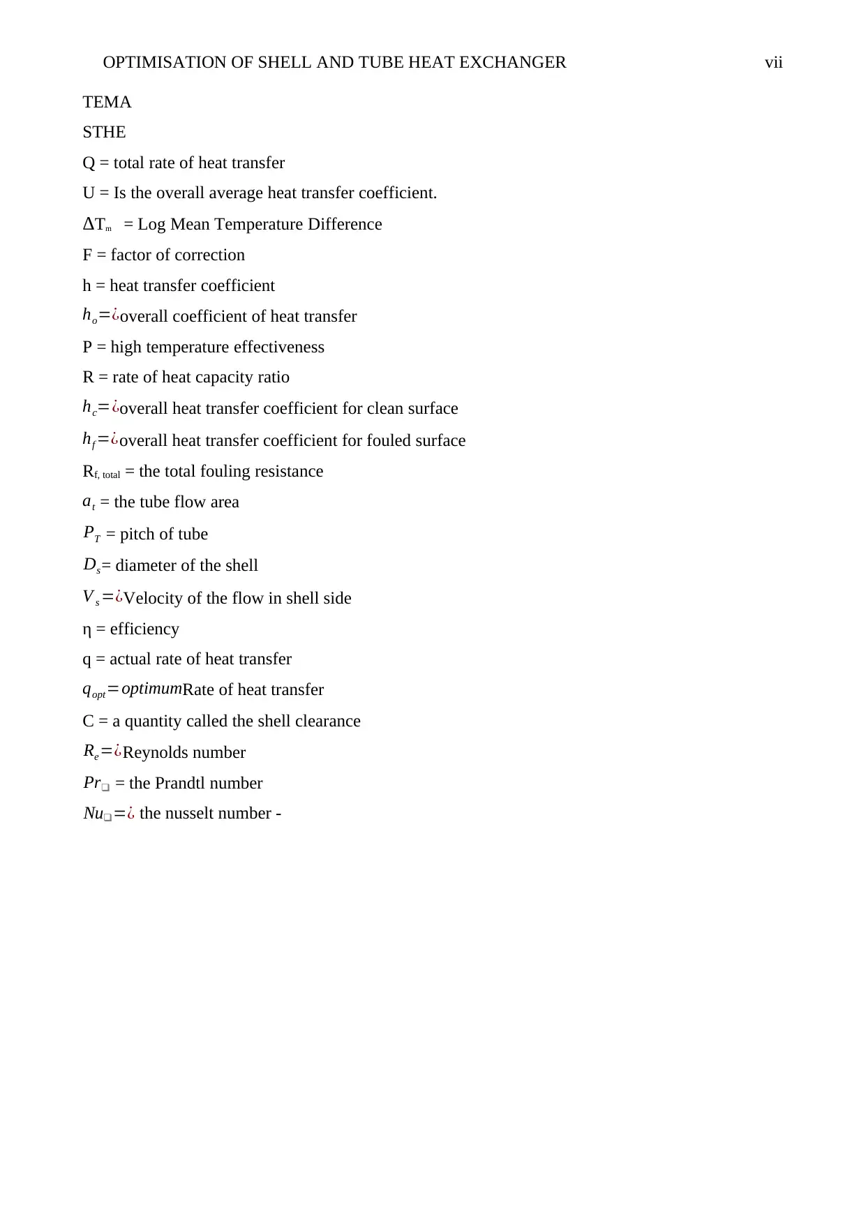
TEMA
STHE
Q = total rate of heat transfer
U = Is the overall average heat transfer coefficient.
ΔTm = Log Mean Temperature Difference
F = factor of correction
h = heat transfer coefficient
ho=¿overall coefficient of heat transfer
P = high temperature effectiveness
R = rate of heat capacity ratio
hc=¿overall heat transfer coefficient for clean surface
hf =¿overall heat transfer coefficient for fouled surface
Rf, total = the total fouling resistance
at = the tube flow area
PT = pitch of tube
Ds= diameter of the shell
V s =¿Velocity of the flow in shell side
η = efficiency
q = actual rate of heat transfer
qopt=optimumRate of heat transfer
C = a quantity called the shell clearance
Re=¿Reynolds number
Pr❑ = the Prandtl number
Nu❑=¿ the nusselt number -
Paraphrase This Document
Need a fresh take? Get an instant paraphrase of this document with our AI Paraphraser
OPTIMISATION OF SHELL AND TUBE HEAT EXCHANGER viii
CHAPTER 1
INTRODUCTION
1.1 Background information
Objective: -
Best design and material selection should be considered to achieve the best efficiency of a heat
exchanger. The design parameters have to look at different conditions of exchanger use and feel
their needs. The best design can be achieved for heat exchanger (Mirzaei el al., 2017) influence the
efficiency of the diameter of the pipelines. It seeks shell and tube heat exchanger is the best among
several types and has high in demand (Gay et al., 2012) A shell and tube heat exchanger is a class of
heat exchanger designs. It is the most common type of heat exchanger in oil refineries and other
extensive chemical processes and is suited for higher -pressure applications (Coulson &
Richardson, 2005).
This type of heat exchanger consists of a shell which is a high-pressure vessel with a bundle of
tubes inside it. One fluid runs through the tubes, and another fluid flows over the tubes, which
means through the shell to transfer heat between the two fluids (Martinez el al., 2018). The set of
tubes is called a tube bundle and may be composed of several types of tubes such as dull,
longitudinally finned. In most industrial applications of nowadays involve application of heat
exchangers. Their popularity is widely contributed by cost minimisation thus making their use more
economical both for the designers and industrial users (Rao et al., 2017). Designers have been
working all time around the clock to improve in the working efficiency by incorporating more
complex processes that into details include selection operating parameters together with geometric
parameters. Latest models of these shell and tube heat exchangers have more advantages over the
conventional ones since they assure optimal solutions and takes less time thus doesn’t waste time as
compared to the traditional design approach.
On this account the study tends to explore and expound on the use of modern optimisation
techniques such as particle swarm optimisation (PSO) in shell and tube heat exchangers
optimisation design (Mohanty, 2016). Through this economic efficiency of the design is achieved.
One of the objectives in the design of these shell and tube heat exchangers is minimising the yearly
operation cost. This can only be achieved by considering three different design variables such as
baffle spacing for optimization, internal shell diameter and tube outer diameter in both two layouts,
that is square and triangle layouts.( Bevevino et al., 2014)
OPTIMISATION OF SHELL AND TUBE HEAT EXCHANGER ix
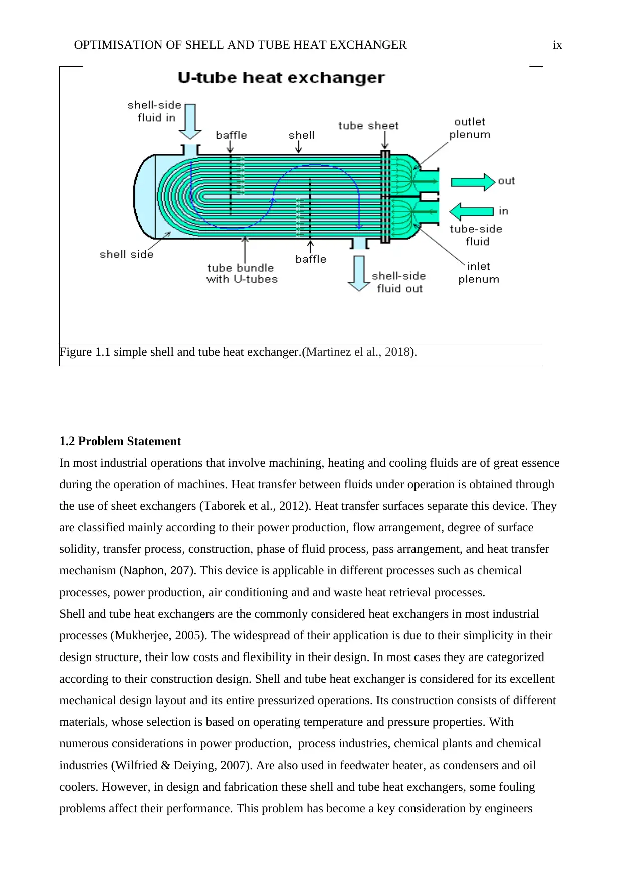
Figure 1.1 simple shell and tube heat exchanger.(Martinez el al., 2018).
1.2 Problem Statement
In most industrial operations that involve machining, heating and cooling fluids are of great essence
during the operation of machines. Heat transfer between fluids under operation is obtained through
the use of sheet exchangers (Taborek et al., 2012). Heat transfer surfaces separate this device. They
are classified mainly according to their power production, flow arrangement, degree of surface
solidity, transfer process, construction, phase of fluid process, pass arrangement, and heat transfer
mechanism (Naphon, 207). This device is applicable in different processes such as chemical
processes, power production, air conditioning and and waste heat retrieval processes.
Shell and tube heat exchangers are the commonly considered heat exchangers in most industrial
processes (Mukherjee, 2005). The widespread of their application is due to their simplicity in their
design structure, their low costs and flexibility in their design. In most cases they are categorized
according to their construction design. Shell and tube heat exchanger is considered for its excellent
mechanical design layout and its entire pressurized operations. Its construction consists of different
materials, whose selection is based on operating temperature and pressure properties. With
numerous considerations in power production, process industries, chemical plants and chemical
industries (Wilfried & Deiying, 2007). Are also used in feedwater heater, as condensers and oil
coolers. However, in design and fabrication these shell and tube heat exchangers, some fouling
problems affect their performance. This problem has become a key consideration by engineers
⊘ This is a preview!⊘
Do you want full access?
Subscribe today to unlock all pages.
Trusted by 1+ million students worldwide
OPTIMISATION OF SHELL AND TUBE HEAT EXCHANGER x
trying to find the most suitable solution to this problem. Fouling refers to aggregation of
undesirable material deposition on surface of heat exchanger which decreases the rate of heat
transfer and increases the resistance to fluid flow, thus resulting unnecessary high-pressure drop
(Patel et al., 2012).
So, the transfer of heat from fluid to another is an critical process in chemical industries and
refrigeration industries. Shell and tube heat exchanger is one of the most efficient types of
equipment for this application. For chemical industries, chemical and water are two fluids whereas,
for refrigeration industries, refrigerant and water can be both fluids.
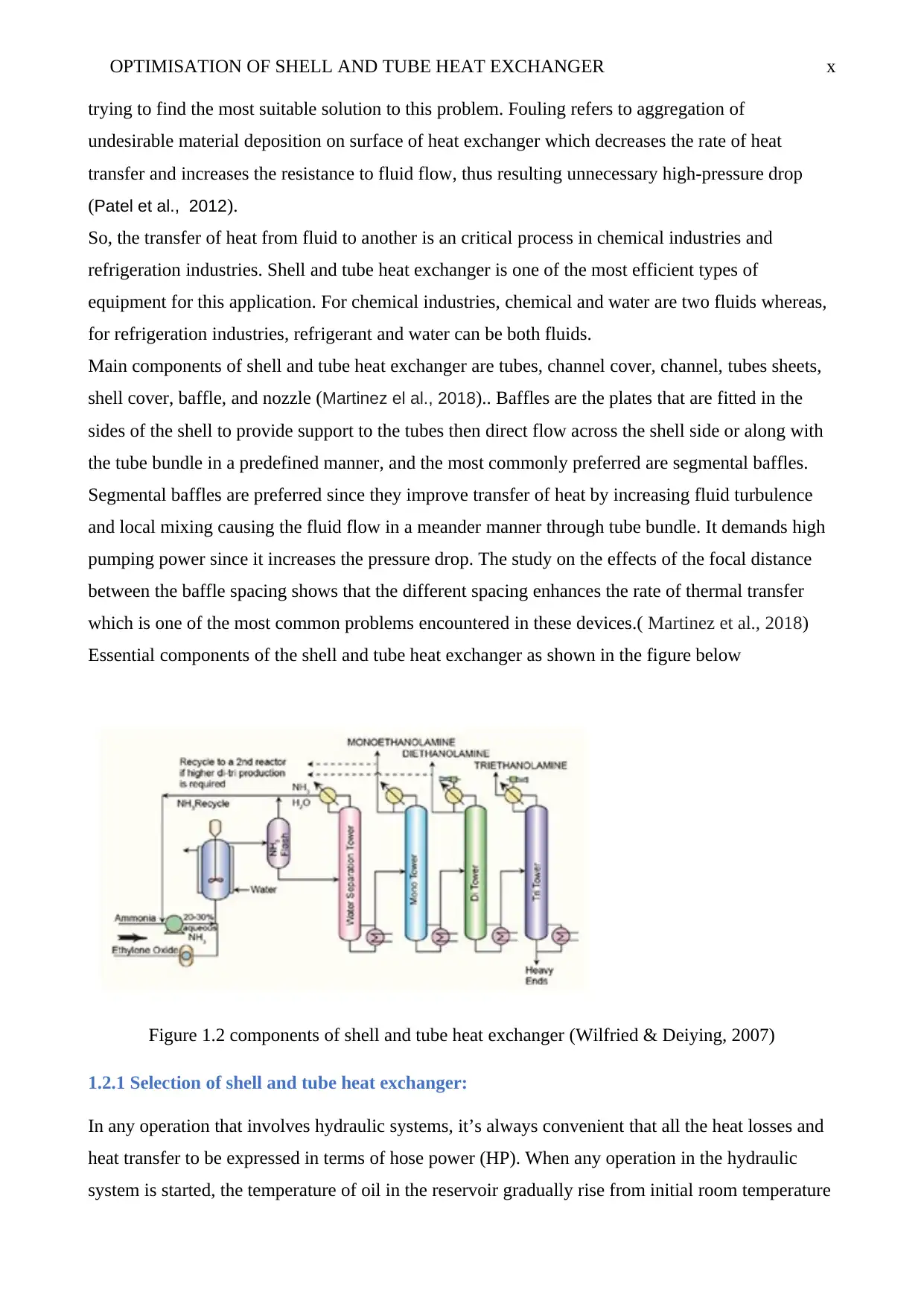
Main components of shell and tube heat exchanger are tubes, channel cover, channel, tubes sheets,
shell cover, baffle, and nozzle (Martinez el al., 2018).. Baffles are the plates that are fitted in the
sides of the shell to provide support to the tubes then direct flow across the shell side or along with
the tube bundle in a predefined manner, and the most commonly preferred are segmental baffles.
Segmental baffles are preferred since they improve transfer of heat by increasing fluid turbulence
and local mixing causing the fluid flow in a meander manner through tube bundle. It demands high
pumping power since it increases the pressure drop. The study on the effects of the focal distance
between the baffle spacing shows that the different spacing enhances the rate of thermal transfer
which is one of the most common problems encountered in these devices.( Martinez et al., 2018)
Essential components of the shell and tube heat exchanger as shown in the figure below
Figure 1.2 components of shell and tube heat exchanger (Wilfried & Deiying, 2007)
1.2.1 Selection of shell and tube heat exchanger:
In any operation that involves hydraulic systems, it’s always convenient that all the heat losses and
heat transfer to be expressed in terms of hose power (HP). When any operation in the hydraulic
system is started, the temperature of oil in the reservoir gradually rise from initial room temperature
trying to find the most suitable solution to this problem. Fouling refers to aggregation of
undesirable material deposition on surface of heat exchanger which decreases the rate of heat
transfer and increases the resistance to fluid flow, thus resulting unnecessary high-pressure drop
(Patel et al., 2012).
So, the transfer of heat from fluid to another is an critical process in chemical industries and
refrigeration industries. Shell and tube heat exchanger is one of the most efficient types of
equipment for this application. For chemical industries, chemical and water are two fluids whereas,
for refrigeration industries, refrigerant and water can be both fluids.
Main components of shell and tube heat exchanger are tubes, channel cover, channel, tubes sheets,
shell cover, baffle, and nozzle (Martinez el al., 2018).. Baffles are the plates that are fitted in the
sides of the shell to provide support to the tubes then direct flow across the shell side or along with
the tube bundle in a predefined manner, and the most commonly preferred are segmental baffles.
Segmental baffles are preferred since they improve transfer of heat by increasing fluid turbulence
and local mixing causing the fluid flow in a meander manner through tube bundle. It demands high
pumping power since it increases the pressure drop. The study on the effects of the focal distance
between the baffle spacing shows that the different spacing enhances the rate of thermal transfer
which is one of the most common problems encountered in these devices.( Martinez et al., 2018)
Essential components of the shell and tube heat exchanger as shown in the figure below
Figure 1.2 components of shell and tube heat exchanger (Wilfried & Deiying, 2007)
1.2.1 Selection of shell and tube heat exchanger:
In any operation that involves hydraulic systems, it’s always convenient that all the heat losses and
heat transfer to be expressed in terms of hose power (HP). When any operation in the hydraulic
system is started, the temperature of oil in the reservoir gradually rise from initial room temperature
Paraphrase This Document
Need a fresh take? Get an instant paraphrase of this document with our AI Paraphraser
OPTIMISATION OF SHELL AND TUBE HEAT EXCHANGER xi
that is ambient temperature to a leveling off temperature in a period that varies depending on the
process under consideration, the duty cycle, radiation of natural heat capability and type of system.
The oil temperature remains constant after this no matter how long the system remains in operation
unless specific changes and modifications are made in the duty cycle or the initial ambient
temperature (Martinez et al., 2018). The balance in the rate of heat is generation and rate at which
system can dispose heat by natural cooling radiation reached this temperature. No heat exchange
expected if the leveling off temperature is low enough to an acceptable level since the primary
purpose of shell and tube heat exchanger reduces leveling off temperature to acceptable
recommended level.
In hydraulic systems, heat radiated from all its metallic components that including cylinders, motor,
valves, oil reservoir and from steel fitting and iron fittings. In most low power systems, natural
radiation is adequate to maintain the leveling off temperature to acceptable recommended level
most so when the duct cycle involved is short (Wilfried & Deiying, 2007). However, on larger
power systems the area of the surfaces radiating heat is more or less in proportions to power
systems. Thus exchangers are needed in such large systems to avoid high leveling off temperature.
Before shell and tube heat exchanger selected, it is necessary to have estimation of the probable
system losses, which eventually will turn up as heat and must be disposed by heat exchanger with
the help of natural radiation. It’s often rare that these losses can accurately be computed and
calculated therefore the designing engineer is expected to rely on standards information and should
make the selection of heat exchanger that will provide sufficient capacity (Martinez et al., 2018).
There are two types of heat exchanger categorized as -
1.2.2 Fixed-tube type heat exchangers:
These are the cheapest heat exchanger, here the tube sheets are welded on shells and cannot be
removed during maintenance, and their simplicity in design makes them economical in
construction. For cleaning purpose particular type tools are required, cleaning of their tube bores
can be done either chemically or mechanically (Patel et al 2012).. These kinds of heat exchangers
are used where the fluids are non-corrosive. In this type when the temperatures difference exists
between tube materials and shells it will demand incorporation of bellows in the shell to allow
expansion that facilitates the elimination of excess stresses. Bellows are mostly source of weakness
and failure during operation.
OPTIMISATION OF SHELL AND TUBE HEAT EXCHANGER xii
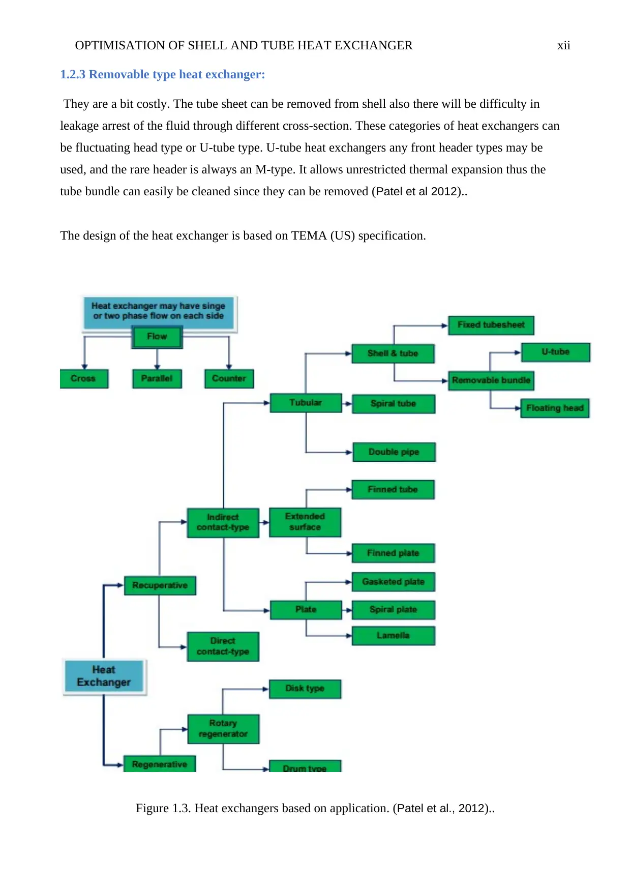
1.2.3 Removable type heat exchanger:
They are a bit costly. The tube sheet can be removed from shell also there will be difficulty in
leakage arrest of the fluid through different cross-section. These categories of heat exchangers can
be fluctuating head type or U-tube type. U-tube heat exchangers any front header types may be
used, and the rare header is always an M-type. It allows unrestricted thermal expansion thus the
tube bundle can easily be cleaned since they can be removed (Patel et al 2012)..
The design of the heat exchanger is based on TEMA (US) specification.
Figure 1.3. Heat exchangers based on application. (Patel et al., 2012)..
⊘ This is a preview!⊘
Do you want full access?
Subscribe today to unlock all pages.
Trusted by 1+ million students worldwide
1 out of 45
Related Documents


Your All-in-One AI-Powered Toolkit for Academic Success.
+13062052269
info@desklib.com
Available 24*7 on WhatsApp / Email
![[object Object]](/_next/static/media/star-bottom.7253800d.svg)
Unlock your academic potential
Copyright © 2020–2026 A2Z Services. All Rights Reserved. Developed and managed by ZUCOL.