In-Depth Report: OSI Layers, Protocols and Mobile Cloud Networks
VerifiedAdded on 2023/04/21
|22
|3449
|73
Report
AI Summary
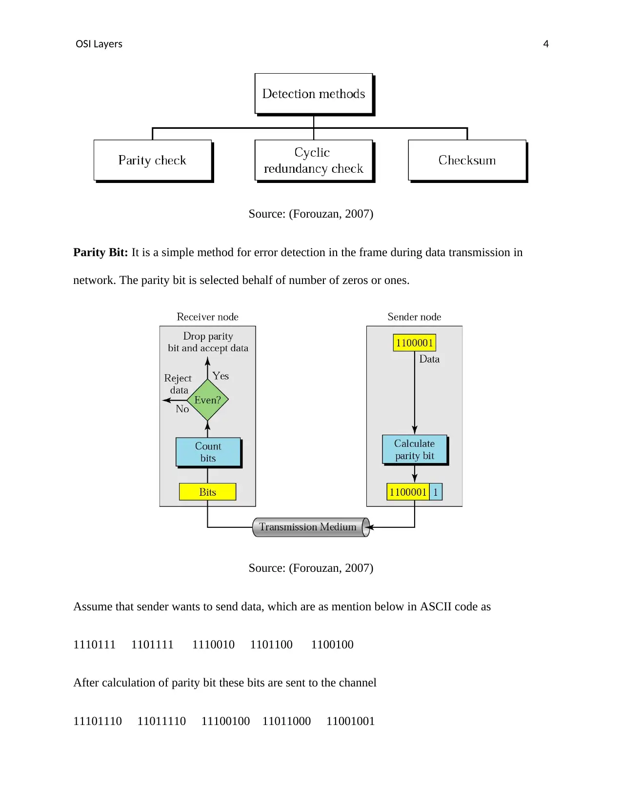
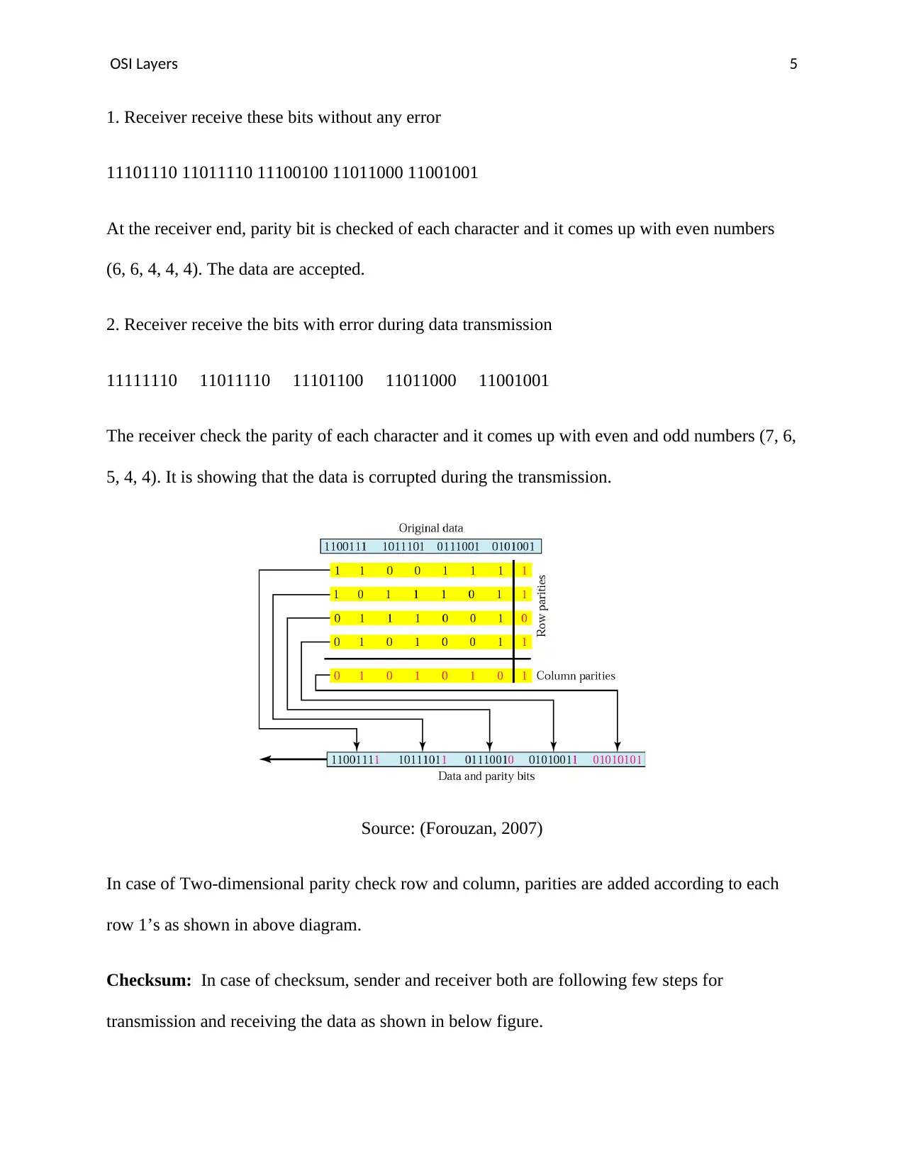
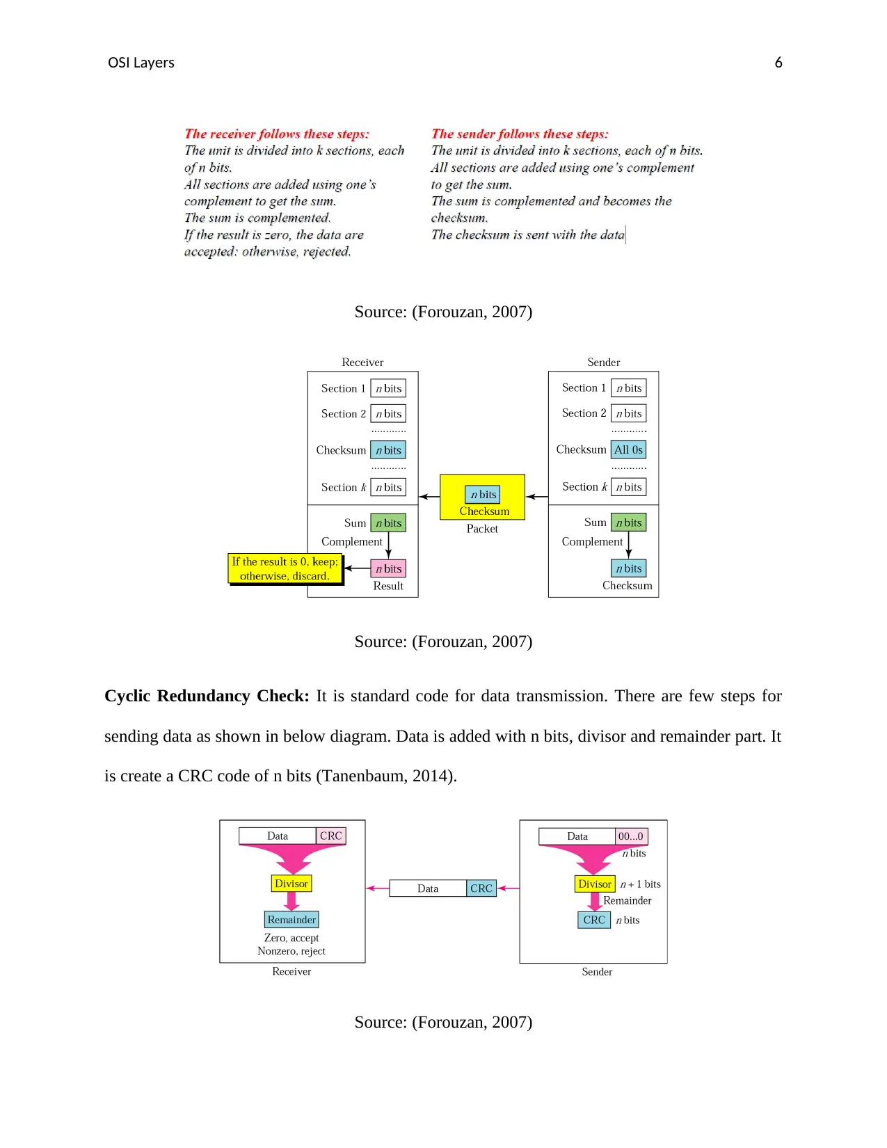
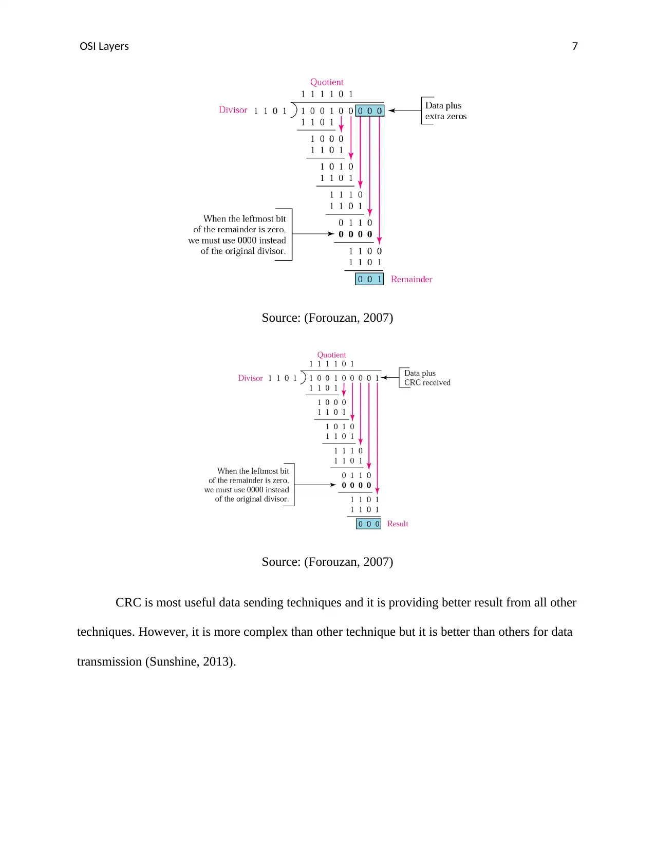
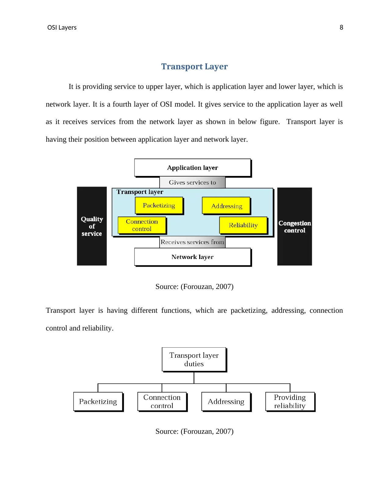
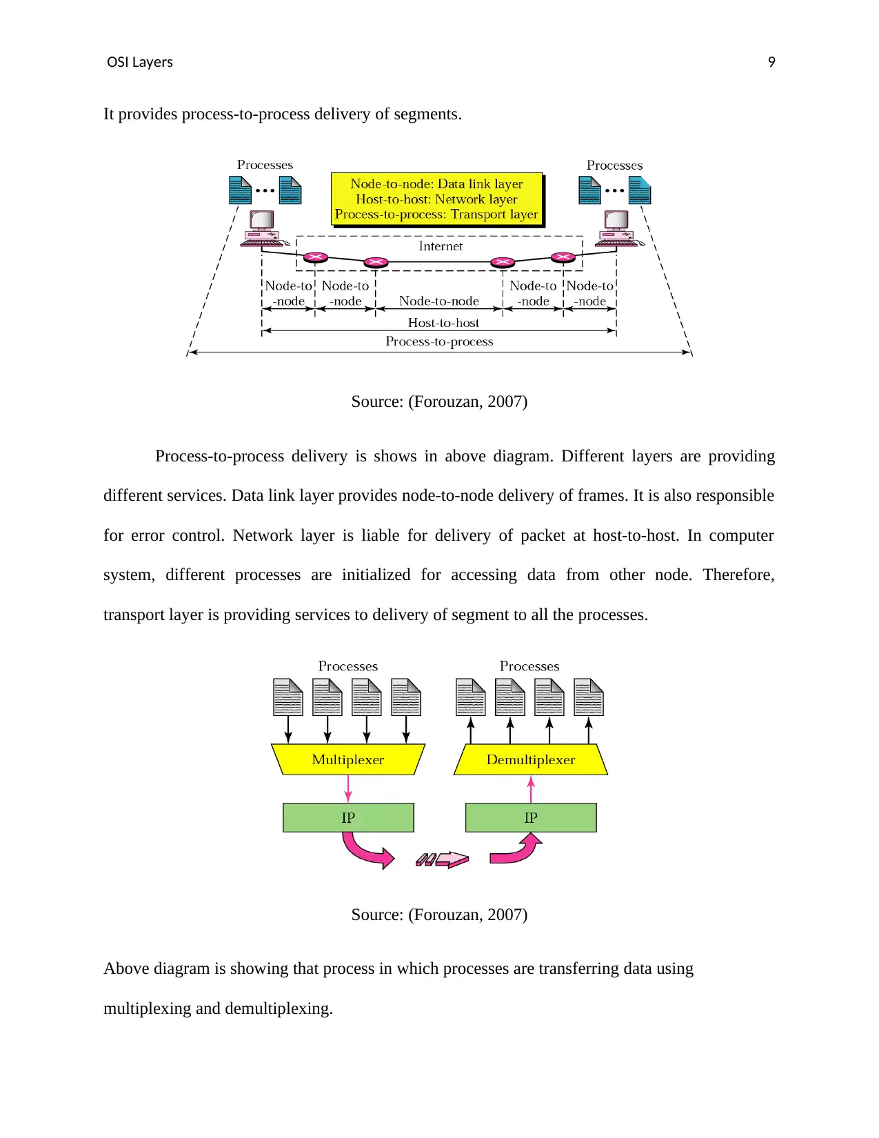
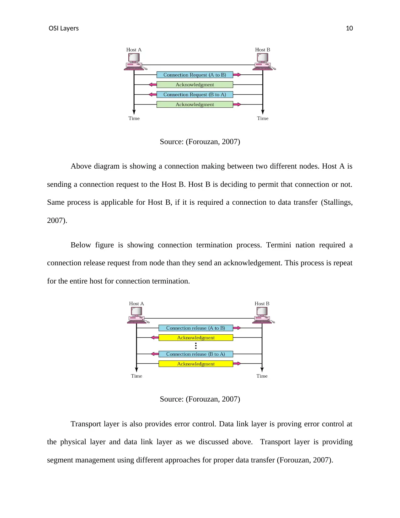
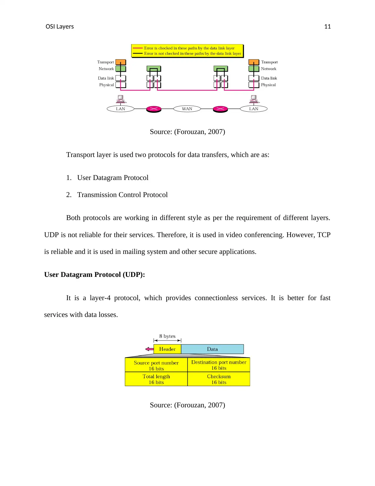
This report provides an in-depth analysis of the Data Link and Transport layers within the OSI model, focusing on their functions, protocols, and error control mechanisms. The Data Link layer's framing methods, including character count, character stuffing, bit stuffing, and physical layer coding violations, are discussed, along with error detection techniques like parity bits, checksums, and Cyclic Redundancy Check (CRC). The Transport layer's role in process-to-process delivery, connection control, and reliability is examined, highlighting the differences between UDP and TCP protocols. Furthermore, the report explores the integration of mobile and cloud networks, addressing challenges faced by cellular networks and the potential of virtualization and cloud computing to optimize network resources and reduce operational expenses. The Mobile Cloud Networking (MCN) project is also mentioned as an EU-funded research initiative focused on integrating cellular networks and cloud computing using network function virtualization. Desklib offers this document and many others, providing students with valuable resources for their studies.

Running Head: OSI LAYERS 0
OSI Layers
Report
Student name
OSI Layers
Report
Student name
Paraphrase This Document
Need a fresh take? Get an instant paraphrase of this document with our AI Paraphraser

OSI Layers 1
Table of Contents
Data link layer..................................................................................................................................2
Framing:.......................................................................................................................................2
Error Control:...............................................................................................................................3
Transport Layer...............................................................................................................................9
Mobile and Cloud network............................................................................................................16
Cloud-Based RAN:....................................................................................................................17
Reference.......................................................................................................................................19

OSI Layers 2
Data link layer
It was designed for error free transmission between different nodes in a network. It is
second layer of Open system Interconnection (OSI) model (Chen, Hsu, & Cheng, 2014). This
layer breaks the datagrams and converts them into frames, which are ready for transfer into the
network. It is called framing. It has two main functions, which are as:
1. Providing reliable data transfer
2. Flow control
Framing:
Physical layer is used for transferring bits without any structure. The responsibility of the
data link layers creates and recognizes frame boundaries. It is a process, in which adding of bits
in the beginning and end of the frame for recognition. It used four methods for framing, which
are widely used are:
1. Character count
2. Character stuffing
3. Bit stuffing
4. Physical layer coding violations
All these methods are used for frame transmission.
Character Count: It is using a header field in which mention number of characters in the frame.
Destination node is checked this field and separate that frame. It is used for finding end of the
frame. It is having a huge disadvantage that if header is missing because of transmissions then no
⊘ This is a preview!⊘
Do you want full access?
Subscribe today to unlock all pages.

Trusted by 1+ million students worldwide

OSI Layers 3
one can find end of the frame. Therefore, this method is rarely used for data transmission
(Cowley, 2012).
Character Stuffing: This method is used American Standard Code for Informational
Interchange (ASCII) character sequence in starting and ending of the frame. This method is used
for overcomes the disadvantages of character count method. It used Data Link Escape (DLE)
STX and DLE ETX in starting and ending of frame. If destination is missing the synchronization
bits then it is used DLE STX and DLE ETX for finding the frame. However, it is having an
insertion and deletion time for stuffing of character (Dye, McDonald, & Rufi, 2007).
Bit stuffing: this is third method of framing. It allows data frame to contain arbitrary number of
bits, which is a character code. It is inserted in the starting and ending of the frame. It is also
known as flag byte in a frame such as 01111110. This is a way to send and receive frames
between different nodes in a network (Forouzan, 2007).
Physical layer coding violations: This is a method to encode and decode the bits using some
redundancy, such as Cyclic Redundancy Check (CRC), CRC-16 and CRC-32. It is used for
marking frame boundaries (Kenneth C. Mansfield & Antonakos, 2009).
Error Control:
Physical layer is not providing any grantee for error free transmission. The DLL is
responsible for error detection as well as error correction in data transfer between different
nodes. Most of the network model is using checksum for error control. Checksum is a compute
bit, which are used to find error in the frame. Checksums are having two types, which are error
detecting, and error detecting and correcting (Mitchell, 2018).
These are few methods of error detection:
Paraphrase This Document
Need a fresh take? Get an instant paraphrase of this document with our AI Paraphraser

OSI Layers 4
Source: (Forouzan, 2007)
Parity Bit: It is a simple method for error detection in the frame during data transmission in
network. The parity bit is selected behalf of number of zeros or ones.
Source: (Forouzan, 2007)
Assume that sender wants to send data, which are as mention below in ASCII code as
1110111 1101111 1110010 1101100 1100100
After calculation of parity bit these bits are sent to the channel
11101110 11011110 11100100 11011000 11001001
Source: (Forouzan, 2007)
Parity Bit: It is a simple method for error detection in the frame during data transmission in
network. The parity bit is selected behalf of number of zeros or ones.
Source: (Forouzan, 2007)
Assume that sender wants to send data, which are as mention below in ASCII code as
1110111 1101111 1110010 1101100 1100100
After calculation of parity bit these bits are sent to the channel
11101110 11011110 11100100 11011000 11001001

OSI Layers 5
1. Receiver receive these bits without any error
11101110 11011110 11100100 11011000 11001001
At the receiver end, parity bit is checked of each character and it comes up with even numbers
(6, 6, 4, 4, 4). The data are accepted.
2. Receiver receive the bits with error during data transmission
11111110 11011110 11101100 11011000 11001001
The receiver check the parity of each character and it comes up with even and odd numbers (7, 6,
5, 4, 4). It is showing that the data is corrupted during the transmission.
Source: (Forouzan, 2007)
In case of Two-dimensional parity check row and column, parities are added according to each
row 1’s as shown in above diagram.
Checksum: In case of checksum, sender and receiver both are following few steps for
transmission and receiving the data as shown in below figure.
⊘ This is a preview!⊘
Do you want full access?
Subscribe today to unlock all pages.

Trusted by 1+ million students worldwide

OSI Layers 6
Source: (Forouzan, 2007)
Cyclic Redundancy Check: It is standard code for data transmission. There are few steps for
sending data as shown in below diagram. Data is added with n bits, divisor and remainder part. It
is create a CRC code of n bits (Tanenbaum, 2014).
Source: (Forouzan, 2007)
Cyclic Redundancy Check: It is standard code for data transmission. There are few steps for
sending data as shown in below diagram. Data is added with n bits, divisor and remainder part. It
is create a CRC code of n bits (Tanenbaum, 2014).
Source: (Forouzan, 2007)
Paraphrase This Document
Need a fresh take? Get an instant paraphrase of this document with our AI Paraphraser

OSI Layers 7
Source: (Forouzan, 2007)
CRC is most useful data sending techniques and it is providing better result from all other
techniques. However, it is more complex than other technique but it is better than others for data
transmission (Sunshine, 2013).
Source: (Forouzan, 2007)
CRC is most useful data sending techniques and it is providing better result from all other
techniques. However, it is more complex than other technique but it is better than others for data
transmission (Sunshine, 2013).

OSI Layers 8
Transport Layer
It is providing service to upper layer, which is application layer and lower layer, which is
network layer. It is a fourth layer of OSI model. It gives service to the application layer as well
as it receives services from the network layer as shown in below figure. Transport layer is
having their position between application layer and network layer.
Source: (Forouzan, 2007)
Transport layer is having different functions, which are packetizing, addressing, connection
control and reliability.
Source: (Forouzan, 2007)
⊘ This is a preview!⊘
Do you want full access?
Subscribe today to unlock all pages.

Trusted by 1+ million students worldwide

OSI Layers 9
It provides process-to-process delivery of segments.
Source: (Forouzan, 2007)
Process-to-process delivery is shows in above diagram. Different layers are providing
different services. Data link layer provides node-to-node delivery of frames. It is also responsible
for error control. Network layer is liable for delivery of packet at host-to-host. In computer
system, different processes are initialized for accessing data from other node. Therefore,
transport layer is providing services to delivery of segment to all the processes.
Source: (Forouzan, 2007)
Above diagram is showing that process in which processes are transferring data using
multiplexing and demultiplexing.
Paraphrase This Document
Need a fresh take? Get an instant paraphrase of this document with our AI Paraphraser

OSI Layers 10
Source: (Forouzan, 2007)
Above diagram is showing a connection making between two different nodes. Host A is
sending a connection request to the Host B. Host B is deciding to permit that connection or not.
Same process is applicable for Host B, if it is required a connection to data transfer (Stallings,
2007).
Below figure is showing connection termination process. Termini nation required a
connection release request from node than they send an acknowledgement. This process is repeat
for the entire host for connection termination.
Source: (Forouzan, 2007)
Transport layer is also provides error control. Data link layer is proving error control at
the physical layer and data link layer as we discussed above. Transport layer is providing
segment management using different approaches for proper data transfer (Forouzan, 2007).
Source: (Forouzan, 2007)
Above diagram is showing a connection making between two different nodes. Host A is
sending a connection request to the Host B. Host B is deciding to permit that connection or not.
Same process is applicable for Host B, if it is required a connection to data transfer (Stallings,
2007).
Below figure is showing connection termination process. Termini nation required a
connection release request from node than they send an acknowledgement. This process is repeat
for the entire host for connection termination.
Source: (Forouzan, 2007)
Transport layer is also provides error control. Data link layer is proving error control at
the physical layer and data link layer as we discussed above. Transport layer is providing
segment management using different approaches for proper data transfer (Forouzan, 2007).

OSI Layers 11
Source: (Forouzan, 2007)
Transport layer is used two protocols for data transfers, which are as:
1. User Datagram Protocol
2. Transmission Control Protocol
Both protocols are working in different style as per the requirement of different layers.
UDP is not reliable for their services. Therefore, it is used in video conferencing. However, TCP
is reliable and it is used in mailing system and other secure applications.
User Datagram Protocol (UDP):
It is a layer-4 protocol, which provides connectionless services. It is better for fast
services with data losses.
Source: (Forouzan, 2007)
⊘ This is a preview!⊘
Do you want full access?
Subscribe today to unlock all pages.

Trusted by 1+ million students worldwide
1 out of 22
Related Documents
Your All-in-One AI-Powered Toolkit for Academic Success.
+13062052269
info@desklib.com
Available 24*7 on WhatsApp / Email
Unlock your academic potential
Copyright © 2020–2025 A2Z Services. All Rights Reserved. Developed and managed by ZUCOL.


