ME5011 Thermofluids: Preliminary Design of Overhead Crane Girder
VerifiedAdded on ย 2023/04/20
|13
|1693
|411
Report
AI Summary
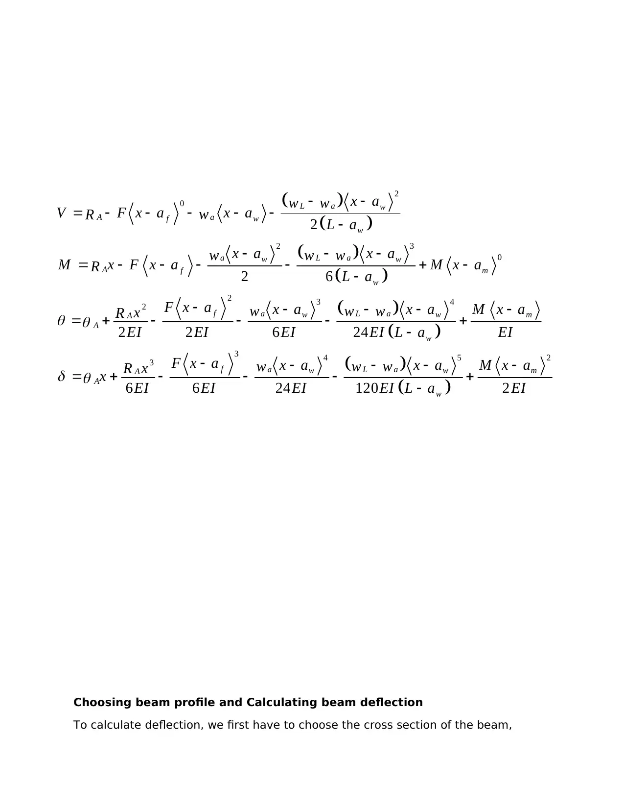
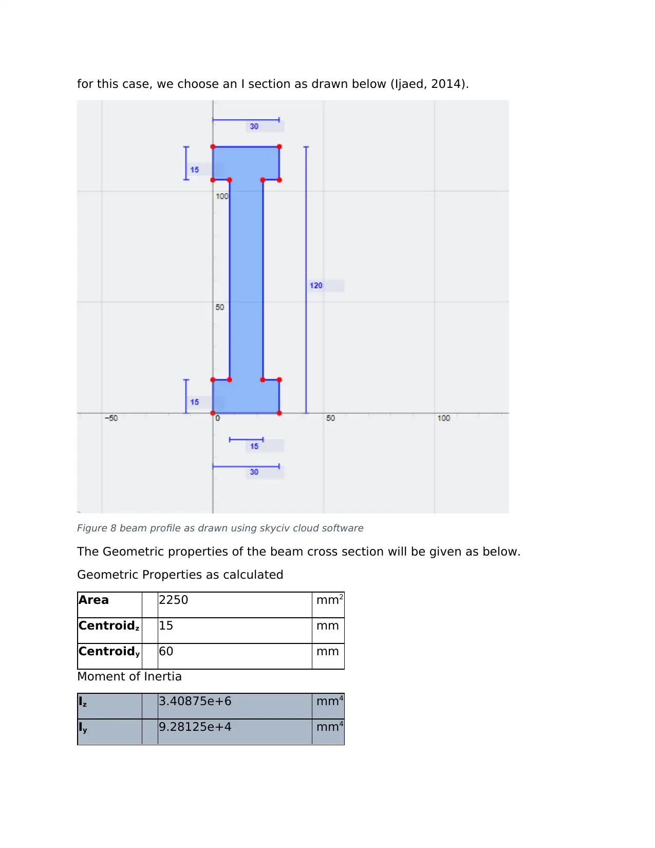
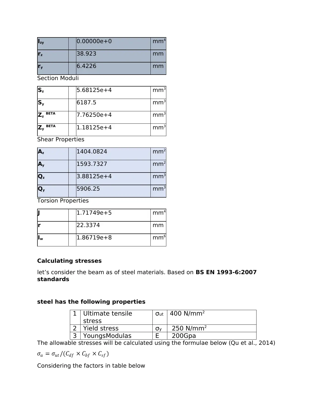
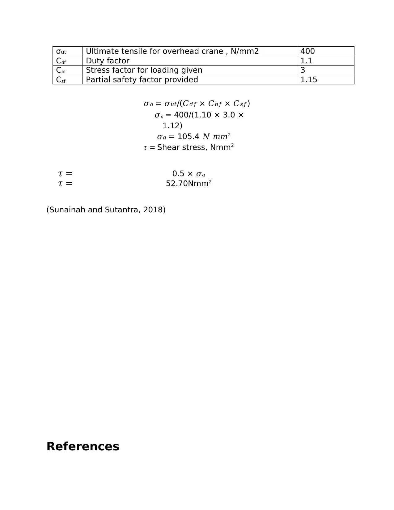
This report presents the preliminary design calculations for a single overhead traveling crane, addressing the design of a single girder. The report includes calculations for N-Q-M diagrams and familiarization with single girder overhead cranes, their design, and the standards used in design. Key considerations include a 6m crane span, a 3.2-tonne lifting capacity, and a 600mm wheelbase for the trolley. The calculations cover bending moments, shear force, and deflection, with considerations for a simply supported beam and a moving point load. The report also details the selection of a beam profile (I-section), geometric properties, and stress calculations based on BS EN 1993-6:2007 standards, ensuring the design meets safety factors and allowable stress limits. References to relevant academic sources and engineering standards are provided to support the design process.
Contribute Materials
Your contribution can guide someoneโs learning journey. Share your
documents today.

Preliminary design calculations for single overhead travelling crane
Student name
Student level or class
Lecturers name
School name
School location
Date of submission
Student name
Student level or class
Lecturers name
School name
School location
Date of submission
Secure Best Marks with AI Grader
Need help grading? Try our AI Grader for instant feedback on your assignments.

1.0 Introduction
An overhead crane is a type of crane , majorly found in heavy industrial
environments, usually referred to as a bridge crane. An overhead crane comprises
of elevons spanning the gap with a traveling bridge. A hoist, a crane's lifting
component, crosses the bridge. The crane is called a gantry crane (USA, ASME B30
series) or a goliath crane (UK, BS 466) if the bridge is rigidly supported on two or
more legs running on a fixed rail at ground level. The bridge can go down the
runways. The crane's lifting element is the hoist that is attached properly to a
trolley. The trolley is allowed to travel along the bridge. Such girders are found in
heavy industrial environments, factories and manufacturing plants, serving the
purpose of transporting (lifting and moving) objects within a given footprint from
one area to another. The bridge itself is a steel structure that is produced by
properly welding together steel plates. A commonly available rolled steel beam can
also be used, however. In any case, a preliminary design and assessment is
necessary to get a quick and easy first impression of the bridge girder cross
parameters (Behera, 2012).
Figure 1 single girder example (Indiamart, 2019)
2.0 Aims
The main goal of this paper is to present the following.
๏ท Perform calculations for single overhead girder design
๏ท To practice calculations of N-Q-M diagrams
๏ท To be familiar with single girder overhead cranes, their design and standards
used in design
3.considerations
The crane is defined by the parameters define below
๏ท The span of the crane will be 6m and with lifting capacity of 3.2 tones
๏ท Wheel base for trolley is 600m with load distribution of 40% to 60%, distance
of trolley to beam end should be 100mm, at most. The beam is to be
considered as single supported.

4. calculations for preliminary design
Considering the maximum displacement for vertical movement to be 20mm, and
developed stress lower than the yield stress. The safety factor should be 1.15,
with frequency greater than 1.2 Hertz
Consider the girder frame span of 6m as shown,
Figure 2 illustration of simply supported girder beam, the point load is moving, the beam is assumed
as simply supported
To find maximum bending moments, consider the formulae below
Bending moments= perpendicular force รdistance
Bending moment for the beam at span of 3 meters calculated as
Bm= Frร d
Bm= 32kN ร 3M
BM = 96 kN-M
direction of moments

BM= -96kM
(Tian, Zhang and Sun, 2012)
Bending moment for the beam at span of 3 meters calculated based on moving
support
Bm= Frร d
Bm= 32kN ร 3M
BM = 96 kN-M
BM = 96 kN-M
The position of maximum bending moments is at 3m from both ends. True
for simple supported beam
Figure 3 for the beam above, its Bm diagram will be plotted as follows
Secure Best Marks with AI Grader
Need help grading? Try our AI Grader for instant feedback on your assignments.

Distanc
e 0 1.5 3 4.5 6
Bendin
g
mome
nt
0 48
kNM
96
kNM
48
kNM 0
0 1 2 3 4 5 6 7
0
20
40
60
80
100
120
Bending moment
Figure 4 bending moment diagram plot, maximum moments at point 3m along the beam span
Calculating the shear force
Considerations to be made are as follows,
๏ท Simply supported beam
๏ท The point load is moving
๏ท No fixed loads at any point since the trolley is moving
Shear force at point 0
Force = 0
Force at 0.1m is 0N
Shear Force at 1 M= 32kN
Shear force at 3M = 32 kN
Shearing force will therefore be equal along the beam since the trolley has fixed
load of 3.2tonnes, its moving and at no pint will it be in 2 points.

Figure 5 showing maximum shear and moments location, (mithalino.com, 2019)
The information retrieved from mithalino.com website (2019) strength of materials
moving loads explain that for a single moving load, the maximum shear force of a
simply supported beam occurs very near the support. Based on trolley description,
the nearest distance the trolley comes to the support is 100mm, therefore
maximum shear force occurs at point 100mm in both ends(Mathalino.com, 2019).
Figure 6 maximum shear forces at point 100mm from supports, diagram drawn using skyciv cloud
engineering software

Figure 7 SFD diagram considering the trolleys at maximum point, other points not drawn
The shear force cannot be added since the trolley cannot be in 2 positions at the
same time, to calculate the shear force at each point, we assume a movable point
load for the beam as 32kN
Distan
ce 0 0.1 1.5 3 4.5 5.9 6
Bendin
g
mome
nt
0 kNM
32
kNM 32
kNM
32
kNM
32
kNM
32
kNM 0
The shear force cannot be added since the trolley cannot be in 2 positions at the
same time, to calculate the shear force at each point, we assume a movable point
load for the beam as 32kN
Distan
ce 0 0.1 1.5 3 4.5 5.9 6
Bendin
g
mome
nt
0 kNM
32
kNM 32
kNM
32
kNM
32
kNM
32
kNM 0
Paraphrase This Document
Need a fresh take? Get an instant paraphrase of this document with our AI Paraphraser

0 1 2 3 4 5 6 7
0
5
10
15
20
25
30
35
shear force
Deflection position
The location of maximum deflection is at the midspan of the girder bridge
Max deflection location = 3m from supports
Deflection plots have been provided in excel files
0
500
1000
1500
2000
2500
3000
3500
4000
4500
5000
5500
6000
6500
7000
7500
8000
8500
9000
9500
10000
-200000.0
-150000.0
-100000.0
-50000.0
0.0
50000.0
100000.0
150000.0
200000.0
Deflection
Distance from left end of beam (mm)
Deflection (mcrons)
0
5
10
15
20
25
30
35
shear force
Deflection position
The location of maximum deflection is at the midspan of the girder bridge
Max deflection location = 3m from supports
Deflection plots have been provided in excel files
0
500
1000
1500
2000
2500
3000
3500
4000
4500
5000
5500
6000
6500
7000
7500
8000
8500
9000
9500
10000
-200000.0
-150000.0
-100000.0
-50000.0
0.0
50000.0
100000.0
150000.0
200000.0
Deflection
Distance from left end of beam (mm)
Deflection (mcrons)

Choosing beam profile and Calculating beam deflection
To calculate deflection, we first have to choose the cross section of the beam,
๏จ ๏ฉ
๏จ ๏ฉ
๏จ ๏ฉ
๏จ ๏ฉ
๏จ ๏ฉ
๏จ ๏ฉ
๏จ ๏ฉ
๏จ ๏ฉ
2
0
2 3
0
2 3 4
2
3 4 5 2
3
2
2 6
2 2 6 24
6 6 24 120 2
L a w
A af w
w
a L aw w
A f m
w
f a L aw w mA
A
w
f a L aw w mA
A
w
x aw w
V F x a x awR L a
x a x aw w w
M x F x a M x aR L a
F x a x a x a M x aw w wxR
EI EI EI EI L a EI
F x a x a x a M x aw w wxR
x EI EI EI EI L a
๏ฑ ๏ฑ
๏ค ๏ฑ
๏ญ ๏ญ
๏ฝ ๏ญ ๏ญ ๏ญ ๏ญ ๏ญ ๏ญ
๏ญ ๏ญ ๏ญ
๏ฝ ๏ญ ๏ญ ๏ญ ๏ญ ๏ซ ๏ญ
๏ญ
๏ญ ๏ญ ๏ญ ๏ญ ๏ญ
๏ฝ ๏ซ ๏ญ ๏ญ ๏ญ ๏ซ
๏ญ
๏ญ ๏ญ ๏ญ ๏ญ ๏ญ
๏ฝ ๏ซ ๏ญ ๏ญ ๏ญ ๏ซ
๏ญ EI

for this case, we choose an I section as drawn below (Ijaed, 2014).
Figure 8 beam profile as drawn using skyciv cloud software
The Geometric properties of the beam cross section will be given as below.
Geometric Properties as calculated
Area 2250 mm2
Centroidz 15 mm
Centroidy 60 mm
Moment of Inertia
Iz 3.40875e+6 mm4
Iy 9.28125e+4 mm4
Figure 8 beam profile as drawn using skyciv cloud software
The Geometric properties of the beam cross section will be given as below.
Geometric Properties as calculated
Area 2250 mm2
Centroidz 15 mm
Centroidy 60 mm
Moment of Inertia
Iz 3.40875e+6 mm4
Iy 9.28125e+4 mm4
Secure Best Marks with AI Grader
Need help grading? Try our AI Grader for instant feedback on your assignments.

Izy 0.00000e+0 mm4
rz 38.923 mm
ry 6.4226 mm
Section Moduli
Sz 5.68125e+4 mm3
Sy 6187.5 mm3
Zz BETA 7.76250e+4 mm3
Zy BETA 1.18125e+4 mm3
Shear Properties
Az 1404.0824 mm2
Ay 1593.7327 mm2
Qz 3.88125e+4 mm3
Qy 5906.25 mm3
Torsion Properties
J 1.71749e+5 mm4
r 22.3374 mm
Iw 1.86719e+8 mm6
Calculating stresses
letโs consider the beam as of steel materials. Based on BS EN 1993-6:2007
standards
steel has the following properties
1 Ultimate tensile
stress
ฯut 400 N/mm2
2 Yield stress ฯy 250 N/mm2
3 YoungsModulas E 200Gpa
The allowable stresses will be calculated using the formulae below (Qu et al., 2014)
Considering the factors in table below

ฯut Ultimate tensile for overhead crane , N/mm2 400
Cdf Duty factor 1.1
Cbf Stress factor for loading given 3
Csf Partial safety factor provided 1.15
๐๐ = ๐๐ข๐ก/(๐ถ๐๐ ร ๐ถ๐๐ ร ๐ถ๐ ๐)
๐๐ = 400/(1.10 ร 3.0 ร
1.12)
๐ = 105.4 ๐ ๐๐2
Shear stress, Nmm2
0.5 ร ๐
52.70Nmm2
(Sunainah and Sutantra, 2018)
References
Cdf Duty factor 1.1
Cbf Stress factor for loading given 3
Csf Partial safety factor provided 1.15
๐๐ = ๐๐ข๐ก/(๐ถ๐๐ ร ๐ถ๐๐ ร ๐ถ๐ ๐)
๐๐ = 400/(1.10 ร 3.0 ร
1.12)
๐ = 105.4 ๐ ๐๐2
Shear stress, Nmm2
0.5 ร ๐
52.70Nmm2
(Sunainah and Sutantra, 2018)
References

Behera, A. (2012). Electric Overhead Travelling Crane Model.
Saarbruฬcken: LAP LAMBERT Academic Publishing.
European, U. (2019). Eurocode 3 - Design of steel structures - Part
6: Crane supporting structures. 3rd ed. European union: European
Standard.
Ijaed (2014). Design, Analysis and Optimization of Overhead Crane
Girder. International Journal of Advance Engineering and Research
Development, 1(06).
Mathalino.com. (2019). Moving Loads | Strength of Materials Review.
[online] Available at:
https://www.mathalino.com/reviewer/mechanics-and-strength-of-
materials/moving-loads [Accessed 29 Mar. 2019].
Qu, X., Xu, G., Fan, X. and Bi, X. (2014). Intelligent optimization
methods for the design of an overhead travelling crane. Chinese
Journal of Mechanical Engineering, 28(1), pp.187-196.
Sunainah, A. and Sutantra, I. (2018). Analisis dan Redesign
Kekuatan Struktur pada Girder Overhead Crane 6.3 Ton. Jurnal
Teknik ITS, 7(1).
Tian, G., Zhang, S. and Sun, S. (2012). The Optimization Design of
Overhead Traveling Crane's Box Girder. Advanced Materials
Research, 538-541, pp.2850-2855.
1 out of 13

Your All-in-One AI-Powered Toolkit for Academic Success.
ย +13062052269
info@desklib.com
Available 24*7 on WhatsApp / Email
Unlock your academic potential
ยฉ 2024 ย | ย Zucol Services PVT LTD ย | ย All rights reserved.