Passive Radar Systems: Modeling Opportunity Radio Sources - TU Campus
VerifiedAdded on 2023/05/28
|25
|4954
|88
Project
AI Summary
This project delves into the analysis and modeling of passive radar systems, leveraging opportunity radio sources such as WLAN and geosynchronous satellites. The report begins with an introduction to passive radar, including its advantages and processing steps. It then explores various WLAN sources, including Wi-Fi, WiMAX, Bluetooth, and others, discussing their operational characteristics. The project also investigates geosynchronous satellites, particularly those transmitting television signals, and identifies relevant signals around the TU campus. The core of the project involves the design of radio receivers equipped with antennas to cover both the objects to be detected and the illumination zones of the radio sources. Furthermore, the report uses MATLAB to simulate a bistatic radar system, including considerations for bistatic scattering from rain. Design recommendations for the bistatic radar are also provided. The report concludes by summarizing the findings and highlighting the potential applications of passive radar systems in real-world scenarios like weather monitoring.

PASSIVE RADAR SYSTEMS
BY
Course
Instructor
Institution
Location
Date
ii
BY
Course
Instructor
Institution
Location
Date
ii
Paraphrase This Document
Need a fresh take? Get an instant paraphrase of this document with our AI Paraphraser

ABSTRACT
In the coming years, passive radars has been viewed to be the missing ingredient to active
radar. Passive radar gives an important operational advantage they are hard or impossible to
locate. This type of radar can never be jammed due to the fact that zero waves are emitted in
its operation. Passive radar mainly employs the services of digital TV and radio frequencies
as the carrier waves thereby avoiding its transmitter.
Passive radar system need maximum amount of power in order to compute and some
software for complicated signal processing. The system uses 20 transmitters with a
combination of digital and VHF frequencies on a high performing on-board computer.
iii
TABLE OF CONTENTS
Contents
ABSTRACT.............................................................................................................................iii
TABLE OF CONTENTS.........................................................................................................4
LIST OF FIGURES.................................................................................................................5
LIST OF ABBREVIATIONS..................................................................................................6
LIST OF SYMBOLS................................................................................................................7
INTRODUCTION....................................................................................................................8
PASSIVE RADAR SYSTEMS................................................................................................9
Processing Steps used by Passive Radar System...............................................................9
WLAN.....................................................................................................................................12
Standard WLAN sources...................................................................................................12
GEOSYNCHRONOUS SATELLITES................................................................................14
Types of geosynchronous signals around TU...................................................................14
BISTATIC RADAR...............................................................................................................15
RADAR EQUATION IN A SIMULATION MODEL IN MATLAB................................16
Simulating a Bistatic Radar in MATLAB........................................................................16
Bistatic scatter for rain......................................................................................................19
DESIGN RECOMMENDATIONS FOR THE BISTATIC RADAR................................20
CONCLUSION.......................................................................................................................21
REFERENCES.......................................................................................................................21
⊘ This is a preview!⊘
Do you want full access?
Subscribe today to unlock all pages.
Trusted by 1+ million students worldwide
LIST OF FIGURES
Figure 2: An example of Passive Radar System 9
Figure 2.1: Processing steps used in passive radar system 10
Figure 6.1: MATLAB model showing passive radar with 2 targets 17
Figure 6.2: Simulation of a Bistatic Passive Radar 19
Figure 6.3: Bistatic scattering from rain 20
5
Figure 2: An example of Passive Radar System 9
Figure 2.1: Processing steps used in passive radar system 10
Figure 6.1: MATLAB model showing passive radar with 2 targets 17
Figure 6.2: Simulation of a Bistatic Passive Radar 19
Figure 6.3: Bistatic scattering from rain 20
5
Paraphrase This Document
Need a fresh take? Get an instant paraphrase of this document with our AI Paraphraser
LIST OF ABBREVIATIONS
WLAN – Wireless Local Area Network
WiMAX – Worldwide Interoperability for Microwave access
Wi-Fi – Wireless Fidelity
Mbps – Megabits per second
ISP – Internet Service Provider
RF – Radio frequency
DECT – Digital Enhanced Cordless Telecommunication
HIPERLAN – High Performance Radio Local Area Network
DLC – Data Link Control
PAN – Personal Area Network
DVB – Digital Video Broadcasting
TV – Television
GHz - Gigahertz
km – Kilometres
BPR – Bistatic Passive Radar
m/s – metres per second
kW – kilowatts
RCS – Radar Cross Section
IEEE – Institute of Electrical and Electronics Engineers
CFAR – Constant False Alarm Rate
ISM – Industrial, Scientific Medical
ATM – Air Traffic Management
LNB – Low Noise Block
FM – Frequency Modulated
UHF – Ultra High Frequency
VHF – Very High Frequency
GSM – Global System for Mobile
ULA – Uniform Linear Array
GPS – Global Positioning System
MHz – Megahertz
6
LIST OF SYMBOLS
Pr – Received power in watts
Pt – Peak transmit power in watts
Gt – Transmit gain
Gr – Receiver gain
λ – Radar operating frequency wavelength in metres
σ – Target’s non-fluctuating radar cross section in square metres
L – General loss factor to account for both system and propagation loss
Rt – Range from transmitter to the target
Rr – Range from receiver to target
K – Boltzmann constants
T – Temperature
Fn – Noise figure
7
⊘ This is a preview!⊘
Do you want full access?
Subscribe today to unlock all pages.
Trusted by 1+ million students worldwide

INTRODUCTION
In majority of the cases, passive radar systems usually do their normal work independent of
broadcasting as well as communication signals. In designing a passive radar, all opportunities
present in the system are there to be exploited. The illumination sources normally have some
properties that dictate the capability of the system in general. This makes the passive radar
become so popular.
It is possible to provide data on weather by using the received radar signals that are reflected
by objects in the atmosphere. It is normal for the passive radar receivers to configure the
signals made available by one or many transmitters.
This report aims at showing the true colours of passive and bistatic radars, and how they can
be applied in real life situations like detecting rain clouds and volume.
8
Paraphrase This Document
Need a fresh take? Get an instant paraphrase of this document with our AI Paraphraser
PASSIVE RADAR SYSTEMS
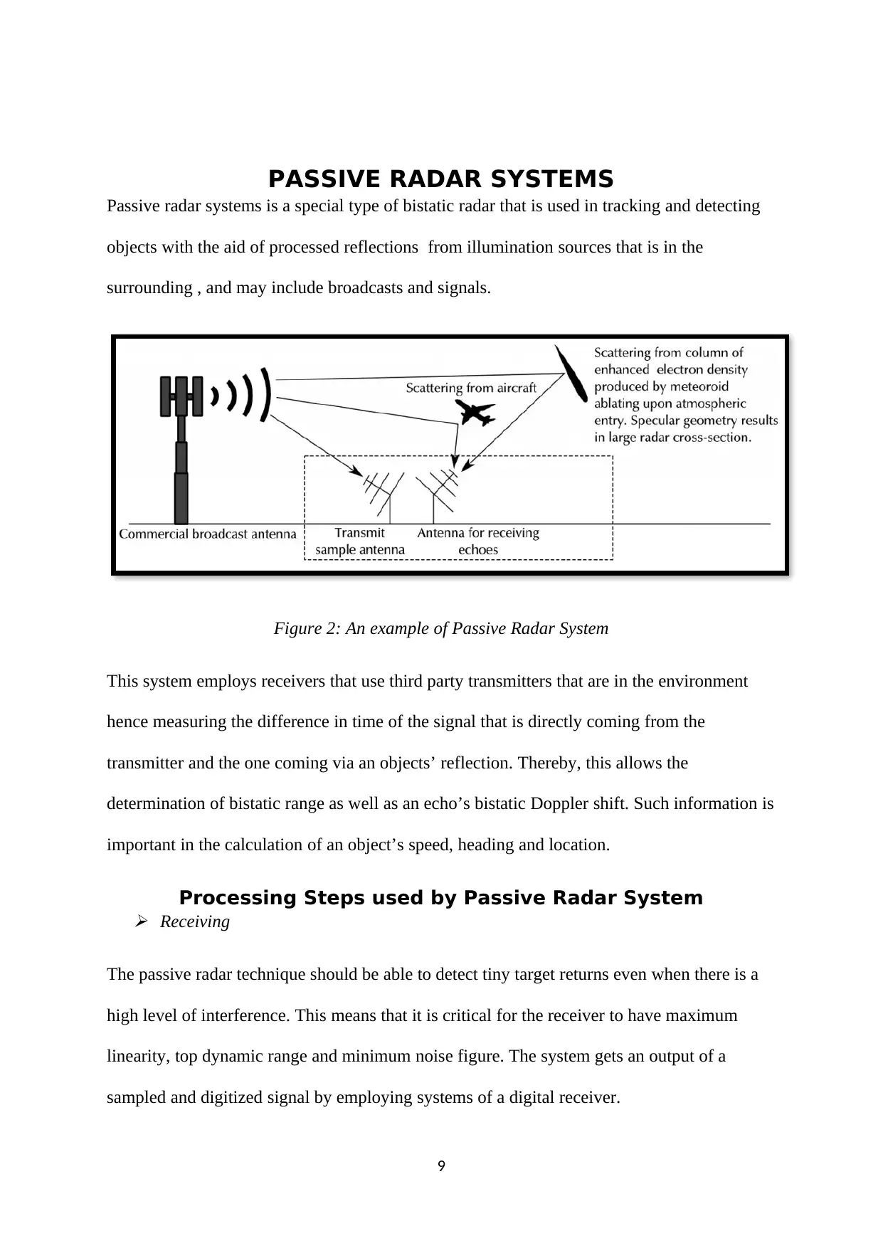
Passive radar systems is a special type of bistatic radar that is used in tracking and detecting
objects with the aid of processed reflections from illumination sources that is in the
surrounding , and may include broadcasts and signals.
Figure 2: An example of Passive Radar System
This system employs receivers that use third party transmitters that are in the environment
hence measuring the difference in time of the signal that is directly coming from the
transmitter and the one coming via an objects’ reflection. Thereby, this allows the
determination of bistatic range as well as an echo’s bistatic Doppler shift. Such information is
important in the calculation of an object’s speed, heading and location.
Processing Steps used by Passive Radar System
Receiving
The passive radar technique should be able to detect tiny target returns even when there is a
high level of interference. This means that it is critical for the receiver to have maximum
linearity, top dynamic range and minimum noise figure. The system gets an output of a
sampled and digitized signal by employing systems of a digital receiver.
9
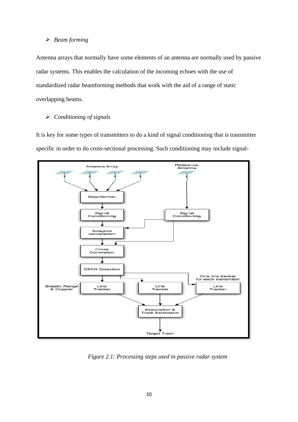
Beam forming
Antenna arrays that normally have some elements of an antenna are normally used by passive
radar systems. This enables the calculation of the incoming echoes with the use of
standardized radar beamforming methods that work with the aid of a range of static
overlapping beams.
Conditioning of signals
It is key for some types of transmitters to do a kind of signal conditioning that is transmitter
specific in order to do cross-sectional processing. Such conditioning may include signal-
Figure 2.1: Processing steps used in passive radar system
10
⊘ This is a preview!⊘
Do you want full access?
Subscribe today to unlock all pages.
Trusted by 1+ million students worldwide
-filtering of the maximum quality analogue band pass thereby improving the radar ambiguity
function.
Adaptive filtering
Normally the passive radar system has a limited detection range that is caused by the direct
signal that is comes from a transmitter (Simon, 2008). The adaptive filter takes out the direct
signal via the processed termed as active noise control.
Cross-correlational processing
This is the most important step as it plays the role of the matched filter by providing an
approximation of the bistatic Doppler shift and range of the echo of each target (David B. ,
2008). A lot of signals from digital and analogue broadcasting have some noise effects, and
thereby form a correlation among themselves.
Detecting targets
Cross-correlational surfaces are used in detecting targets with the aid of an adaptive
threshold. In this step it is to use the constant false alarm rate algorithm (CFAR). It is also
normal that the targets are all the returns on top of this surface.
Tracking of lines
Line tracking uses the standardized Kalman filter to track target returns from the single
targets, over a specific period of time. At this stage, there is a rejection of majority of the
false alarms.
Association of tracks and estimating state
11
Paraphrase This Document
Need a fresh take? Get an instant paraphrase of this document with our AI Paraphraser
A configuration that uses a single receiver and transmitter can be used to locate the position
of the target, this is by determining the intersection point of bistatic range ellipse and the
bearing.
WLAN
WLAN refers to a wireless method of distribution that involves two or more devices using
radio frequency of high frequency and commonly have the Internet as the point of access.
Standard WLAN sources
Wi-Fi
This is a protocol (based on 802.11 IEEE network standards) of wireless networking that
enables two or more devices in communicating without the use of internet chords. It basically
operates within a location that is fixed, and is the commonest way of wirelessly
communicating data.
What Wi-Fi requires the most is a device like a phone, router, or computer that can allow the
transmission of wireless signal (Lambert, Radar Networks, 2010). In and around the campus
the popular way in which the Wi-Fi is employed involves the use of Wi-Fi hotspots and ISP.
WiMAX
This involves a technological standard that offers a wireless network for fixed and mobile
connections and is normally long-ranged. It typically exists in two common ways that is,
receivers and base stations. The technology of WiMAX is fixed on the IEEE 802.16 set of
standards.
It basically offers a platform for telephone access, internet access, as well as video and voice
transfer as the transmitters can span several miles of distance and reach up to 30-40 mbps.
Bluetooth
12
This is a technology of wireless communication that is short-ranged thus allowing for the
connection of electronic devices without cables with the aid of a core system (Richard, 2006).
Its RF transceiver works in the unlicensed ISM band centred at 2.4 gigahertz.
The Bluetooth devices enables an individual to have a phone conversation using a headset, or
even synchronizing data from a mobile phone to a computer using a wireless mouse.
Home RF
This involves a home networking standard that has combined the DECT and 802.11b into one
system. It mainly employs a frequency hopping method in order to deliver across a distance
reaching 150 feet at speeds of up to 1.6 mbps.
HIPERLAN
This is a wireless network that provides infrastructure that has low-mobility using data
networks that are cellular based in order to allow a connection to the ATM backbone. It has
various components like the convergence layer, link adaptation, DLC layer as well as
physical layer (Eli, 2004).
It has a data rate reaching 54mbps and achieves the fastest wireless connection.
Zigbee
This involves a low power and data rate as well as close distance ad hoc wireless network. It
is based on a specification of IEEE 802.15.4 standard protocol that creates PANs that have
low-powered digital radios.
DVB
This involves a group of standards that describe digital broadcasting with the use of cable,
terrestrial and satellite infrastructures. It was mainly started to start television broadcasting
13
⊘ This is a preview!⊘
Do you want full access?
Subscribe today to unlock all pages.
Trusted by 1+ million students worldwide
1 out of 25
Your All-in-One AI-Powered Toolkit for Academic Success.
+13062052269
info@desklib.com
Available 24*7 on WhatsApp / Email
![[object Object]](/_next/static/media/star-bottom.7253800d.svg)
Unlock your academic potential
Copyright © 2020–2026 A2Z Services. All Rights Reserved. Developed and managed by ZUCOL.