Competency Demonstration Report - Project
VerifiedAdded on 2020/02/24
|8
|1707
|31
Project
AI Summary
The Competency Demonstration Report details the design and implementation of a Password Protected Lock System using a microcontroller. The project aims to enhance security in various settings by allowing access only to authorized users through a keypad. It outlines the project's objectives, background, and the engineering knowledge applied, including the use of a microcontroller, LCD display, and motor driver IC. The report also discusses challenges faced during implementation and future enhancements, such as integrating fingerprint recognition and attendance tracking.

COMPETENCY
DEMONSTRATION REPORT
Career Episode 2
NAME
DEMONSTRATION REPORT
Career Episode 2
NAME
Paraphrase This Document
Need a fresh take? Get an instant paraphrase of this document with our AI Paraphraser

CE 2.1 Project Information
Name of the project: Password Protected Lock System Designed using Microcontroller
Location of the project: [PLEASE FILL]
Project Duration: [PLEASE FILL]
Organization: [PLEASE FILL]
Role and Designation during the time: [PLEASE FILL]
CE 2.2 Project Background
CE 2.2.1 Characteristics of the project
The system I had designed for this project was the implementation of a security measure
named Password protected Lock System with the help of microcontroller. This has been
designed to bar unauthorized access in homes, offices and large companies. This could also be
coupled up with an attendance system and a time logger which could be used in an office
premises. The door would only open to the person who has the correct pin. After the person has
entered the door will automatically close and the next person has to again input the pin to gain
access. If incorrect pin is given the door will not open to the person. This has been designed
keeping in mind the factor that many a times people often forget their keys at home or drop them
at some place. The project would have a door latch opening mechanism using the authentication
through the password entered through the keypad. The additional buzzer used in the device
would sound when the password is entered incorrectly.

CE 2.2.2 Objectives developed for the project
The main objectives that was followed during the implementation of this project are as
follows:
To implement a digital lock mechanism for doors with a keypad and a LCD display.
To make the digital lock secure and user friendly in nature.
To make the digital lock in such a way so that the locking system can have different pin id
for different individual of the organisation.
CE 2.2.3 My area of work
I had implemented the project on my own to learn more about the implementation of the
microcontrollers and also use a 4X3 keypad for providing user access. The full working model of
the project was completed by me which helped me to learn more about the working procedure of
the different segments of the project.
⊘ This is a preview!⊘
Do you want full access?
Subscribe today to unlock all pages.

Trusted by 1+ million students worldwide

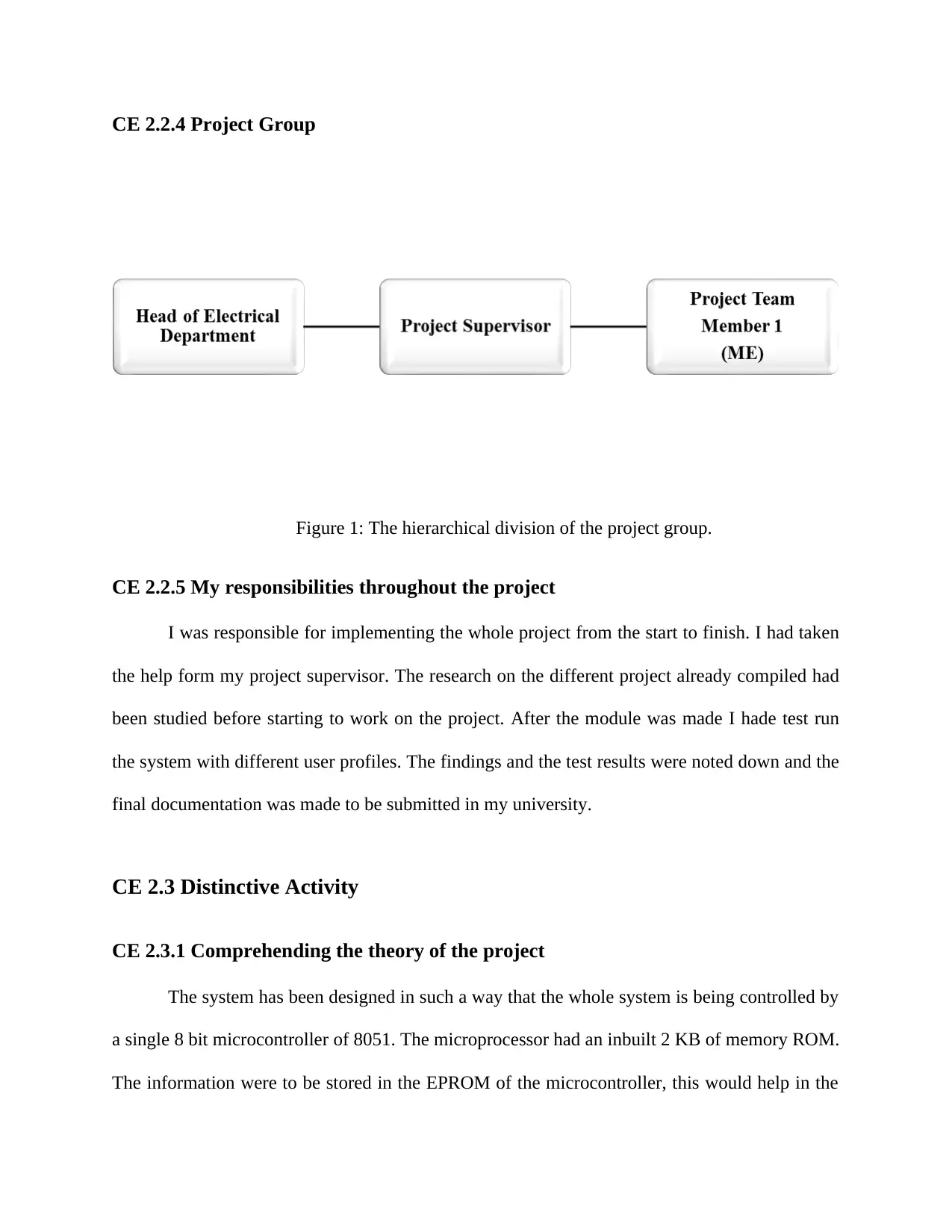
CE 2.2.4 Project Group
Figure 1: The hierarchical division of the project group.
CE 2.2.5 My responsibilities throughout the project
I was responsible for implementing the whole project from the start to finish. I had taken
the help form my project supervisor. The research on the different project already compiled had
been studied before starting to work on the project. After the module was made I hade test run
the system with different user profiles. The findings and the test results were noted down and the
final documentation was made to be submitted in my university.
CE 2.3 Distinctive Activity
CE 2.3.1 Comprehending the theory of the project
The system has been designed in such a way that the whole system is being controlled by
a single 8 bit microcontroller of 8051. The microprocessor had an inbuilt 2 KB of memory ROM.
The information were to be stored in the EPROM of the microcontroller, this would help in the
Paraphrase This Document
Need a fresh take? Get an instant paraphrase of this document with our AI Paraphraser

changing of the stored information when required. The system has been provided with a keypad
which will help the users to input the pin into the system. When the entered password is same as
the password stored in the memory of the system with respect to the user id of the employee then
the door opens for him. If the entered password does not match the password stored in the system
then the door will not open and the LCD will display the message “WRONG PASSOWRD”.
There are two types of relay in the system. One relay would be responsible for the opening the
door on the correct input of the password. The next relay would happen after a certain amount of
time which will be responsible for closing the door. There is a safety lock placed inside the door
which will be used to lock the door from behind when the authorized user has entered through
the door.
CE 2.3.2 Engineering knowledge and skills applied in the project
The engineering knowledge which I have applied for the implementation of this digital
lock system is the basic knowledge of engineering modules. The modules were concerned about
the use of microcontrollers and motor system at the same time. The project has been provided
with help from my supervisor to complete the project.
CE 2.3.3 Accomplishment and task performed
The project consists of five modules which as a whole would be responsible for the
system to work correctly. The different components of the project has been discussed as follows.
Microcontroller is the central processing unit of thee system. The main working of the system is
controlled by the microcontroller. I have used a microcontroller 8051 for the implementation of
this project. The microcontroller has the functions of reading the keypad input from the user, to
relay the pin inserted by the user has to the LCD to show the user the inserted pin, to check
whether the password inserted into the system against the user is correct or not and to share the

status information of the entered password whether it is correct or not. The data is being
transferred using a serial port.
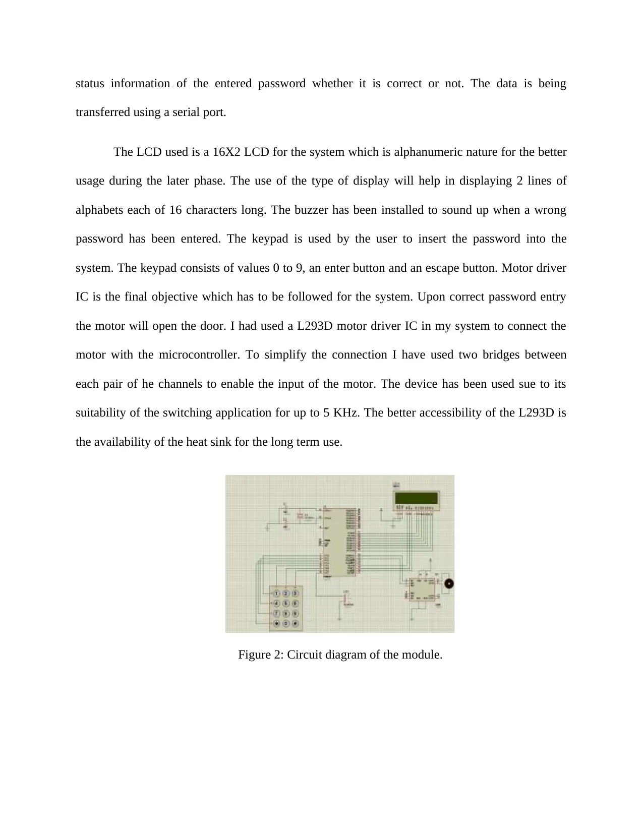
The LCD used is a 16X2 LCD for the system which is alphanumeric nature for the better
usage during the later phase. The use of the type of display will help in displaying 2 lines of
alphabets each of 16 characters long. The buzzer has been installed to sound up when a wrong
password has been entered. The keypad is used by the user to insert the password into the
system. The keypad consists of values 0 to 9, an enter button and an escape button. Motor driver
IC is the final objective which has to be followed for the system. Upon correct password entry
the motor will open the door. I had used a L293D motor driver IC in my system to connect the
motor with the microcontroller. To simplify the connection I have used two bridges between
each pair of he channels to enable the input of the motor. The device has been used sue to its
suitability of the switching application for up to 5 KHz. The better accessibility of the L293D is
the availability of the heat sink for the long term use.
Figure 2: Circuit diagram of the module.
⊘ This is a preview!⊘
Do you want full access?
Subscribe today to unlock all pages.

Trusted by 1+ million students worldwide

CE 2.3.4 Identified issues and their solutions
The issues which I had found during the implementation of the project was the problem
of storing the pins in the system. I found out that the data was not getting stored in the
microcontroller. This prompted me to change the working microcontroller to have a better
connectivity with the main system module. This enabled me to save the pins in the system for
some of the employees. Later on I found out that there were limited amount of storage available
for storing of the user id and the respective pins in the system. This forced me to change the
previous model of the microcontroller with an advanced version. This would be beneficial when
separate pin is to be stored against separate users which would make logging into the system and
unique process. The final microcontroller helped me to have a better connectivity with the
module and also have more space to store the pins with respect to the user id.
CE 2.3.5 Plan to produce creative and innovative work
For a better user interface implementation I had installed a buzzer and a logging system
in the project to log a time and date of the logging being done. For the future scope I have
thought of implementing a fingerprint locking door which will be able to provide better security
for the office or homes. I have also thought to implement a fire and LPG sensor which will open
the doors automatically for the insiders to leave fast. I would also implement the attendance
counter in the locking system which would help in keeping the track of time of the employees
coming in and going out. The data will also be transferred to a remote data base which can be
later accessed to analyse the data.
Paraphrase This Document
Need a fresh take? Get an instant paraphrase of this document with our AI Paraphraser

CE 2.3.6 Collaborative work
I had collaborated with my project supervisor to understand the working of the correct
form of microcontroller to use for the implementation of this project. I wanted to make the
project as secure as possible and also cheap for the use at homes and offices.
CE 2.4 Project Review
CE 2.4.1 Project Overview
The completion of the project suggested that the implementation of a keypad can be done
correctly to implement security protocol. The system can be used to access secured places like
residential homes, offices and industries. The implementation of a password based
implementation can be easily used to perform variable tasks. The system can used to perform the
comparison with a specific password which would be able to recognize a specific person.
CE 2.4.2 My contribution to work
I had the full contribution for this project to learn the implementations of the use of
microcontrollers and the granting of access to the authorized people. I wanted to make the
project as secure as possible and also cheap for the use at homes and offices. I had then
documented the procedure of working of the project and made the final documentation
consisting of the calculations and the diagrams which I had used during the implementation of
the project.
1 out of 8
Related Documents
Your All-in-One AI-Powered Toolkit for Academic Success.
+13062052269
info@desklib.com
Available 24*7 on WhatsApp / Email
![[object Object]](/_next/static/media/star-bottom.7253800d.svg)
Unlock your academic potential
Copyright © 2020–2026 A2Z Services. All Rights Reserved. Developed and managed by ZUCOL.


