Industrial Experience Report: Design and Fabrication of a PC3 Cabinet

Verified

Added on  2020/04/21

|41
|5731
|45
Report
AI Summary
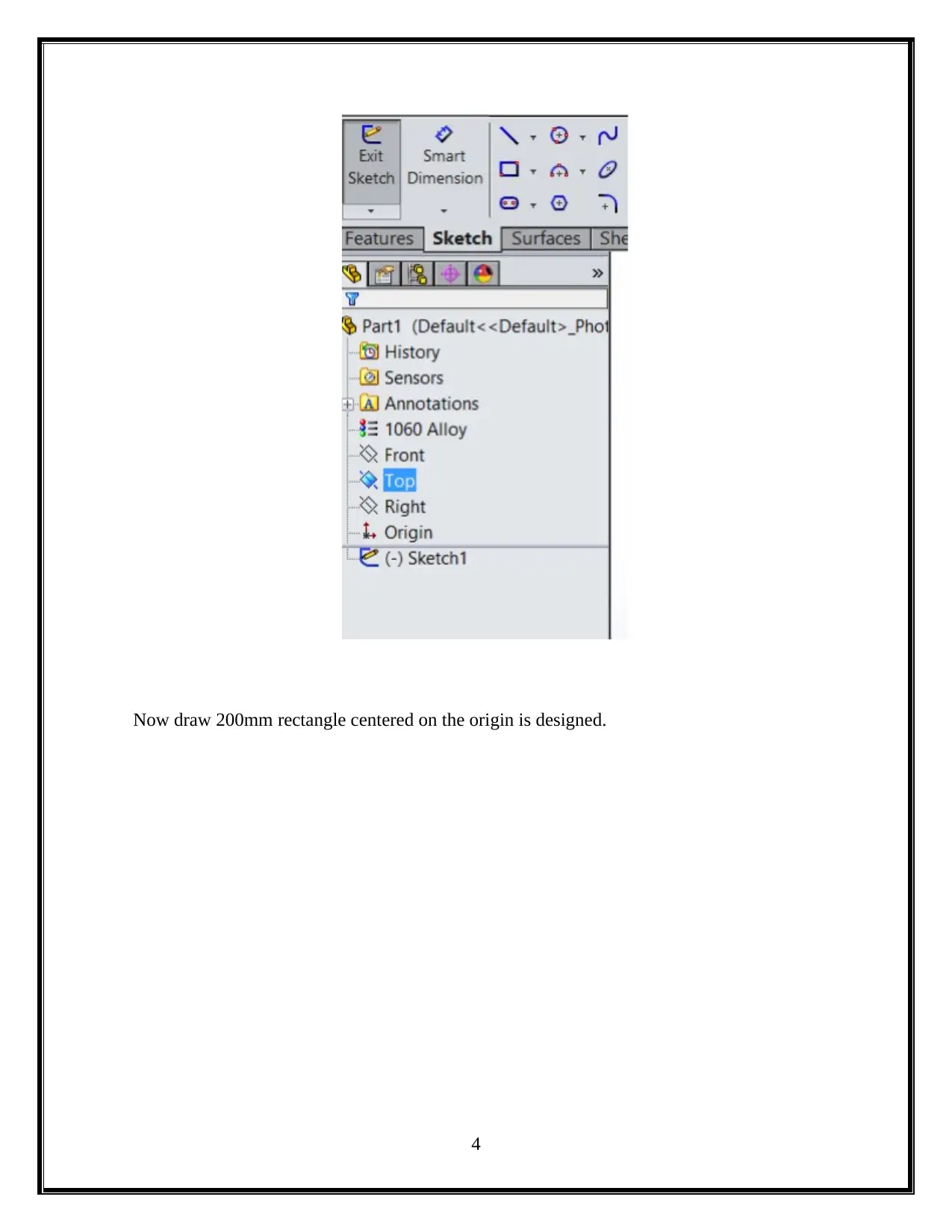
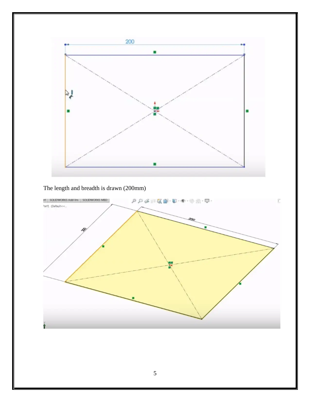
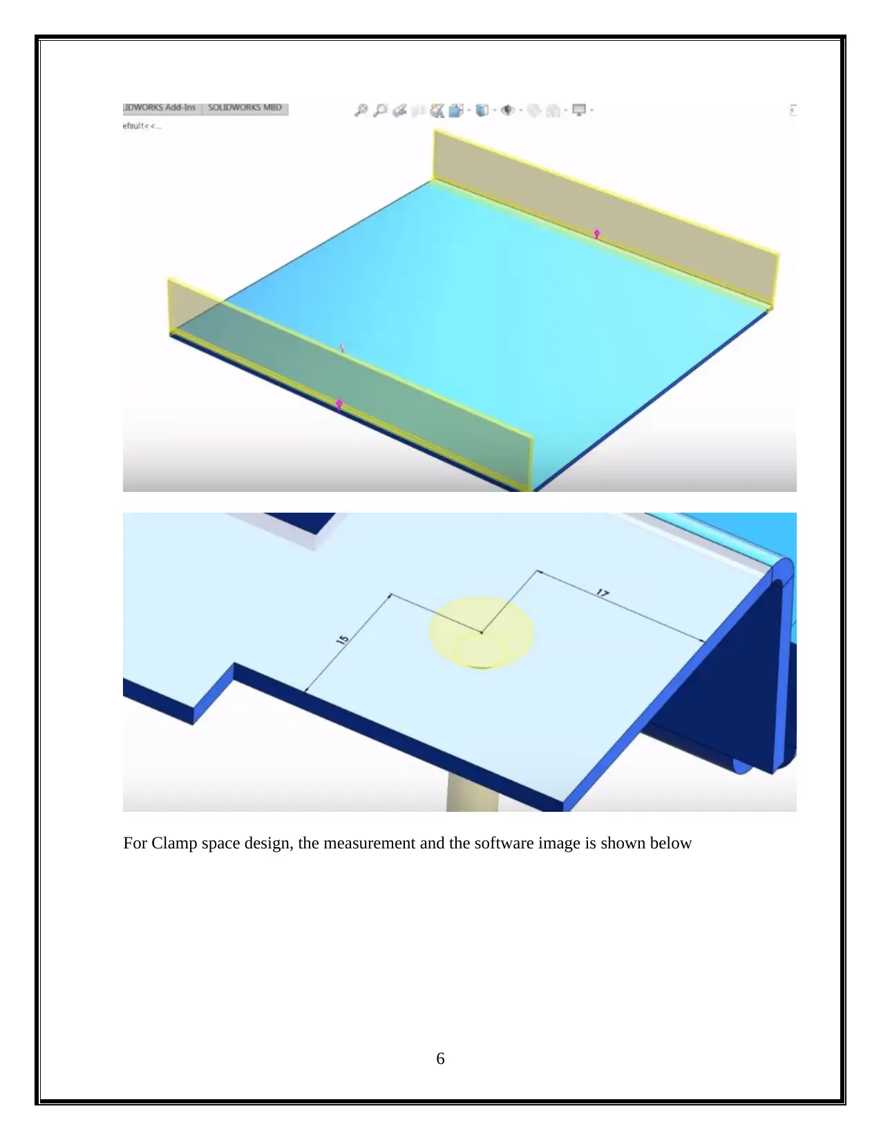
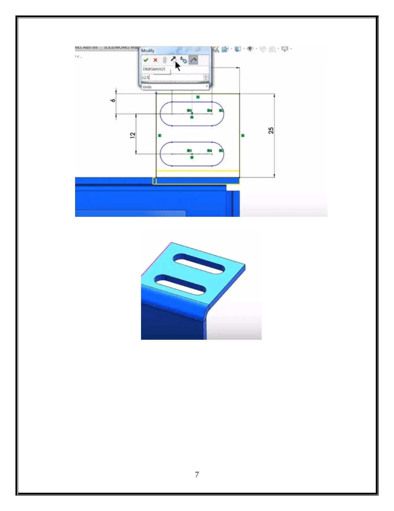
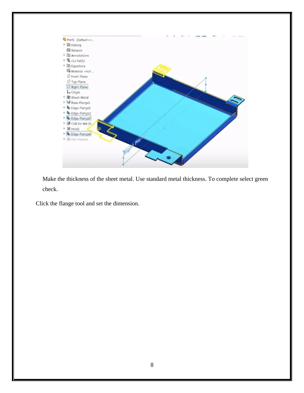
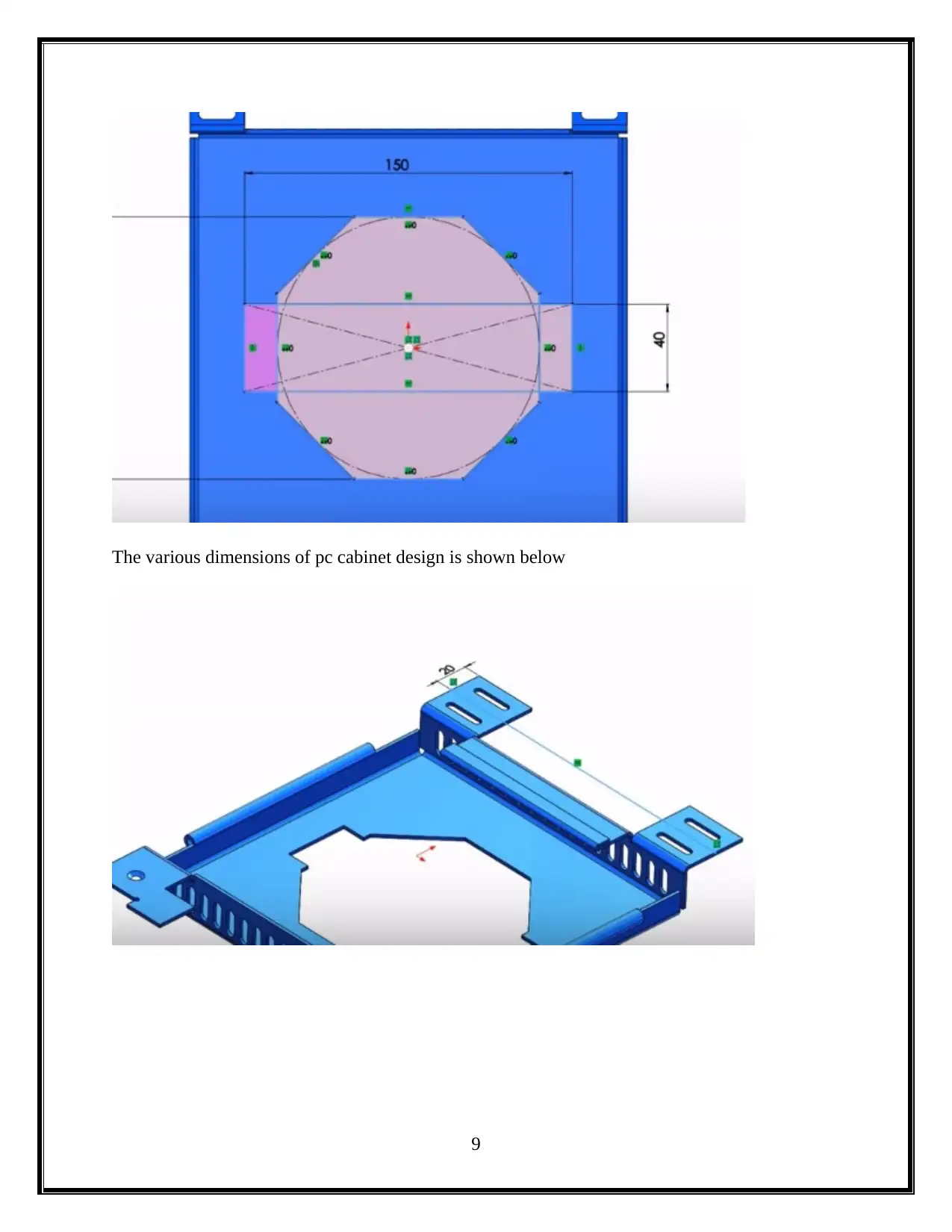
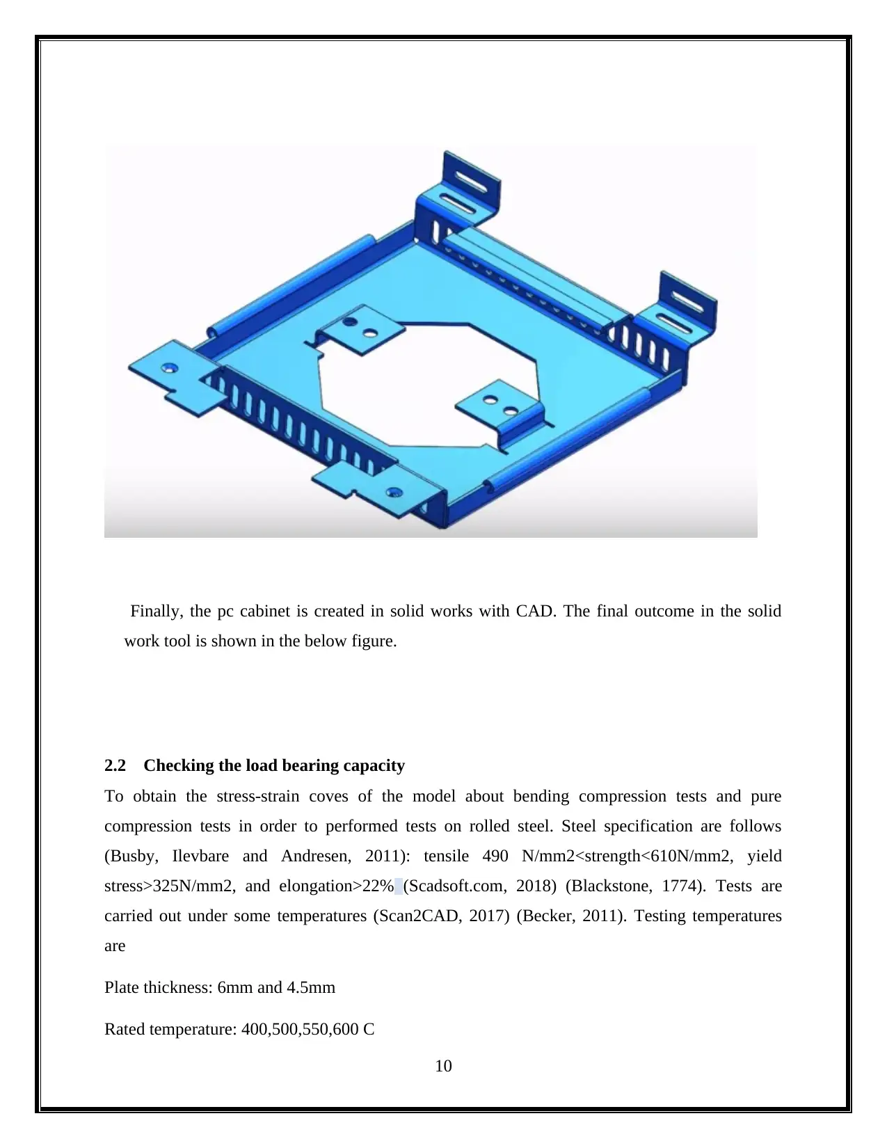
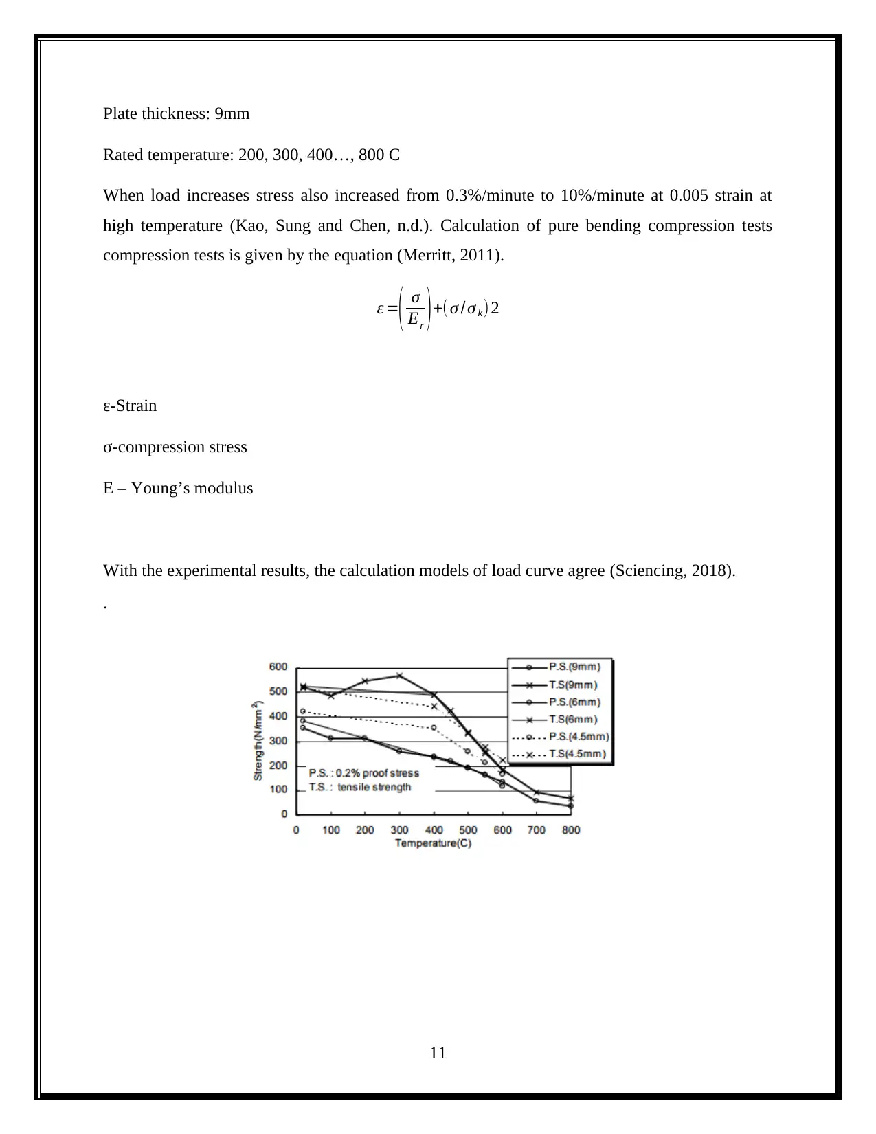
This industrial experience report documents the design and fabrication of a PC3 cabinet using SolidWorks. The report begins with an introduction to SolidWorks and its application in mechanical design, followed by a detailed description of the design process, including the creation of a 200mm rectangle and the application of sheet metal features. The report also covers the process of checking the load-bearing capacity of the cabinet, including calculations and test results. Furthermore, the report describes the construction phase, including sheet metal bending, welding, and furnishing. The report concludes with the final product and a discussion of the findings. The report also addresses research questions related to process optimization, new product development, and cost reduction. The report provides a comprehensive overview of the design and manufacturing process of a PC3 cabinet using SolidWorks, sheet metal, and welding techniques.
Document Page
industrial experience report
tabler-icon-diamond-filled.svg

Paraphrase This Document

Need a fresh take? Get an instant paraphrase of this document with our AI Paraphraser
Document Page
Table of Contents
1. Introduction.........................................................................................................................2
2. Solid works..........................................................................................................................3
2.1 Design...............................................................................................................................3
2.2 Checking the load bearing capacity............................................................................11
3. Construction......................................................................................................................14
3.1 Sheet Metal bending......................................................................................................15
3.2 Welding..........................................................................................................................17
3.3 Furnishing......................................................................................................................22
4. Final product.....................................................................................................................24
5. Conclusion.........................................................................................................................25
References.................................................................................................................................26
1
Document Page
1. Introduction
CPR group of company took the first step in the process of Optimization. Solid works is a 3D
CAD software that is used in designing the automation application in mechanical design. It
allows the designers to quickly draw the experiments with dimensions and features and sketch
the ideas. The designing process is coved by the SolidWorks from design to technical
communication. Solid works also include the data management in the designing process. The
productivity of our design can be increased by the SolidWorks. It is an integrated software with
intuitive design. A better cost-effective products can be delivered by this software. This 3D CAD
software allows the user to draw a solid form. It is a solid modeler and it make use of parametric
approach to create 3D solid models. In this report, design and fabrication is made for pc3 cabinet
by using a stainless steel metal. The pc3 cabinet is designed with the specified shape and
dimensions. With the space provided, the load-bearing capacity of the pc3 cabinet will be
checked.
Here, the following research questions will be answered
How can the building painting process works more efficiently using new technologies?
How can the current process enhance and works better in time management/process
optimization?
How can the current process works better in optimize a new product?
How can the environmental stress reduce the usage of new technologies?
How much the cost gets low with the new product?
The problem with this solution is to set a new product that can use for the painting process. This
can't help in innovating at CPR group of the company but it will have a new innovative product
in paint equipment trending in the market.
2. Solid works
All aspects of development product process with a seamless, sustainable design, communication,
and integrated workflow-design. The integrated software work and intuitive design interface
work together and give the focus on innovation. In solid works, building the model usually starts
with a 2D sketch (3D sketches also available). Points, arcs, lines, conics, and splines are
2
Document Page
available in the sketch. The drawings can be created either for assemblies or for other parts.
Views of the solid model are automatically generated (Budkin and Erofeev, 2011).
2.1 Design
To design the pc cabinet in the solid works, start a new part using inches and make enable the
sheet metal ribbon. Check next to sheet metal and right click on the ribbon. Then make the
material to 1060 alloy by right click material on browser then select 1060 alloy in the list
(Weisel, 2004).
On the top plane, a new sketch is been started
3
tabler-icon-diamond-filled.svg

Paraphrase This Document

Need a fresh take? Get an instant paraphrase of this document with our AI Paraphraser
Document Page
Now draw 200mm rectangle centered on the origin is designed.
4
Document Page
The length and breadth is drawn (200mm)
5
Document Page
For Clamp space design, the measurement and the software image is shown below
6
tabler-icon-diamond-filled.svg

Paraphrase This Document

Need a fresh take? Get an instant paraphrase of this document with our AI Paraphraser
Document Page
7
Document Page
Make the thickness of the sheet metal. Use standard metal thickness. To complete select green
check.
Click the flange tool and set the dimension.
8
Document Page
The various dimensions of pc cabinet design is shown below
9
tabler-icon-diamond-filled.svg

Paraphrase This Document

Need a fresh take? Get an instant paraphrase of this document with our AI Paraphraser
Document Page
Finally, the pc cabinet is created in solid works with CAD. The final outcome in the solid
work tool is shown in the below figure.
2.2 Checking the load bearing capacity
To obtain the stress-strain coves of the model about bending compression tests and pure
compression tests in order to performed tests on rolled steel. Steel specification are follows
(Busby, Ilevbare and Andresen, 2011): tensile 490 N/mm2<strength<610N/mm2, yield
stress>325N/mm2, and elongation>22% (Scadsoft.com, 2018) (Blackstone, 1774). Tests are
carried out under some temperatures (Scan2CAD, 2017) (Becker, 2011). Testing temperatures
are
Plate thickness: 6mm and 4.5mm
Rated temperature: 400,500,550,600 C
10
Document Page
Plate thickness: 9mm
Rated temperature: 200, 300, 400…, 800 C
When load increases stress also increased from 0.3%/minute to 10%/minute at 0.005 strain at
high temperature (Kao, Sung and Chen, n.d.). Calculation of pure bending compression tests
compression tests is given by the equation (Merritt, 2011).
ε =
( σ
Er )+( σ /σ k) 2
ε-Strain
σ-compression stress
E – Young’s modulus
With the experimental results, the calculation models of load curve agree (Sciencing, 2018).
.
11
chevron_up_icon
1 out of 41
circle_padding
hide_on_mobile
zoom_out_icon
[object Object]