Comparative Study on Multichannel and U-Shaped PCB Assembly Layout
VerifiedAdded on 2023/01/12
|27
|9399
|30
Report
AI Summary
This report presents a comparative study on multichannel and U-shaped assembly layouts for PCB (Printed Circuit Board) assembly lines, utilizing Flexsim simulation software for educational purposes. The study delves into the literature review of PCB assembly, including the steps involved in the simulation process for both Insertion Mount Technology (IMT) and Surface Mount Technology (SMT). The report explains the application of Flexsim for modeling and simulating assembly lines, emphasizing the software's capabilities in creating 3D-based models for various manufacturing processes. It highlights the significance of simulation in the design and optimization of PCB assembly lines, including cost and time analysis. Furthermore, the report explores the use of simulation for educational purposes, emphasizing the benefits of simulated learning activities in engineering and related fields. It also discusses the historical use of simulation in training, highlighting examples from aviation and healthcare, and explores the integration of computer-based games in training and education. The report aims to provide a comprehensive understanding of PCB assembly processes and how simulation can be leveraged to improve design efficiency and overall system performance.

Dissertation
1
1
Paraphrase This Document
Need a fresh take? Get an instant paraphrase of this document with our AI Paraphraser
Table of Contents
Topic: Comparative Study on Multichannel and U-Shaped Assembly Layout of PCB Assembly
using Flexism Simulation for Educational Purpose.........................................................................3
Literature Review.............................................................................................................................3
Introduction..................................................................................................................................3
Steps for simulation.....................................................................................................................3
.....................................................................................................................................................5
Simulation for educational purpose.............................................................................................9
Performing cost analysis for assembly lines..............................................................................13
Performing time analysis for assembly lines.............................................................................16
Significance in simulation of PCB assembly lines....................................................................18
Significance of finding efficiency of assemble line layout.......................................................22
Conclusion.....................................................................................................................................25
REFERENCES..............................................................................................................................26
2
Topic: Comparative Study on Multichannel and U-Shaped Assembly Layout
of PCB Assembly using Flexism Simulation for Educational Purpose
Literature Review
Introduction
Printed circuit boards or PCBs are unsung heroes present in modern electronic devices,
which are designed to help new as well as seasoned engineers, to make better informed decisions
in fewer periods, to end up with appropriate and perfect components for product development.
As fundamental characteristic, of competitive environment in today’s world includes the
requirement of shorter product life cycles as well as increased demands for the customization (Jo
and Kim, 2018). But as these aspects seems to be difficult for satisfying operating via traditional
production lines. Therefore, JIT U-lines development is being the emerging response for
competing in such competing environment. The present literature review describes the
simulation utilization to guide the efforts for improvement while redesigning the PCB assembly.
A comparative study is done on U-shaped and multichannel layout of this assembly, by using
flexism simulation in educational purpose. The study is done to understand the PCB assembly
process by using simulation with flexism approach. To improve the overall performance of
system, feasibility of flow logic process is assessed, including impact of changing line
configuration.
Steps for simulation
Simulation of the electronic circuit mostly uses a number of mathematical models for
getting the actual behaviour of electronic devices like PCB (Printed circuit board). Simulation
software helps in modelling the electronic circuit operation. Through research, it has been
evaluated that before manufacturing, simulating the circuit behaviour helps in improving and
increasing the design efficiency. PCB designing which requires modelling like IBIS models,
transmission lines etc. so, simulator includes schematic editor, waveform display, simulation
engine and more, that monitors the effect also which may occur during operation. PCB or printed
circuit board assembly lines are mainly fall within serial production line general category. But
common problem that might be faced by engineers during designing configuration of future or
existing lines for meeting targeted production rates. Therefore, simulation modelling helps in
capturing the complex behaviour as well as interaction among various components of assembly
3
⊘ This is a preview!⊘
Do you want full access?
Subscribe today to unlock all pages.
Trusted by 1+ million students worldwide
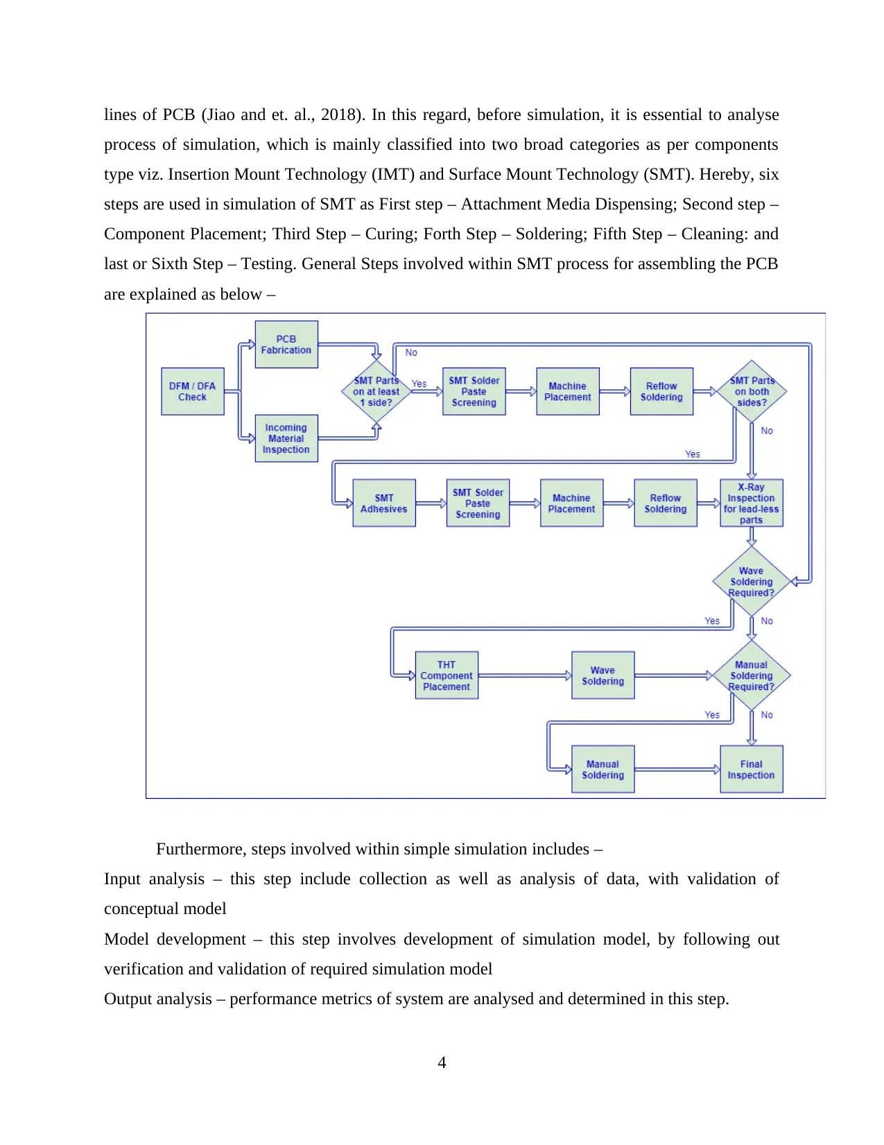
lines of PCB (Jiao and et. al., 2018). In this regard, before simulation, it is essential to analyse
process of simulation, which is mainly classified into two broad categories as per components
type viz. Insertion Mount Technology (IMT) and Surface Mount Technology (SMT). Hereby, six
steps are used in simulation of SMT as First step – Attachment Media Dispensing; Second step –
Component Placement; Third Step – Curing; Forth Step – Soldering; Fifth Step – Cleaning: and
last or Sixth Step – Testing. General Steps involved within SMT process for assembling the PCB
are explained as below –
Furthermore, steps involved within simple simulation includes –
Input analysis – this step include collection as well as analysis of data, with validation of
conceptual model
Model development – this step involves development of simulation model, by following out
verification and validation of required simulation model
Output analysis – performance metrics of system are analysed and determined in this step.
4
Paraphrase This Document
Need a fresh take? Get an instant paraphrase of this document with our AI Paraphraser
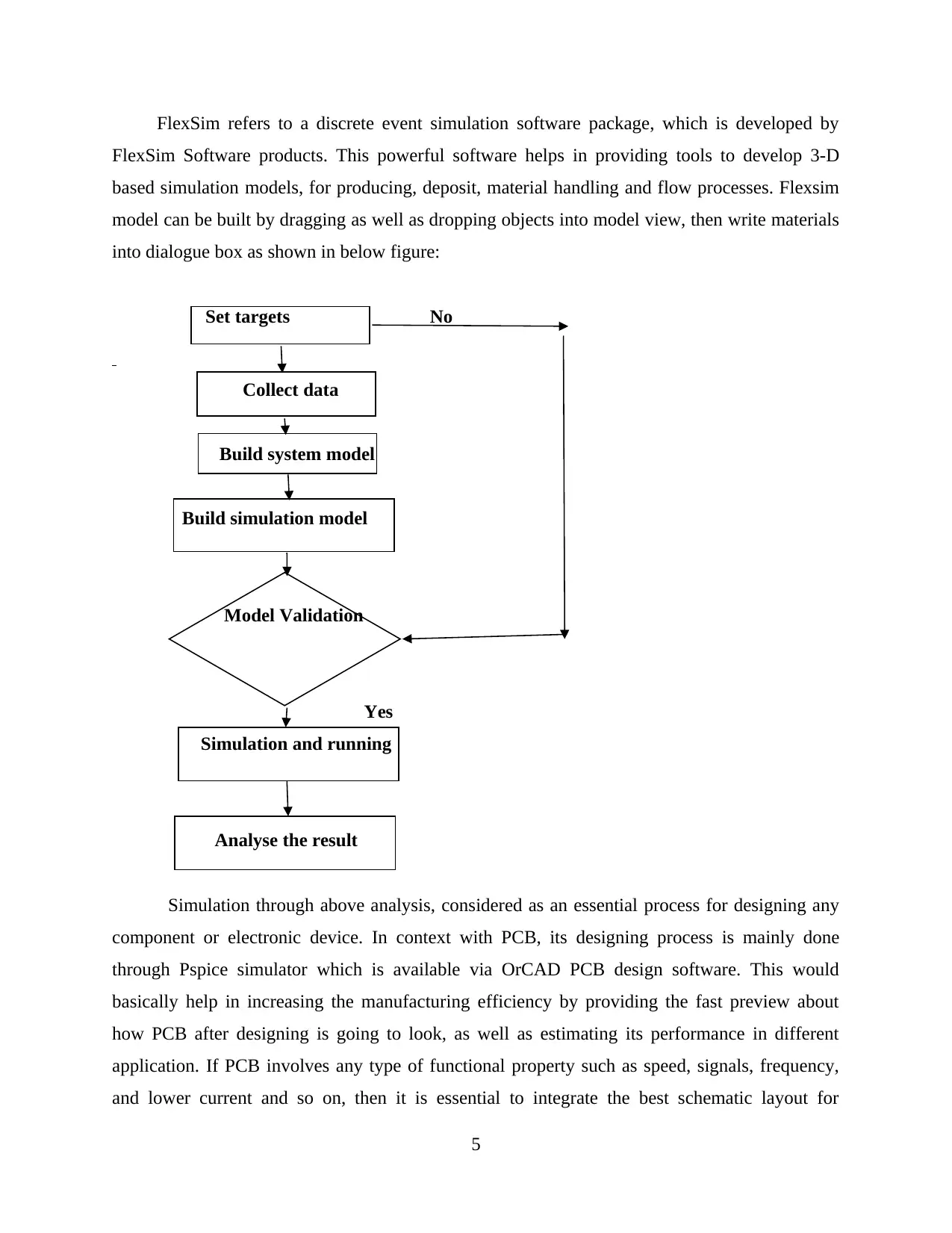
FlexSim refers to a discrete event simulation software package, which is developed by
FlexSim Software products. This powerful software helps in providing tools to develop 3-D
based simulation models, for producing, deposit, material handling and flow processes. Flexsim
model can be built by dragging as well as dropping objects into model view, then write materials
into dialogue box as shown in below figure:
Set targets No
Collect data
Build system model
Build simulation model
Model Validation
Yes
Simulation and running
Analyse the result
Simulation through above analysis, considered as an essential process for designing any
component or electronic device. In context with PCB, its designing process is mainly done
through Pspice simulator which is available via OrCAD PCB design software. This would
basically help in increasing the manufacturing efficiency by providing the fast preview about
how PCB after designing is going to look, as well as estimating its performance in different
application. If PCB involves any type of functional property such as speed, signals, frequency,
and lower current and so on, then it is essential to integrate the best schematic layout for
5
integrating the system with specific simulation tools. Therefore, by simulating the PCB,
parameters like signal integrity, power delivery, mixed signal simulation and others, can easily
be analysed. Thus, for creating simulation in PCB assembly, it is required to create the
simulation profile first, under which process like selection of analysis type can be done, that can
be refused also when required. Hereby, through creation of simulation profile, editing and
modifications also can be done as per PCB design. Therefore, following steps can be used for
creating simulation profile –
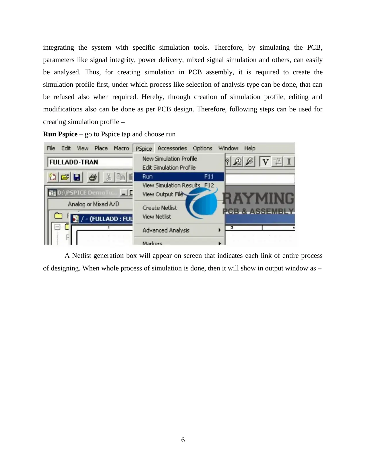
Run Pspice – go to Pspice tap and choose run
A Netlist generation box will appear on screen that indicates each link of entire process
of designing. When whole process of simulation is done, then it will show in output window as –
6
parameters like signal integrity, power delivery, mixed signal simulation and others, can easily
be analysed. Thus, for creating simulation in PCB assembly, it is required to create the
simulation profile first, under which process like selection of analysis type can be done, that can
be refused also when required. Hereby, through creation of simulation profile, editing and
modifications also can be done as per PCB design. Therefore, following steps can be used for
creating simulation profile –
Run Pspice – go to Pspice tap and choose run
A Netlist generation box will appear on screen that indicates each link of entire process
of designing. When whole process of simulation is done, then it will show in output window as –
6
⊘ This is a preview!⊘
Do you want full access?
Subscribe today to unlock all pages.
Trusted by 1+ million students worldwide
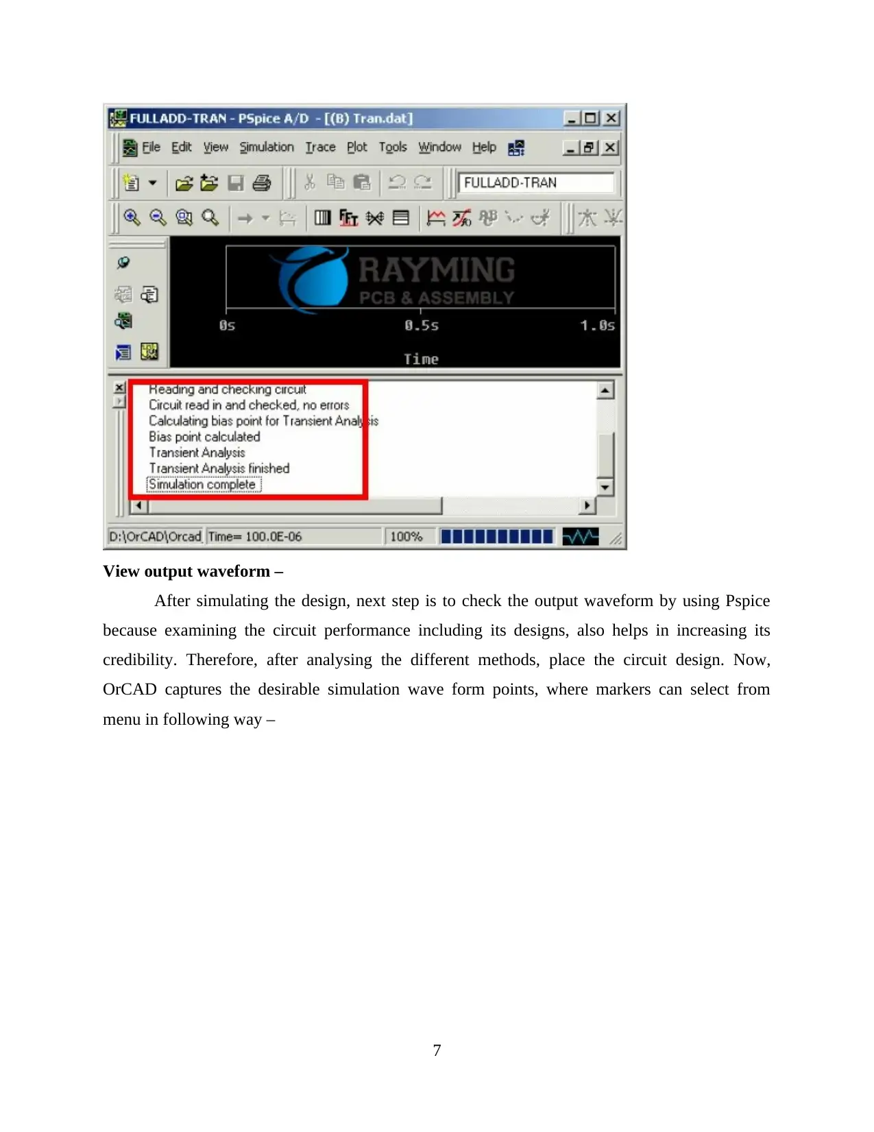
View output waveform –
After simulating the design, next step is to check the output waveform by using Pspice
because examining the circuit performance including its designs, also helps in increasing its
credibility. Therefore, after analysing the different methods, place the circuit design. Now,
OrCAD captures the desirable simulation wave form points, where markers can select from
menu in following way –
7
Paraphrase This Document
Need a fresh take? Get an instant paraphrase of this document with our AI Paraphraser
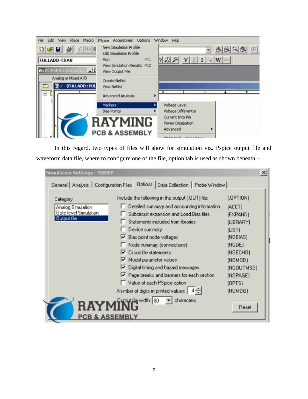
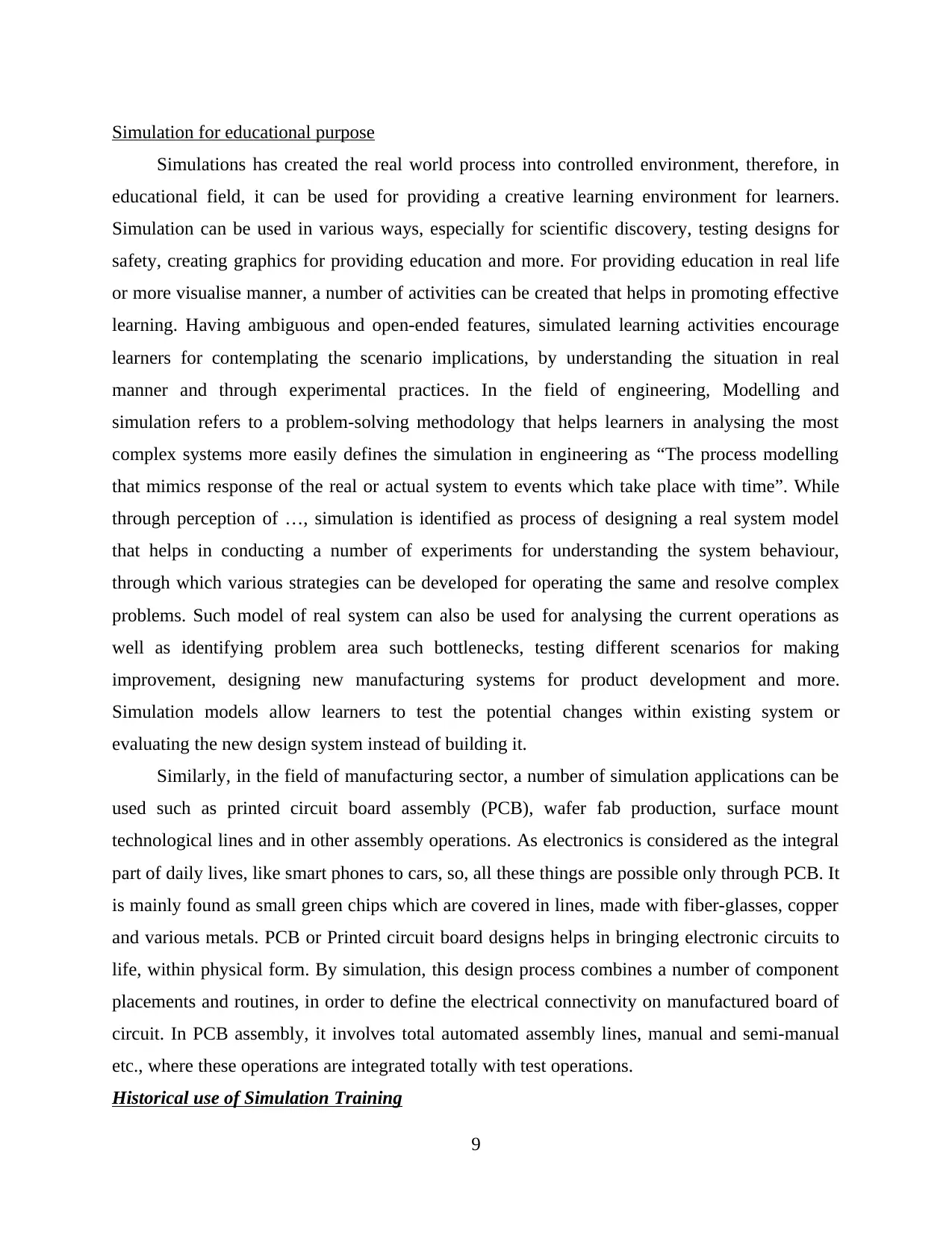
In this regard, two types of files will show for simulation viz. Pspice output file and
waveform data file, where to configure one of the file, option tab is used as shown beneath –
8
waveform data file, where to configure one of the file, option tab is used as shown beneath –
8
Simulation for educational purpose
Simulations has created the real world process into controlled environment, therefore, in
educational field, it can be used for providing a creative learning environment for learners.
Simulation can be used in various ways, especially for scientific discovery, testing designs for
safety, creating graphics for providing education and more. For providing education in real life
or more visualise manner, a number of activities can be created that helps in promoting effective
learning. Having ambiguous and open-ended features, simulated learning activities encourage
learners for contemplating the scenario implications, by understanding the situation in real
manner and through experimental practices. In the field of engineering, Modelling and
simulation refers to a problem-solving methodology that helps learners in analysing the most
complex systems more easily defines the simulation in engineering as “The process modelling
that mimics response of the real or actual system to events which take place with time”. While
through perception of …, simulation is identified as process of designing a real system model
that helps in conducting a number of experiments for understanding the system behaviour,
through which various strategies can be developed for operating the same and resolve complex
problems. Such model of real system can also be used for analysing the current operations as
well as identifying problem area such bottlenecks, testing different scenarios for making
improvement, designing new manufacturing systems for product development and more.
Simulation models allow learners to test the potential changes within existing system or
evaluating the new design system instead of building it.
Similarly, in the field of manufacturing sector, a number of simulation applications can be
used such as printed circuit board assembly (PCB), wafer fab production, surface mount
technological lines and in other assembly operations. As electronics is considered as the integral
part of daily lives, like smart phones to cars, so, all these things are possible only through PCB. It
is mainly found as small green chips which are covered in lines, made with fiber-glasses, copper
and various metals. PCB or Printed circuit board designs helps in bringing electronic circuits to
life, within physical form. By simulation, this design process combines a number of component
placements and routines, in order to define the electrical connectivity on manufactured board of
circuit. In PCB assembly, it involves total automated assembly lines, manual and semi-manual
etc., where these operations are integrated totally with test operations.
Historical use of Simulation Training
9
⊘ This is a preview!⊘
Do you want full access?
Subscribe today to unlock all pages.
Trusted by 1+ million students worldwide
The use of simulation throughout training and education brings a lot to
continuing learning in aviation that has more than half a century of knowledge and "learned the
lessons" with computer simulations and visualization. Aviation simulators had already also been
enough to educate working memory given task or multiple tasks, but also activities in the
cognitive aspects over the past couple of decades. Affective-domain preparation was directed at
enhancing employee efficiency and reducing injuries causing mechanical failure. Aviation
outcomes were in virtually eliminating air carrier accidental deaths. For instance, Kohn,
Corrigan, and Donaldson (2000) uphold the gains that aircraft education has achieved since the
Second World War as a framework for many other sectors and several businesses are now
designing more complex training simulators so that staff in areas such as health can get leverage
from simulation learning.
Medical Simulation Training
The healthcare industry is among the largest growing modelling and simulation regions but
has previously been seeing a development in the use of simulation studies and simulation games
for professional development. Such simulators usually have functionalities with the operating
systems that can provide coaching throughout the cognitive function abilities needed for
particular medical interventions. For example, Immersion Medical manufactures an ultrasound
simulator which enables instructors to perform different categories of endoscopic procedures in
an environment is also healthy for the patient, as a simulation patient is being used, and presents
the trainee with input on the activity. As per Lian and Chen (2006), medical study employed not
only strong ecological simulation performance and furthermore haptic simulation. They further
note that "a basic and common application of skilled design, virtual catheter insertion solves
challenging issues like soft tissue simulation, path planning, and force modelling." Their
software uses advanced mathematical algorithms to map characteristic properties for a much
more realistic virtual reality (VR) of body cells and a much more realistic haptic representation
of the person-VR interfaces. It included a logical knowledge set, problem solving and decision-
making capabilities, effective psychosocial interactions, as well as other qualities which can be
evaluated through quantitative tests, such as advisory committee or specialist qualification
examinations. Maybe most important to the physician, though, is the profession’s key
professional skills. A battery of advanced tools is being developed to educate and provide good
arguable of the technological capability of the trainee. In healthcare sectors, the selection of
10
Paraphrase This Document
Need a fresh take? Get an instant paraphrase of this document with our AI Paraphraser
simulators may vary from basic part-task instructors equipped to teach a single assignment to
more complex computer simulations that can perform several activities, just as in aviation. These
ground breaking state-of-the-art modelling tools may be very effective in guiding and testing the
cognitive and psychomotor abilities of student nurses; nevertheless, they can be quickly
misrepresented, over- or under-used, and significantly push up cost of training through sufficient
instruction or practice.
Computer-based Games in Training and Education
Computer-based gaming with basic "score" or human-computer interaction (e.g., games,
geometry wars, etc.) started as mere entertainment. Computer-based gaming’s have evolved at a
very rapid pace from such a time, a trend which has closely exemplified the growth of more
efficient personal computers. Computer-based players are becoming very advanced, as well as a
huge portion of the entertainment market, as demonstrated by products like Halo 3. Such new
state-of-the-art interactive games have used a range of technologies such as: multi-player
asynchronous playing games, haptic feedback, virtual reality and strong visual and audio quality.
Through the advent of computer-based educational games, they started to be integrated as a tool
of training and education to accomplish specific learning goals. Gopher et al., (2014) find the
flight success results for two cadet teams, which got ten hours In following test flights the
preparation was significantly better than someone with no experience of playing. As per Ruben
(2009), computer-based games will provide the ability to learn and exercise expertise or abilities
and obtain an understanding of the fundamental conceptual structures of the perceptions of the
students. ActivChemistry as seen in Figure is an example of a chemistry laboratory’s educational
simulations. This is a mechanical building kit that offers materials and equipment for learners,
like fluorescent lamps, materials, as well as a wide range of measurements and pressure sensors.
Through immersive and creative lessons, students use these elements to conduct experiments,
collect and data types, and experiment with new concepts. Based on the actual devices,
ActivChemistry shows many benefits of using simulation. Such benefits include protection
experiments that are just too risky for most school chemistry laboratories.
11
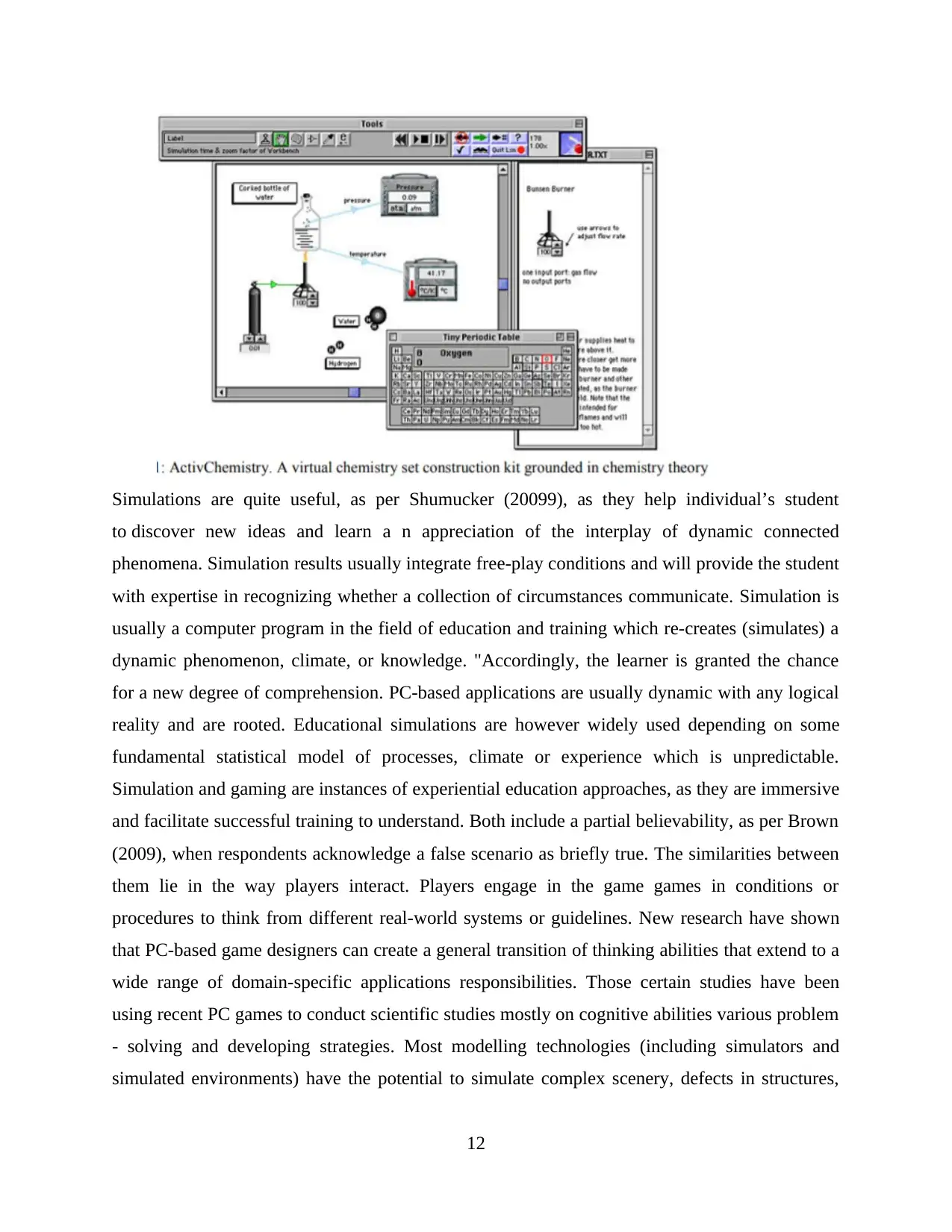
Simulations are quite useful, as per Shumucker (20099), as they help individual’s student
to discover new ideas and learn a n appreciation of the interplay of dynamic connected
phenomena. Simulation results usually integrate free-play conditions and will provide the student
with expertise in recognizing whether a collection of circumstances communicate. Simulation is
usually a computer program in the field of education and training which re-creates (simulates) a
dynamic phenomenon, climate, or knowledge. "Accordingly, the learner is granted the chance
for a new degree of comprehension. PC-based applications are usually dynamic with any logical
reality and are rooted. Educational simulations are however widely used depending on some
fundamental statistical model of processes, climate or experience which is unpredictable.
Simulation and gaming are instances of experiential education approaches, as they are immersive
and facilitate successful training to understand. Both include a partial believability, as per Brown
(2009), when respondents acknowledge a false scenario as briefly true. The similarities between
them lie in the way players interact. Players engage in the game games in conditions or
procedures to think from different real-world systems or guidelines. New research have shown
that PC-based game designers can create a general transition of thinking abilities that extend to a
wide range of domain-specific applications responsibilities. Those certain studies have been
using recent PC games to conduct scientific studies mostly on cognitive abilities various problem
- solving and developing strategies. Most modelling technologies (including simulators and
simulated environments) have the potential to simulate complex scenery, defects in structures,
12
⊘ This is a preview!⊘
Do you want full access?
Subscribe today to unlock all pages.
Trusted by 1+ million students worldwide
1 out of 27

Your All-in-One AI-Powered Toolkit for Academic Success.
+13062052269
info@desklib.com
Available 24*7 on WhatsApp / Email
![[object Object]](/_next/static/media/star-bottom.7253800d.svg)
Unlock your academic potential
Copyright © 2020–2026 A2Z Services. All Rights Reserved. Developed and managed by ZUCOL.