Evaluating and Comparing PCB Test Jig Design Solutions in Engineering

Verified

Added on  2020/11/23

|7
|1001
|255
Report
AI Summary
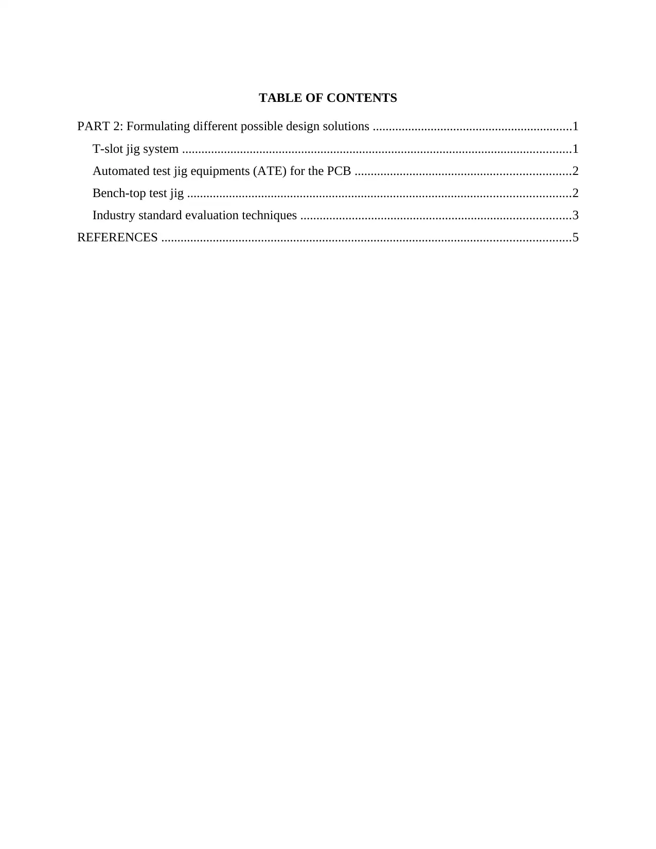
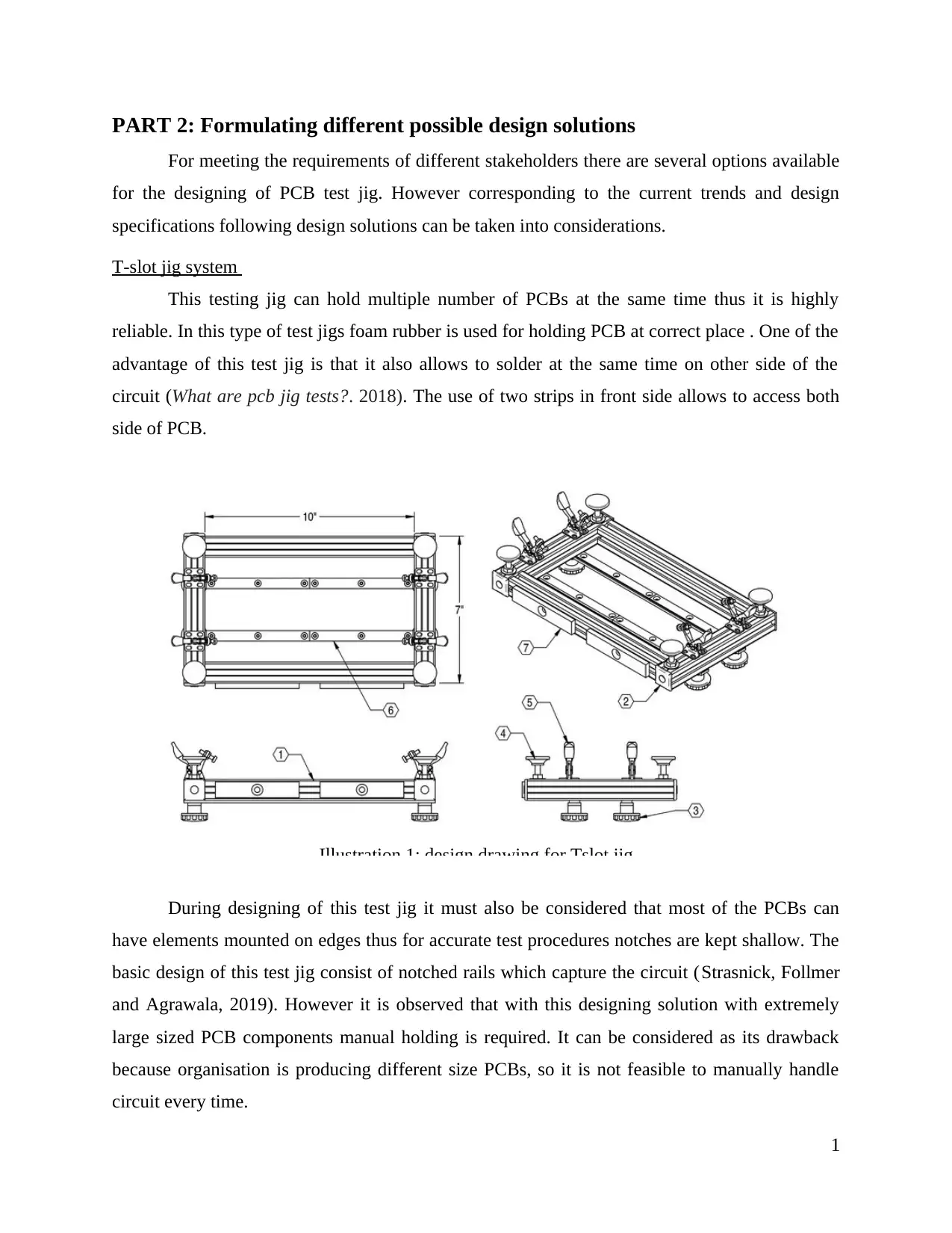
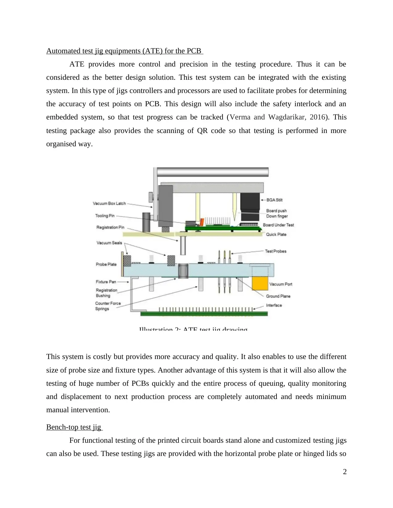
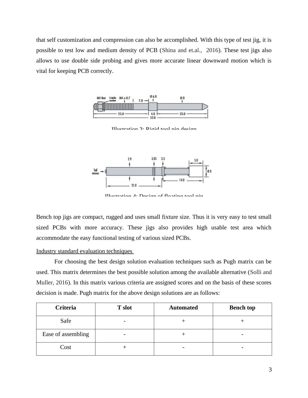
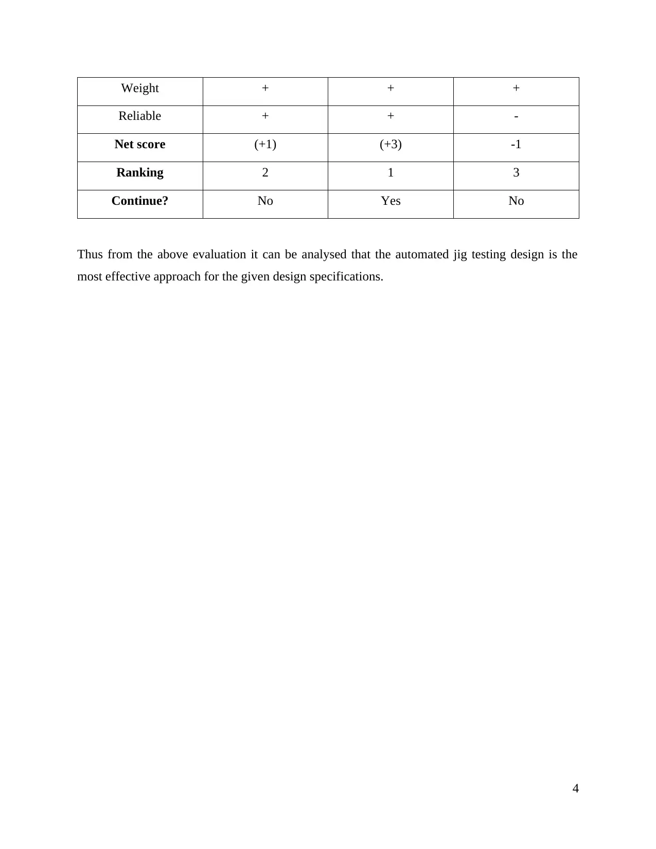
This report presents an analysis of different design solutions for PCB test jigs, crucial for ensuring the quality and functionality of printed circuit boards. It explores three primary design options: the T-slot jig system, automated test jig equipments (ATE), and bench-top test jigs. The T-slot jig is highlighted for its ability to hold multiple PCBs simultaneously, while ATE offers greater control and precision through the use of controllers and processors, including safety interlocks and QR code scanning. Bench-top jigs are presented as compact, rugged solutions for testing low and medium-density PCBs. The report employs industry-standard evaluation techniques, specifically the Pugh matrix, to compare the different design solutions based on criteria such as safety, ease of assembly, cost, weight, and reliability, ultimately concluding that the automated jig testing design is the most effective approach for the given design specifications. The report also includes relevant references to support the analysis.
Document Page
Engineering Design
tabler-icon-diamond-filled.svg

Paraphrase This Document

Need a fresh take? Get an instant paraphrase of this document with our AI Paraphraser
Document Page
TABLE OF CONTENTS
PART 2: Formulating different possible design solutions ..............................................................1
T-slot jig system .........................................................................................................................1
Automated test jig equipments (ATE) for the PCB ...................................................................2
Bench-top test jig .......................................................................................................................2
Industry standard evaluation techniques ....................................................................................3
REFERENCES ...............................................................................................................................5
Document Page
PART 2: Formulating different possible design solutions
For meeting the requirements of different stakeholders there are several options available
for the designing of PCB test jig. However corresponding to the current trends and design
specifications following design solutions can be taken into considerations.
T-slot jig system
This testing jig can hold multiple number of PCBs at the same time thus it is highly
reliable. In this type of test jigs foam rubber is used for holding PCB at correct place . One of the
advantage of this test jig is that it also allows to solder at the same time on other side of the
circuit (What are pcb jig tests?. 2018). The use of two strips in front side allows to access both
side of PCB.
During designing of this test jig it must also be considered that most of the PCBs can
have elements mounted on edges thus for accurate test procedures notches are kept shallow. The
basic design of this test jig consist of notched rails which capture the circuit (Strasnick, Follmer
and Agrawala, 2019). However it is observed that with this designing solution with extremely
large sized PCB components manual holding is required. It can be considered as its drawback
because organisation is producing different size PCBs, so it is not feasible to manually handle
circuit every time.
1
Illustration 1: design drawing for Tslot jig
Document Page
Automated test jig equipments (ATE) for the PCB
ATE provides more control and precision in the testing procedure. Thus it can be
considered as the better design solution. This test system can be integrated with the existing
system. In this type of jigs controllers and processors are used to facilitate probes for determining
the accuracy of test points on PCB. This design will also include the safety interlock and an
embedded system, so that test progress can be tracked (Verma and Wagdarikar, 2016). This
testing package also provides the scanning of QR code so that testing is performed in more
organised way.
This system is costly but provides more accuracy and quality. It also enables to use the different
size of probe size and fixture types. Another advantage of this system is that it will also allow the
testing of huge number of PCBs quickly and the entire process of queuing, quality monitoring
and displacement to next production process are completely automated and needs minimum
manual intervention.
Bench-top test jig
For functional testing of the printed circuit boards stand alone and customized testing jigs
can also be used. These testing jigs are provided with the horizontal probe plate or hinged lids so
2
Illustration 2: ATE test jig drawing
tabler-icon-diamond-filled.svg

Paraphrase This Document

Need a fresh take? Get an instant paraphrase of this document with our AI Paraphraser
Document Page
that self customization and compression can also be accomplished. With this type of test jig, it is
possible to test low and medium density of PCB (Shina and et.al., 2016). These test jigs also
allows to use double side probing and gives more accurate linear downward motion which is
vital for keeping PCB correctly.
Bench top jigs are compact, rugged and uses small fixture size. Thus it is very easy to test small
sized PCBs with more accuracy. These jigs also provides high usable test area which
accommodate the easy functional testing of various sized PCBs.
Industry standard evaluation techniques
For choosing the best design solution evaluation techniques such as Pugh matrix can be
used. This matrix determines the best possible solution among the available alternative (Solli and
Muller, 2016). In this matrix various criteria are assigned scores and on the basis of these scores
decision is made. Pugh matrix for the above design solutions are as follows:
Criteria T slot Automated Bench top
Safe - + +
Ease of assembling - + -
Cost + - -
3
Illustration 3: Rigid tool pin design
Illustration 4: Design of floating tool pin
Document Page
Weight + + +
Reliable + + -
Net score (+1) (+3) -1
Ranking 2 1 3
Continue? No Yes No
Thus from the above evaluation it can be analysed that the automated jig testing design is the
most effective approach for the given design specifications.
4
Document Page
REFERENCES
Books and Journals
Shina, S. and et.al., 2016, January. Development of tools and techniques for mechanical
property testing and analysis of experimental nano solder. In Pan Pacific
Microelectronics Symposium (Pan Pacific), 2016 (pp. 1-11). IEEE.
Solli, H. and Muller, G., 2016, July. Evaluation of illustrative ConOps and Decision Matrix as
tools in concept selection. InINCOSE International Symposium (Vol. 26, No. 1, pp.
2361-2375).
Strasnick, E., Follmer, S. and Agrawala, M., 2019. Pinpoint: A PCB Debugging Pipeline Using
Interruptible Routing and Instrumentation.
Verma, S. and Wagdarikar, N.M., 2016, September. Automated test jig for refrigerator PCB
performance. InAutomatic Control and Dynamic Optimization Techniques (ICACDOT),
International Conference on (pp. 840-843). IEEE.
Online
What are pcb jig tests?. 2018. [Online]. Accessed through <https://meee-services.com/what-are-
pcb-jig-tests/>
5
chevron_up_icon
1 out of 7
circle_padding
hide_on_mobile
zoom_out_icon
[object Object]