Analyzing Pelton Turbine for Aircraft Engine Application: Forces
VerifiedAdded on 2023/05/29
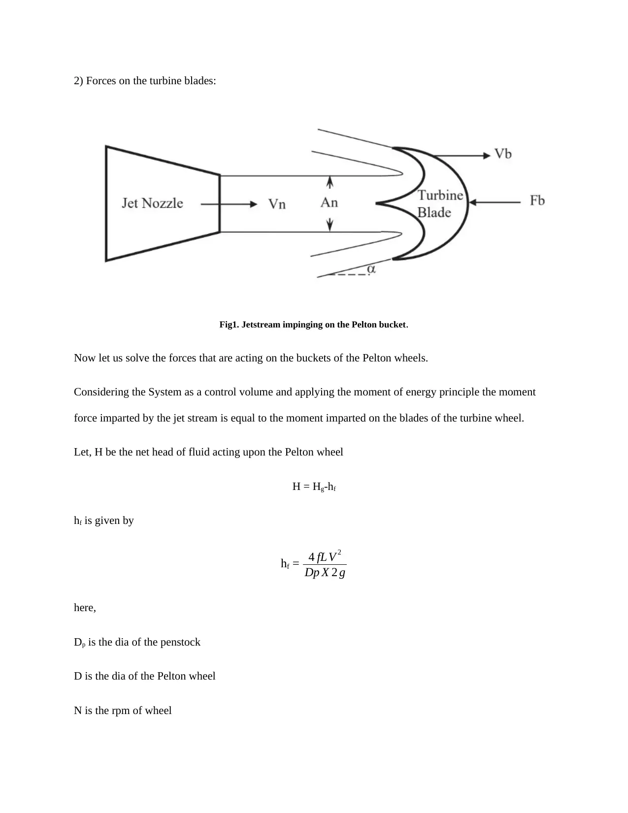
|4
|810
|69
Homework Assignment
AI Summary
This assignment evaluates the feasibility of utilizing a Pelton turbine design in an aircraft gas turbine engine, contrasting its typical use in hydroelectric power generation with the requirements of aircraft propulsion. It explains why applying a Pelton turbine, which relies on converting the kinetic energy of a water jet, is not suitable for a gas turbine that operates on the Brayton cycle. The analysis emphasizes that the back pressure generated by adding Pelton blades would reduce the engine's efficiency and thrust. Furthermore, the document derives equations for the forces acting on the turbine blades, considering factors such as fluid density, jet velocity, blade velocity, and deviation angle, ultimately determining the net force and work done by the jet stream on the blades.
1 out of 4

Your All-in-One AI-Powered Toolkit for Academic Success.
+13062052269
info@desklib.com
Available 24*7 on WhatsApp / Email
![[object Object]](/_next/static/media/star-bottom.7253800d.svg)
Copyright © 2020–2026 A2Z Services. All Rights Reserved. Developed and managed by ZUCOL.