Penstock Design for Pumped Storage: Structural Integrity Assessment

Verified

Added on  2023/06/14

|16
|2643
|353
Report
AI Summary
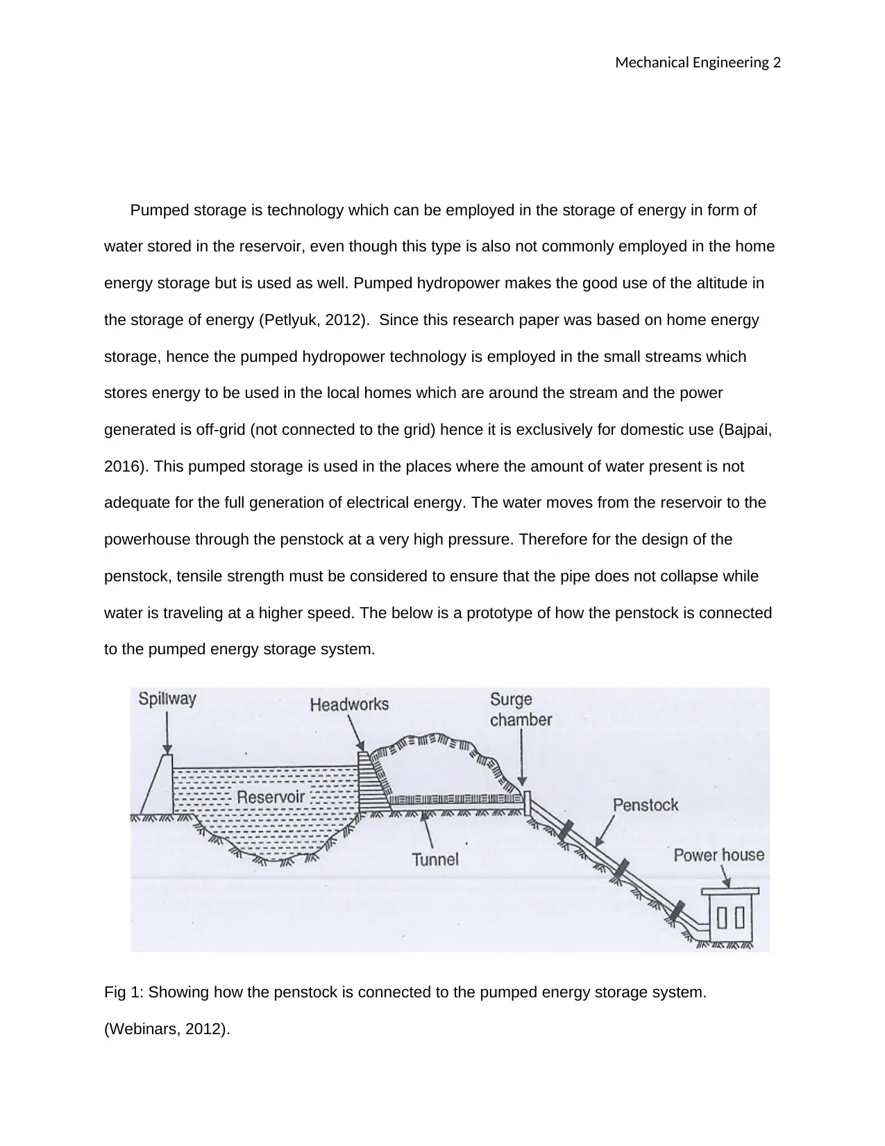
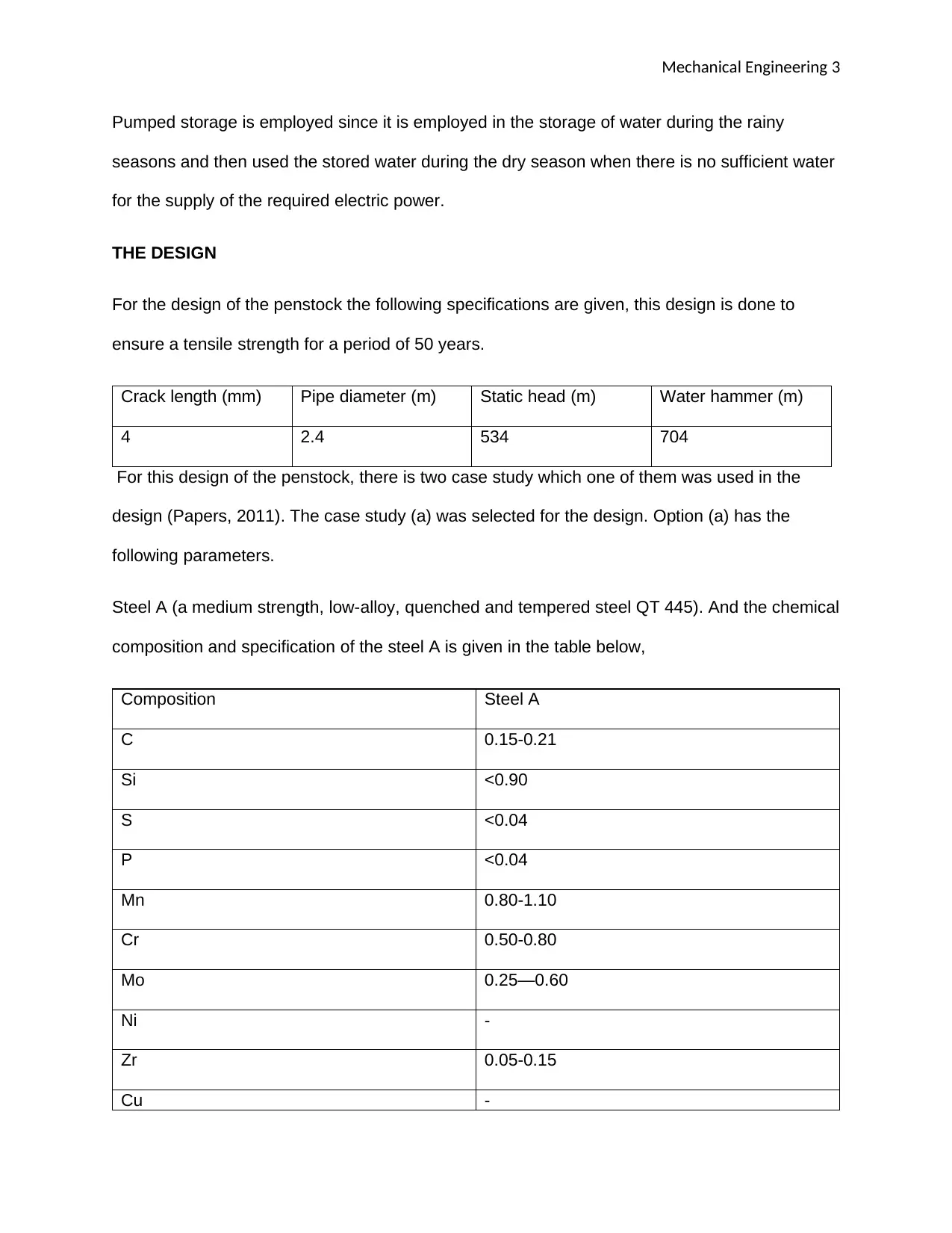
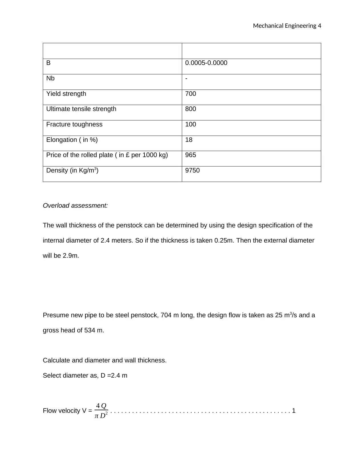
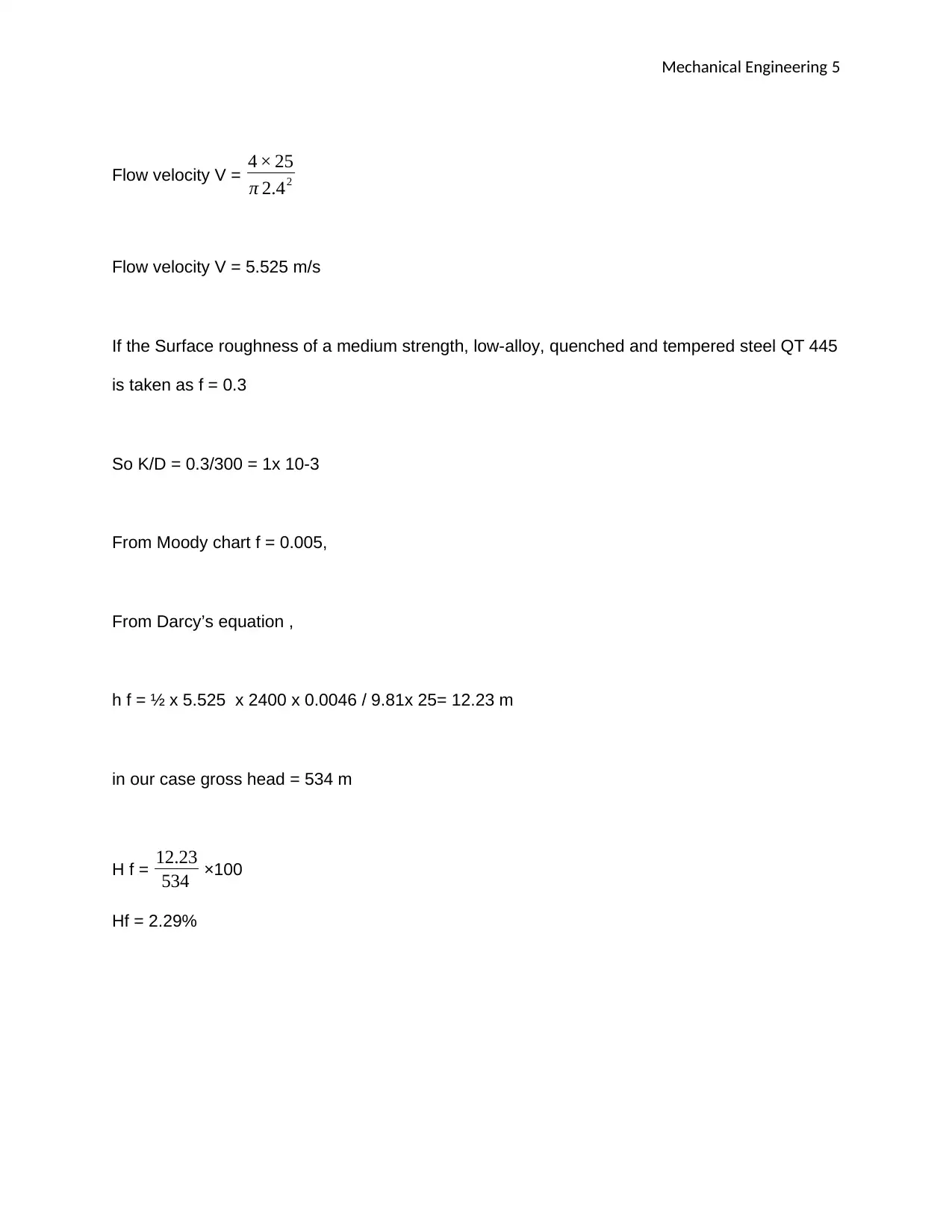
This report provides a detailed analysis of penstock design for pumped storage systems, focusing on structural integrity and crack assessment. It begins by introducing pumped storage technology and its application in local energy systems. The design process includes overload and fracture assessments, utilizing steel QT 445 and considering factors like crack length, pipe diameter, and static head. The report employs fracture assessment diagrams (FAD) and non-destructive testing (NDT) methods to evaluate crack-like defects and ensure the penstock's structural integrity. A life assessment estimates the fatigue lifetime, followed by a revision assessment suggesting increased thickness for enhanced strength. The report also examines defect geometry, analyzes crack size using relevant equations, and applies the Paris equation to estimate crack growth, concluding with considerations for thin-walled vessels and stress analysis. Desklib offers a variety of solved assignments and past papers to aid students in their studies.
Document Page
Mechanical Engineering 1
MECHANICAL ENGINEERING
By Name
Course
Instructor
Institution
Location
Date
tabler-icon-diamond-filled.svg

Paraphrase This Document

Need a fresh take? Get an instant paraphrase of this document with our AI Paraphraser
Document Page
Mechanical Engineering 2
Pumped storage is technology which can be employed in the storage of energy in form of
water stored in the reservoir, even though this type is also not commonly employed in the home
energy storage but is used as well. Pumped hydropower makes the good use of the altitude in
the storage of energy (Petlyuk, 2012). Since this research paper was based on home energy
storage, hence the pumped hydropower technology is employed in the small streams which
stores energy to be used in the local homes which are around the stream and the power
generated is off-grid (not connected to the grid) hence it is exclusively for domestic use (Bajpai,
2016). This pumped storage is used in the places where the amount of water present is not
adequate for the full generation of electrical energy. The water moves from the reservoir to the
powerhouse through the penstock at a very high pressure. Therefore for the design of the
penstock, tensile strength must be considered to ensure that the pipe does not collapse while
water is traveling at a higher speed. The below is a prototype of how the penstock is connected
to the pumped energy storage system.
Fig 1: Showing how the penstock is connected to the pumped energy storage system.
(Webinars, 2012).
Document Page
Mechanical Engineering 3
Pumped storage is employed since it is employed in the storage of water during the rainy
seasons and then used the stored water during the dry season when there is no sufficient water
for the supply of the required electric power.
THE DESIGN
For the design of the penstock the following specifications are given, this design is done to
ensure a tensile strength for a period of 50 years.
Crack length (mm) Pipe diameter (m) Static head (m) Water hammer (m)
4 2.4 534 704
For this design of the penstock, there is two case study which one of them was used in the
design (Papers, 2011). The case study (a) was selected for the design. Option (a) has the
following parameters.
Steel A (a medium strength, low-alloy, quenched and tempered steel QT 445). And the chemical
composition and specification of the steel A is given in the table below,
Composition Steel A
C 0.15-0.21
Si <0.90
S <0.04
P <0.04
Mn 0.80-1.10
Cr 0.50-0.80
Mo 0.25—0.60
Ni -
Zr 0.05-0.15
Cu -
Document Page
Mechanical Engineering 4
B 0.0005-0.0000
Nb -
Yield strength 700
Ultimate tensile strength 800
Fracture toughness 100
Elongation ( in %) 18
Price of the rolled plate ( in £ per 1000 kg) 965
Density (in Kg/m3) 9750
Overload assessment:
The wall thickness of the penstock can be determined by using the design specification of the
internal diameter of 2.4 meters. So if the thickness is taken 0.25m. Then the external diameter
will be 2.9m.
Presume new pipe to be steel penstock, 704 m long, the design flow is taken as 25 m3/s and a
gross head of 534 m.
Calculate and diameter and wall thickness.
Select diameter as, D =2.4 m
Flow velocity V = 4 Q
π D2 . . . . . . . . . . . . . . . . . . . . . . . . . . . . . . . . . . . . . . . . . . . . . . . . . . 1
tabler-icon-diamond-filled.svg

Paraphrase This Document

Need a fresh take? Get an instant paraphrase of this document with our AI Paraphraser
Document Page
Mechanical Engineering 5
Flow velocity V = 4 × 25
π 2.42
Flow velocity V = 5.525 m/s
If the Surface roughness of a medium strength, low-alloy, quenched and tempered steel QT 445
is taken as f = 0.3
So K/D = 0.3/300 = 1x 10⁻³
From Moody chart f = 0.005,
From Darcy’s equation ,
h f = ½ x 5.525 x 2400 x 0.0046 / 9.81x 25= 12.23 m
in our case gross head = 534 m
H f = 12.23
534 ×100
Hf = 2.29%
Document Page
Mechanical Engineering 6
Therefore with the above specifications, water which flows at a velocity of 5.525 m/s. This
velocity can safely increase by 2.29% without the breakage of the penstock (Nelson, 2014).
Therefore the maximum velocity is
102.29
100 × 5.525 = 5.6515m/s.
Fracture assessment:
The fracture assessment can be analysed using the following equation,
Kic= ɤα πac . . . . . . . . . . . . . . . . . . . . . . . . . . . . . . . . . . . . . . . . . . . . . . . . . . . . . . . . . . . . . . . .
2
Where Kic is Fracture toughness, α is applied engineering stress, ac is the crack size and ɤ is
the geometrical factor.
Crack length is taken to be more than 15 mm hence 20mm was employed. Stress is 70 MPa.
Therefore the value of geometric factor can be determined from the equation 2 above (McMurry,
2015).
Kic= ɤ×70000000 π × 0.02 = 100
ɤ×70000000 3.142× 0.02 = 100
ɤ×70000000×0.2506 = 100
17547535 ɤ= 100
ɤ=5.698 ×10⁻⁶
Document Page
Mechanical Engineering 7
Therefore during the design, the steel of the option A should have the ɤ of 5.698 ×10⁻⁶ according
to the design specifications (McMurry, 2015).
FAD
Once the mechanical and fracture toughness properties of the penstock are determined
experimentally, the next point involves in the structural integrity assessment of penstock pipe
having crack-like defects under different loading conditions (Pardalos, 2008). Failure
assessment diagram (FAD) can be well analyzed by the following equation.
Kr= Applied stress intergrity factor
Material fracture tougg h ness = K 1( a , α )
Kmatt . s. . . . . . . . . . . . . . . . . . . . . . . . . . . . . . . . . . . .
. . 3
Kr is the integrity of the steel.
Kr= 5.698× 106 × 70000000× 0.02
100
Kr= 5.698× 106 × 70000000× 0.02
100
Kr= 7.9772
100
Kr=0.07977
tabler-icon-diamond-filled.svg

Paraphrase This Document

Need a fresh take? Get an instant paraphrase of this document with our AI Paraphraser
Document Page
Mechanical Engineering 8
Therefore, the integrity of the material is proportional to the crack of the penstock, this is shown
in equation 3 above.
NDT
None Destructive Testing methods may be employed to assess the accuracy of the fracture
assessment of the penstock design material (Brown, 2015).
This method of assessment is basically done through the use of either the naked eyes or the
use of the camera to fully assess the perfection of the design and check keenly on the crack
and see if it is okay and will work best for the penstock. This can be illustrated in the figure
below;
Fig 2: Showing the use of inspection as a method of NDT
In some cases, radiations like x-rays are employed to aid the correct testing of the cracks in the
penstock (Petlyuk, 2012). This can be illustrated by the following diagram.
Document Page
Mechanical Engineering 9
Fig3: Showing x-rays employed in the NDT method
Most of the NDT methods are very accurate since they can access very minute cracks which
are in form of micrometers. Therefore there are very accurate, they are almost 95% accurate in
assessing the crack fractures in the penstock.
The shape of the crack will as well determine the sensitivity of the determining the crack in the
penstock (Bilmate, 2013). The cracks which are very straight are very difficult to determine
while those cracks which are bent or somehow curve can be easily assessed. And in some
cases, they can be assessed through NDT (observation through naked eyes) depending on the
size of the fracture (Bajpai, 2016). And in most cases, other NDT like x-rays can be employed to
fully assess it.
Life assessment
The penstock is designed to last for at least 5 years.
Nf= ( 3 Pmax
2 A × 0.895 Lc ) 1/T
Where A= Cross-section area of the penstock
Document Page
Mechanical Engineering 10
Pmax= maximum stress =70 Mpa
T= Period of time = 5 years
Lc= is the length of the penstock = 704 m
Nf = Number of cycles
A= πr2
A=3.142×1.22
A=4.52448
Nf= ( 3 ×70000000
2× 4.52448 ×0.895 ×704 ) 1/5
Nf= ( 210000000
5701.568 ) 1/5
Nf= ( 14491.3
5701.568 ) 1/5
Nf= (2.541) 1/5
Nf= 1.205 Cycles.
tabler-icon-diamond-filled.svg

Paraphrase This Document

Need a fresh take? Get an instant paraphrase of this document with our AI Paraphraser
Document Page
Mechanical Engineering 11
For the fatigue lifetime estimated to be for a period of 5 years, it will have a cycle of 1.205
cycles.
Revise assessment:
The thickness of the penstock for the design is taken as 0.25 m, but this design specification of
the thickness can be increased to aid in the strength of the penstock. The increase of the
thickness of the penstock will not only increase the strength but also increase the lifetime of the
penstock. If this thickness of 0.25 m is may be increased to 0.5 m then the cost of the material
is increased twice (Bany, 2012). The fatigue lifetime will also be increased hence the cycles will
be increased for the same period of time.
Defect geometry:
Mild steel is likely the most widely utilized penstock material for small hydro systems (Bhatt,
2012). Its low cost and ease of acquisition add to its appeal. Mild steel provides a greater
versatility for pipe diameter and thickness. It has moderate friction loss. Mild steel penstocks are
resistant to mechanical damage but can be more susceptible to corrosion when the pipelines
are buried. While these pipes are heavy, they can easily be manufactured in smaller segments.
The hoop stress which is created by the water flowing through the penstock affecting the edge
crack of the penstock. The calibration function for the geometry of the edge crack of the known
width plate of the tension caused by the flowing water (Williams, 2013). The surface of the
penstock would break easily when it is semi-elliptical. The semi-elliptical lying parallel penstock
Document Page
Mechanical Engineering 12
crack to the axis of the penstock is more prone to cracking than a perfect circle (Richard, 2013).
This is due to the pressure exerted to the walls of the pipe is more for the semi-elliptical as
compared to that of a perfect circle (Ramesh, 2011). The figure below shows the steel
employed in the construction of the penstock.
Fig 4: Showing the steel used in constructing the penstock.
The geometry calibration function Y varies with the crack size
The crack size (ac) can be obtained using the following non-linear algebraic equation
𝐾𝐼𝑐=𝑌𝜎𝜋𝑎𝑐 = 100
chevron_up_icon
1 out of 16
circle_padding
hide_on_mobile
zoom_out_icon
[object Object]