Project: Advanced Penstock Design for Hydroelectric Power Generation
VerifiedAdded on 2023/06/12
|16
|2793
|140
Project
AI Summary
This project proposal outlines the design of a robust penstock for hydroelectric power generation, emphasizing the importance of a stronger, pressure-resistant conduit to enhance electrical energy production and reduce maintenance costs. It reviews the background of pumped storage systems, where water is stored and released through the penstock to drive turbines and generate electricity. The design considerations include tensile strength to prevent collapse under high water pressure. The proposal highlights the significance of optimizing penstock design to increase power generation and minimize costs, referencing materials like mild steel and various testing methodologies. The methodology section details calculations for determining wall thickness, flow velocity, and fracture assessment using specific steel properties and equations. Non-Destructive Testing (NDT) methods are discussed for assessing the accuracy of the design, including visual inspection and x-ray analysis. The project also considers defect geometry and the impact of hoop stress on crack formation, ultimately aiming for a durable penstock capable of withstanding high-speed water flow over an extended period.

Designing a penstock 1
DESIGNING A PENSTOCK
By Name
Course
Instructor
Institution
Location
Date
DESIGNING A PENSTOCK
By Name
Course
Instructor
Institution
Location
Date
Paraphrase This Document
Need a fresh take? Get an instant paraphrase of this document with our AI Paraphraser
Designing a penstock 2
ABSTRACT
In hydroelectric power, penstock is very vital for the operation since it is through this
penstock that water at a very high speed travels from the reservoir to the powerhouse to help
generate electrical power. In this project proposal, a stronger and pressure resistance penstock is
proposed for the design. A stronger penstock will ensure more electrical energy is produced
since it can withstand that high pressure of water flowing from the reservoir to the powerhouse.
A stronger penstock will as well help to reduce the cost of maintenance in the hydroelectric
power stations.
Designing a penstock 3
INTRODUCTION
Background information
Pumped storage is mechanism that can be used in the storage of electrical energy in form of
water stored in the reservoir. The water moves from the reservoir to the powerhouse through the
penstock at a very high pressure. In pumped hydroelectric power, there is some water which is
stored in the reservoir, this water will then be released through the penstock to the powerhouse at
a very high speed. In the powerhouse, the high-speed water is directed to the water turbines
which will then rotate and in turn rotates the generators which are coupled with the turbines. This
then will result in the generation of electrical power. 3wTherefore for the design of the penstock,
tensile strength must be considered to ensure that the pipe does not collapse while water is
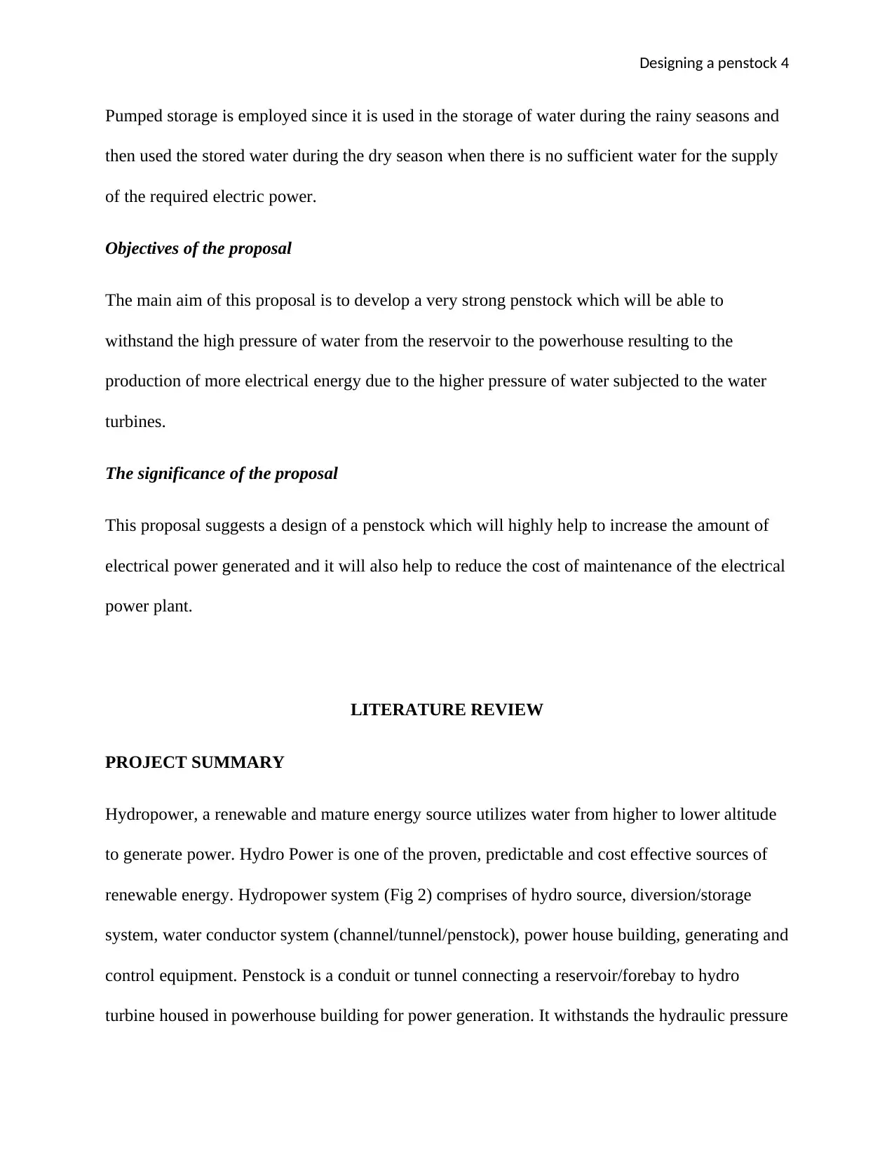
traveling at a higher speed. The below is a prototype of how the penstock is connected to the
pumped energy storage system.
Fig 1: Showing how the penstock is connected to the pumped energy storage system. (Webinars,
2012).
⊘ This is a preview!⊘
Do you want full access?
Subscribe today to unlock all pages.

Trusted by 1+ million students worldwide
Designing a penstock 4
Pumped storage is employed since it is used in the storage of water during the rainy seasons and
then used the stored water during the dry season when there is no sufficient water for the supply
of the required electric power.
Objectives of the proposal
The main aim of this proposal is to develop a very strong penstock which will be able to
withstand the high pressure of water from the reservoir to the powerhouse resulting to the
production of more electrical energy due to the higher pressure of water subjected to the water
turbines.
The significance of the proposal
This proposal suggests a design of a penstock which will highly help to increase the amount of
electrical power generated and it will also help to reduce the cost of maintenance of the electrical
power plant.
LITERATURE REVIEW
PROJECT SUMMARY
Hydropower, a renewable and mature energy source utilizes water from higher to lower altitude
to generate power. Hydro Power is one of the proven, predictable and cost effective sources of
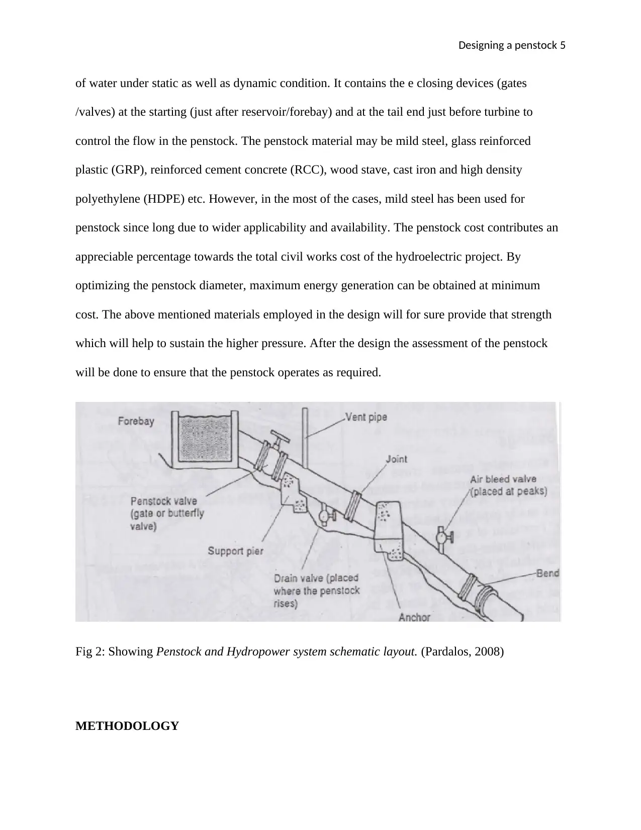
renewable energy. Hydropower system (Fig 2) comprises of hydro source, diversion/storage
system, water conductor system (channel/tunnel/penstock), power house building, generating and
control equipment. Penstock is a conduit or tunnel connecting a reservoir/forebay to hydro
turbine housed in powerhouse building for power generation. It withstands the hydraulic pressure
Paraphrase This Document
Need a fresh take? Get an instant paraphrase of this document with our AI Paraphraser
Designing a penstock 5
of water under static as well as dynamic condition. It contains the e closing devices (gates
/valves) at the starting (just after reservoir/forebay) and at the tail end just before turbine to
control the flow in the penstock. The penstock material may be mild steel, glass reinforced
plastic (GRP), reinforced cement concrete (RCC), wood stave, cast iron and high density
polyethylene (HDPE) etc. However, in the most of the cases, mild steel has been used for
penstock since long due to wider applicability and availability. The penstock cost contributes an
appreciable percentage towards the total civil works cost of the hydroelectric project. By
optimizing the penstock diameter, maximum energy generation can be obtained at minimum
cost. The above mentioned materials employed in the design will for sure provide that strength
which will help to sustain the higher pressure. After the design the assessment of the penstock
will be done to ensure that the penstock operates as required.
Fig 2: Showing Penstock and Hydropower system schematic layout. (Pardalos, 2008)
METHODOLOGY
Designing a penstock 6
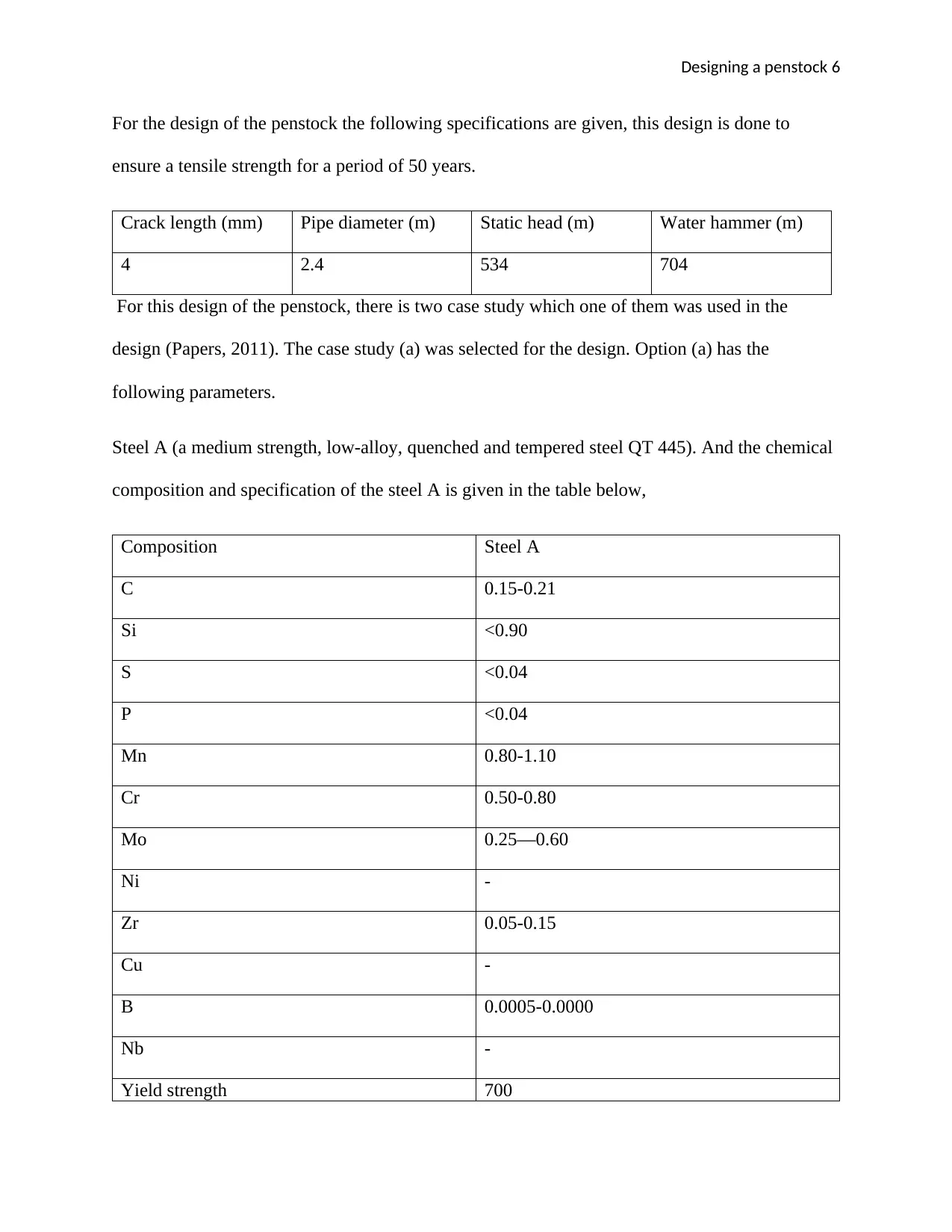
For the design of the penstock the following specifications are given, this design is done to
ensure a tensile strength for a period of 50 years.
Crack length (mm) Pipe diameter (m) Static head (m) Water hammer (m)
4 2.4 534 704
For this design of the penstock, there is two case study which one of them was used in the
design (Papers, 2011). The case study (a) was selected for the design. Option (a) has the
following parameters.
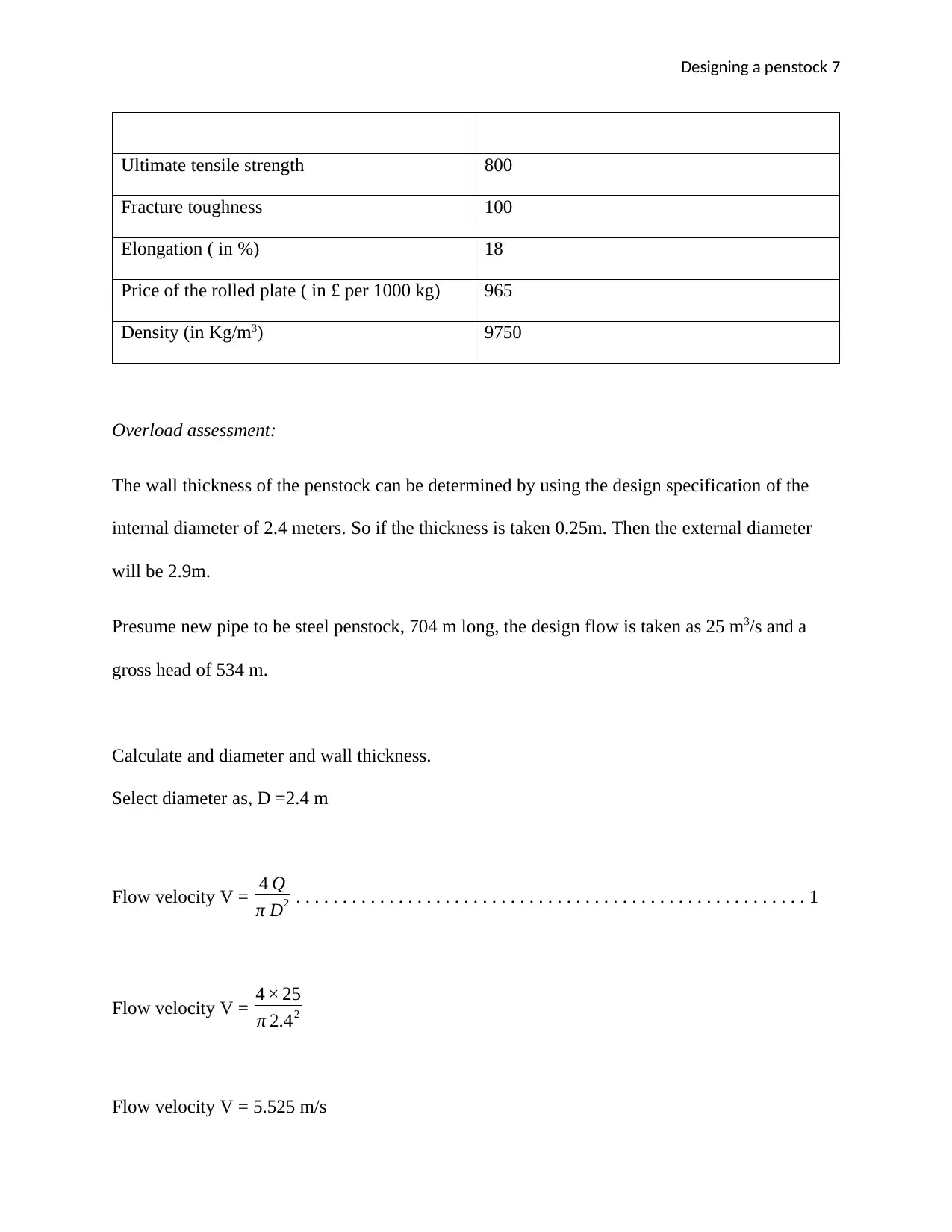
Steel A (a medium strength, low-alloy, quenched and tempered steel QT 445). And the chemical
composition and specification of the steel A is given in the table below,
Composition Steel A
C 0.15-0.21
Si <0.90
S <0.04
P <0.04
Mn 0.80-1.10
Cr 0.50-0.80
Mo 0.25—0.60
Ni -
Zr 0.05-0.15
Cu -
B 0.0005-0.0000
Nb -
Yield strength 700
⊘ This is a preview!⊘
Do you want full access?
Subscribe today to unlock all pages.

Trusted by 1+ million students worldwide
Designing a penstock 7
Ultimate tensile strength 800
Fracture toughness 100
Elongation ( in %) 18
Price of the rolled plate ( in £ per 1000 kg) 965
Density (in Kg/m3) 9750
Overload assessment:
The wall thickness of the penstock can be determined by using the design specification of the
internal diameter of 2.4 meters. So if the thickness is taken 0.25m. Then the external diameter
will be 2.9m.
Presume new pipe to be steel penstock, 704 m long, the design flow is taken as 25 m3/s and a
gross head of 534 m.
Calculate and diameter and wall thickness.
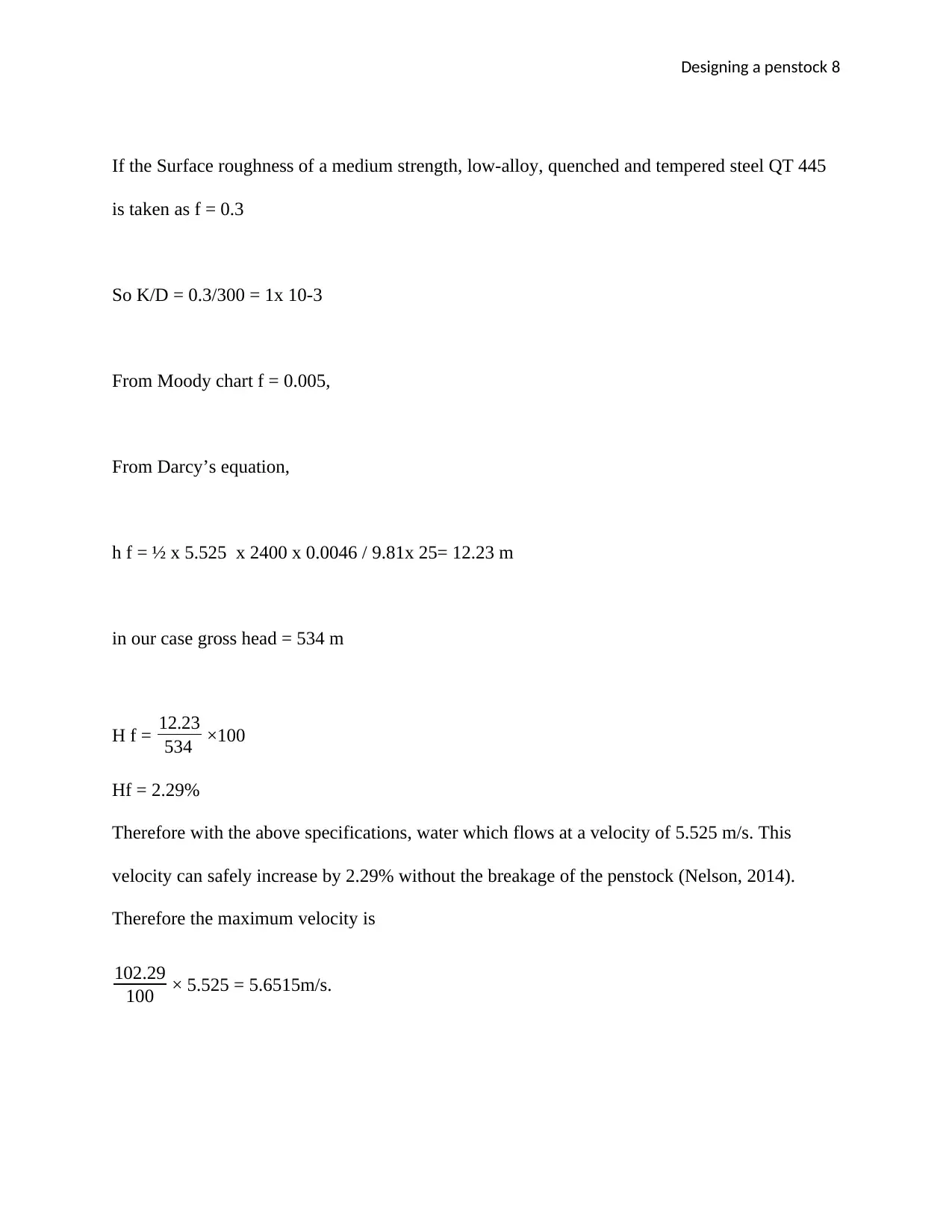
Select diameter as, D =2.4 m
Flow velocity V = 4 Q
π D2 . . . . . . . . . . . . . . . . . . . . . . . . . . . . . . . . . . . . . . . . . . . . . . . . . . . . . . . 1
Flow velocity V = 4 × 25
π 2.42
Flow velocity V = 5.525 m/s
Paraphrase This Document
Need a fresh take? Get an instant paraphrase of this document with our AI Paraphraser
Designing a penstock 8
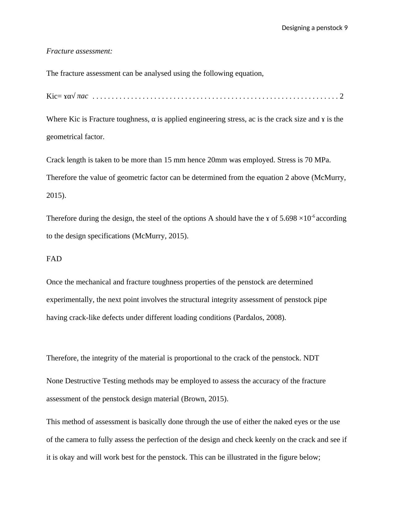
If the Surface roughness of a medium strength, low-alloy, quenched and tempered steel QT 445
is taken as f = 0.3
So K/D = 0.3/300 = 1x 10⁻³
From Moody chart f = 0.005,
From Darcy’s equation,
h f = ½ x 5.525 x 2400 x 0.0046 / 9.81x 25= 12.23 m
in our case gross head = 534 m
H f = 12.23
534 ×100
Hf = 2.29%
Therefore with the above specifications, water which flows at a velocity of 5.525 m/s. This
velocity can safely increase by 2.29% without the breakage of the penstock (Nelson, 2014).
Therefore the maximum velocity is
102.29
100 × 5.525 = 5.6515m/s.
Designing a penstock 9
Fracture assessment:
The fracture assessment can be analysed using the following equation,
Kic= ɤα√ πac . . . . . . . . . . . . . . . . . . . . . . . . . . . . . . . . . . . . . . . . . . . . . . . . . . . . . . . . . . . . . . . . 2
Where Kic is Fracture toughness, α is applied engineering stress, ac is the crack size and ɤ is the
geometrical factor.
Crack length is taken to be more than 15 mm hence 20mm was employed. Stress is 70 MPa.
Therefore the value of geometric factor can be determined from the equation 2 above (McMurry,
2015).
Therefore during the design, the steel of the options A should have the ɤ of 5.698 ×10⁻⁶ according
to the design specifications (McMurry, 2015).
FAD
Once the mechanical and fracture toughness properties of the penstock are determined
experimentally, the next point involves the structural integrity assessment of penstock pipe
having crack-like defects under different loading conditions (Pardalos, 2008).
Therefore, the integrity of the material is proportional to the crack of the penstock. NDT
None Destructive Testing methods may be employed to assess the accuracy of the fracture
assessment of the penstock design material (Brown, 2015).
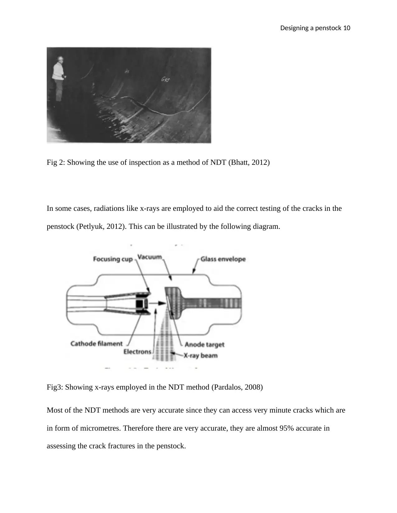
This method of assessment is basically done through the use of either the naked eyes or the use
of the camera to fully assess the perfection of the design and check keenly on the crack and see if
it is okay and will work best for the penstock. This can be illustrated in the figure below;
⊘ This is a preview!⊘
Do you want full access?
Subscribe today to unlock all pages.

Trusted by 1+ million students worldwide
Designing a penstock 10
Fig 2: Showing the use of inspection as a method of NDT (Bhatt, 2012)
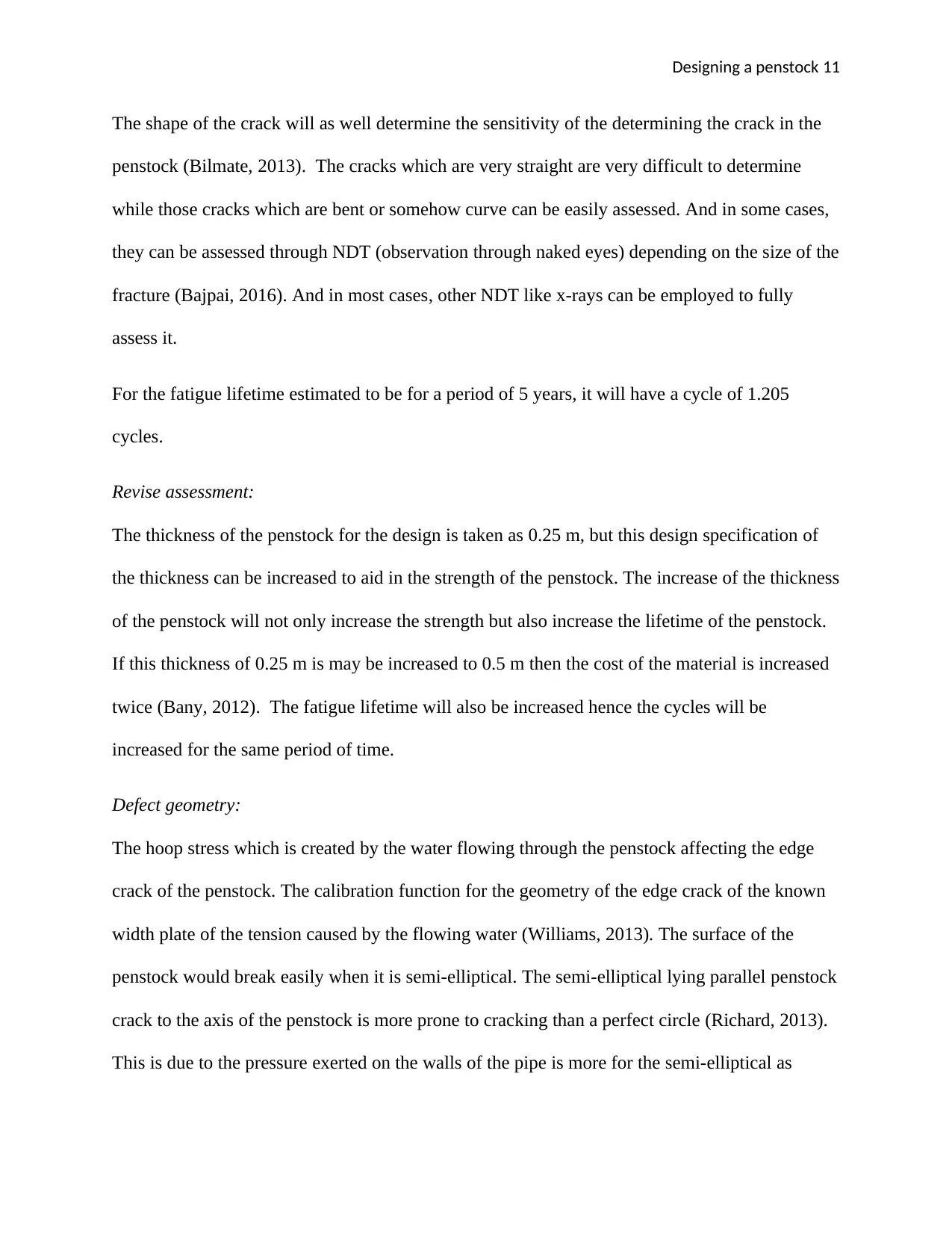
In some cases, radiations like x-rays are employed to aid the correct testing of the cracks in the
penstock (Petlyuk, 2012). This can be illustrated by the following diagram.
Fig3: Showing x-rays employed in the NDT method (Pardalos, 2008)
Most of the NDT methods are very accurate since they can access very minute cracks which are
in form of micrometres. Therefore there are very accurate, they are almost 95% accurate in
assessing the crack fractures in the penstock.
Paraphrase This Document
Need a fresh take? Get an instant paraphrase of this document with our AI Paraphraser
Designing a penstock 11
The shape of the crack will as well determine the sensitivity of the determining the crack in the
penstock (Bilmate, 2013). The cracks which are very straight are very difficult to determine
while those cracks which are bent or somehow curve can be easily assessed. And in some cases,
they can be assessed through NDT (observation through naked eyes) depending on the size of the
fracture (Bajpai, 2016). And in most cases, other NDT like x-rays can be employed to fully
assess it.
For the fatigue lifetime estimated to be for a period of 5 years, it will have a cycle of 1.205
cycles.
Revise assessment:
The thickness of the penstock for the design is taken as 0.25 m, but this design specification of
the thickness can be increased to aid in the strength of the penstock. The increase of the thickness
of the penstock will not only increase the strength but also increase the lifetime of the penstock.
If this thickness of 0.25 m is may be increased to 0.5 m then the cost of the material is increased
twice (Bany, 2012). The fatigue lifetime will also be increased hence the cycles will be
increased for the same period of time.
Defect geometry:
The hoop stress which is created by the water flowing through the penstock affecting the edge
crack of the penstock. The calibration function for the geometry of the edge crack of the known
width plate of the tension caused by the flowing water (Williams, 2013). The surface of the
penstock would break easily when it is semi-elliptical. The semi-elliptical lying parallel penstock
crack to the axis of the penstock is more prone to cracking than a perfect circle (Richard, 2013).
This is due to the pressure exerted on the walls of the pipe is more for the semi-elliptical as
Designing a penstock 12
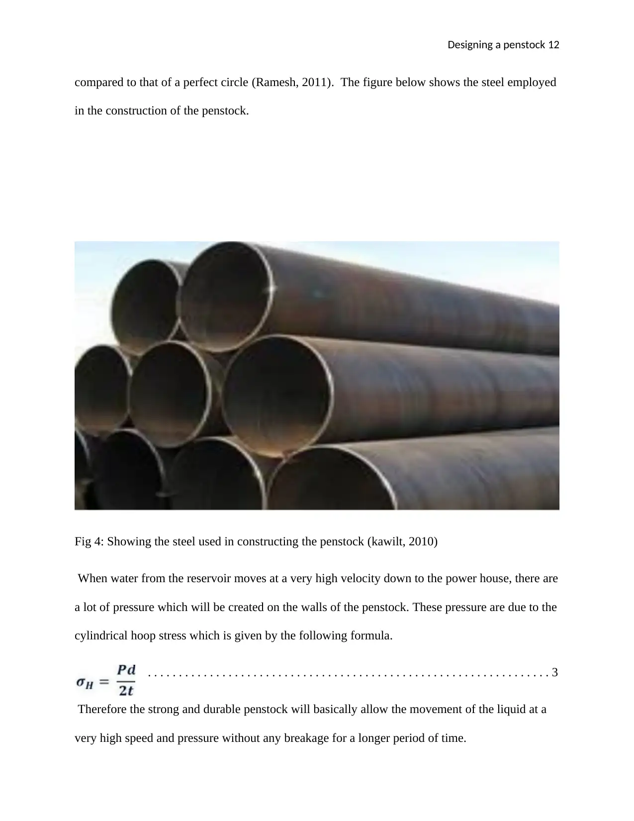
compared to that of a perfect circle (Ramesh, 2011). The figure below shows the steel employed
in the construction of the penstock.
Fig 4: Showing the steel used in constructing the penstock (kawilt, 2010)
When water from the reservoir moves at a very high velocity down to the power house, there are
a lot of pressure which will be created on the walls of the penstock. These pressure are due to the
cylindrical hoop stress which is given by the following formula.
. . . . . . . . . . . . . . . . . . . . . . . . . . . . . . . . . . . . . . . . . . . . . . . . . . . . . . . . . . . . . . . . . 3
Therefore the strong and durable penstock will basically allow the movement of the liquid at a
very high speed and pressure without any breakage for a longer period of time.
⊘ This is a preview!⊘
Do you want full access?
Subscribe today to unlock all pages.

Trusted by 1+ million students worldwide
1 out of 16
Related Documents
Your All-in-One AI-Powered Toolkit for Academic Success.
+13062052269
info@desklib.com
Available 24*7 on WhatsApp / Email
![[object Object]](/_next/static/media/star-bottom.7253800d.svg)
Unlock your academic potential
Copyright © 2020–2026 A2Z Services. All Rights Reserved. Developed and managed by ZUCOL.


