Performance Analysis of Novel Converter for PV and Battery Systems
VerifiedAdded on 2020/12/07
|21
|6791
|347
Project
AI Summary
This document presents a synopsis of a PhD thesis focused on the performance analysis of a novel single-stage interconnected converter and power flow control method for PV and battery-powered EHV systems. The research investigates the application of this converter in Photovoltaic (PV) and battery-powered systems, particularly in the context of Electric Hybrid Vehicles (EHV). The study aims to improve energy efficiency and reduce greenhouse gas emissions. The objectives include designing a converter with reduced power semiconductor devices to minimize losses, evaluating its dynamic performance, managing power flow between PV and battery systems, enhancing overall efficiency through single-stage power conversion, and improving the driving efficiency of EVs using fuzzy logic and ANN-based regenerative braking systems. The research contribution involves the design, analysis, and performance evaluation of the novel converter, comparing it with conventional converters and exploring its application in different operating domains. The study also introduces a fuzzy logic controller for regenerative braking, improving driving efficiency and performance. Additionally, an ANN-based regenerative braking system is proposed for further enhancement. The literature review covers various converter topologies, control techniques, and regenerative braking strategies. The project uses MATLAB Simulink for performance assessment, evaluating speed, stator current and voltage, and battery state. The research seeks to address the limitations of conventional converters, such as high conduction losses and complex designs, by proposing a more compact and efficient solution for PV-battery powered EV systems. The research also analyzes the implementation of fuzzy logic and ANN based regenerative braking systems for improving the performance of electric vehicles.
SYNOPSIS OF THESIS
PERFORMANCE ANALYSIS OF A NOVEL
SINGLE STAGE INTERCONNECTED
CONVERTER AND POWER FLOW CONTROL
METHOD FOR PV AND BATTERY POWERED
EHV SYSTEMS
A SYNOPSIS
Submitted by
JAMBULINGAM. S.
Registration Number: 0114909204
in partial fulfillment of the requirements for the degree of
DOCTOR OF PHILOSOPHY
Under the Supervision of
Dr. D. M. MARY SYNTHIA REGIS PRABHA
DEPARTMENT OF ELECTRICAL & ELECTRONICS
ENGINEERING
NOORUL ISLAM CENTRE FOR HIGHER EDUCATION
(Deemed-to-be-University under section 3 of the U.G.C. Act 1956)
Accredited by NAAC with ‘A’ Grade
KUMARACOIL, KANYAKUMARI DISTRICT,
TAMILNADU, INDIA - 629 180
OCTOBER - 2020
Paraphrase This Document
Need a fresh take? Get an instant paraphrase of this document with our AI Paraphraser
PERFORMANCE ANALYSIS OF A NOVEL SINGLE STAGE
INTERCONNECTED CONVERTER AND POWER FLOW CONTROL
METHOD FOR PV AND BATTERY POWERED EHV SYSTEMS
1. INTRODUCTION
The rapid change in global energy demands and the environmental
problems caused by fossil fuels have resulted in the need of solar energy which
becomes a potential solution and is one amongst the most popular renewable energy
sources. However, Photovoltaic (PV) energy has some boundaries such as high cost
of capitation and low conversion efficiency, but it has grasped the interest of the
researchers Wang et al., (2013). The PV system comprises a friendly environment
and it is an alternative method for production of energy by utilising the energy from
the sun. Without any noise and emissions it can operate, even if the load is increased.
The output from a solar PV cell is a DC, in which the magnitude of such
output current is always calculated by the PV cell area and the amount of solar
irradiation exposed. The magnitude of output voltage from the individual solar cell is
normally in the range of 0.5V.These cells are generally connected in a series manner
in order to comprise modules with a realistic level of voltage. When the magnitude of
PV system and load resistance is equal, then maximum power is delivered at the
operating point. This can be achieved by an interfacing DC-DC power converter
utilizing some assured techniques of MPPT.
Among the various types of arrangements of photovoltaic technology, a
stand-alone PV-battery-powered backup system can be utilised in different types of
applications Chen et al., (2013). For maintaining the system operation, the energy
stored can be helpful during the shading to the PV panel. In such cases, to keep the
power demand an efficient converter is required within the limit of the maximum
availability and to prevent any failure, and shut down or damage. To diminish these
problems, a novel single stage Interconnected converter named Modified Boost
Bidirectional Buck-Boost Converter (MB4C) is proposed.
2
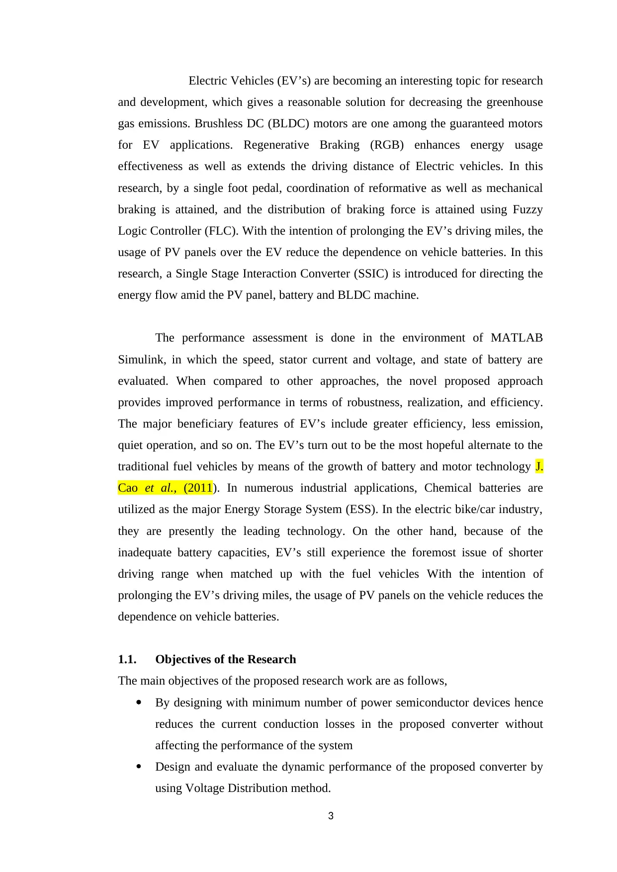
Electric Vehicles (EV’s) are becoming an interesting topic for research
and development, which gives a reasonable solution for decreasing the greenhouse
gas emissions. Brushless DC (BLDC) motors are one among the guaranteed motors
for EV applications. Regenerative Braking (RGB) enhances energy usage
effectiveness as well as extends the driving distance of Electric vehicles. In this
research, by a single foot pedal, coordination of reformative as well as mechanical
braking is attained, and the distribution of braking force is attained using Fuzzy
Logic Controller (FLC). With the intention of prolonging the EV’s driving miles, the
usage of PV panels over the EV reduce the dependence on vehicle batteries. In this
research, a Single Stage Interaction Converter (SSIC) is introduced for directing the
energy flow amid the PV panel, battery and BLDC machine.
The performance assessment is done in the environment of MATLAB
Simulink, in which the speed, stator current and voltage, and state of battery are
evaluated. When compared to other approaches, the novel proposed approach
provides improved performance in terms of robustness, realization, and efficiency.
The major beneficiary features of EV’s include greater efficiency, less emission,
quiet operation, and so on. The EV’s turn out to be the most hopeful alternate to the
traditional fuel vehicles by means of the growth of battery and motor technology J.
Cao et al., (2011). In numerous industrial applications, Chemical batteries are
utilized as the major Energy Storage System (ESS). In the electric bike/car industry,
they are presently the leading technology. On the other hand, because of the
inadequate battery capacities, EV’s still experience the foremost issue of shorter
driving range when matched up with the fuel vehicles With the intention of
prolonging the EV’s driving miles, the usage of PV panels on the vehicle reduces the
dependence on vehicle batteries.
1.1. Objectives of the Research
The main objectives of the proposed research work are as follows,
By designing with minimum number of power semiconductor devices hence
reduces the current conduction losses in the proposed converter without
affecting the performance of the system
Design and evaluate the dynamic performance of the proposed converter by
using Voltage Distribution method.
3
⊘ This is a preview!⊘
Do you want full access?
Subscribe today to unlock all pages.
Trusted by 1+ million students worldwide
Manage and control a strong power flow between PV and battery for electric
hybrid vehicle with proposed technology.
Increase the overall efficiency of the proposed converter by using a single
stage power conversion technique and compared with conventional converter
in terms of average losses and conversion efficiency.
Increase the driving efficiency and performance of the Electric Vehicle by
controlling the braking torque with a Fuzzy Logic based new regenerative
braking system and ANN based improved regenerative braking system.
1.2. RESEARCH CONTRIBUTION
This research work is mainly focused to design and analyze the performance of a
novel single stage Interconnected converter Chen et al., (2013) in a PV system. The
working principle of the proposed converter under various operating modes and
mathematical modelling are explained. The new control strategy for the proposed
system is also discussed.
The dynamic performance of the proposed converter can be evaluated by
implementing a three domain voltage distribution control method in terms of overall
component count, average losses and efficiency. Based on the solar radiation, they
are classified as Sun Domain (SD), Minimum Battery Charging Domain (MBCD)
and Maximum Battery Discharge Domain (MBDD). When the proposed converter is
operating under different domains, it has less number of conducting components
hence resulting in reduction of converter size and conduction losses thereby
improving the efficiency. It is also proved that the performance of the proposed
converter is superior when compared with other conventional converters while
operating in three distribution domains.
The strong power flow between PV port and battery port for Electric hybrid
vehicle can be controlled by using a single stage proposed interconnected converter.
The Fuzzy Logic based new regenerative braking system was implemented in order
to control the braking torque hence increase the driving efficiency and performance
of an Electric Vehicle. An Artificial Neural Network (ANN) based improved
regenerative braking system was suggested to control the braking torque hence
increase the driving efficiency and driving distance also performance of an Electric
Vehicle in terms of robustness and realization.
4
Paraphrase This Document
Need a fresh take? Get an instant paraphrase of this document with our AI Paraphraser
2. PROBLEM SPECIFICATION
From the literature survey, the dynamic performance of the conventional converter is
found to be poor due to more number of power semiconductor devices, there by
gaining a complex system design. Due to high current conduction losses the
efficiency of the converter is reduced. The conventional converter has a non-uniform
flow of current between battery and load port when the battery is connected for
charging and the life period of the battery is reduced. Because of these drawbacks,
they are not suitable for a PV-battery powered Electric Hybrid Vehicle system. This
could be rectified by using a boost bidirectional buck with buck boost converter
(MB4C) which decreases the usage of power devices and the whole system design is
found to be more compact.
The strong power flow management between PV and battery for Electric
vehicle can be controlled by using single stage proposed converter. A Fuzzy Logic
based new regenerative braking system is proposed to control the braking torque
hence increase the driving efficiency and performance of an Electric Vehicle. An
Artificial Neural Network (ANN) based Z. Chen et al., (2014) improved regenerative
braking system to control the braking torque hence increase the driving efficiency,
distance and performance of an Electric Vehicle in terms of strength and recognition.
3. LITERATURE SURVEY
A new systematic approach of deriving a three port converter from the fuel
bridge converter is proposed by Wu et al., (2012). The proposed converter can be
applied for renewable power system applications. A single stage power conversion
method is used to achieve high efficiency and also to reduce the number of power
devices used. But due to the high conduction losses, the conversion efficiency was
decreased. The pulse width modulation techniques are utilized to reduce the DC
biasing of the transformer.
Falcones et al., (2010) presented a novel control technique for a three-port
DC-DC converter based PV system with large storage capacity. The proposed
controller has the advantage of fast transient response and cross coupling
characteristics. The three port topology is used to obtain a transient journey from the
storage. The other conventional design techniques such as SISO (Single Input Single
5
Output) control design and Feed forward compensation are also presented. The
performance of the proposed control systems is verified against simulation results.
Chen, Wang et al., (2014) presented a novel micro-converter photovoltaic
system consisting of Buck-Boost converters connected in a series manner and a
central inverter. Each PV panel is able to work at its limited maximum power point.
The cascaded converter can function in buck or boost mode to comprehend the
output voltage of wide range. The power balance between the series-connected
converter and central inverter is maintained. A new updated procedure and safety
approach is also proposed to improve stabilization and to start the converters
continuously. The converter output voltage and control scheme are presented. The
simulation results are compared with experimental results and they prove the
advantages of the proposed control approach.
Balamurugan et al. (2012) presented a fuzzy logic controller to control and
tracking the maximum power for a combined PV and wind turbine system. The
hybrid integrated structure fed by PV and wind turbine sources suitable for
distributed generation is also proposed. Under all conditions, the proposed method is
capable of feeding a minimum amount of power to the power grid and working as an
uninterruptable power source. When the switches are turned on/off the efficiency of
conventional boost converter is reduced due to hard switching and produces losses.
The switching losses and voltage stress are reduced by the proposed switching
pattern.
Jiang et al., (2009) presented a comparative calculation of the existing control
methods for switch-mode converters suitable for PV applications. They are hysteresis
current control; current programmed control, average current control and nonlinear
carrier control methods under the load variations and input fluctuations. The static
and dynamic responses of the PV systems are examined and harmonic analysis is
also implemented.
Sahin et al., (2012) examined various control techniques to control the output
voltage of the DC-DC converter. The presented techniques are successfully
implemented and they are also proposed a technique with FLC. The techniques are
implemented for the buck-boost DC-DC converter useful for a PV battery-load
system. Two membership functions are used in the FLC to control the output voltage
of the converter and by using gauss membership functions the output voltage was
6
⊘ This is a preview!⊘
Do you want full access?
Subscribe today to unlock all pages.
Trusted by 1+ million students worldwide
very near to the reference voltage value, hence there is no overshoot and large
ripples.
XU GQ LI et al., (2011) proposed an intelligent regenerative braking strategy
for electric vehicles. Regenerative braking is an effective approach for electric
vehicles to extend their driving range. An ANN -based regenerative braking strategy
integrated with series regenerative braking is developed in this paper to advance the
level of energy-savings. From the viewpoint of securing car stability in braking
operations, the braking force distribution between the front and rear wheels so as to
accord with the ideal distribution curve are considered to prevent vehicles from
experiencing wheel lock and slip phenomena during braking.
S S Bhurse, et al., (2018) presented a new regenerative braking system which
is about extracting the kinetic energy which was wasted as heat from the wheels and
friction in conventional braking. This method is more efficient for vehicles moving at
higher speeds. The improvement was achieved by flywheel, ultra-capacitor,
advanced power electronic converter and efficient energy storage systems. The
regenerative braking improves the driving range around 16.25%. also then by using a
fuzzy RBS and the driver's braking force command, vehicle speed, battery SOC,
battery temperature are designed to determine the distribution between friction
braking force and regenerative braking force to improve the energy recuperation
efficiency.
Kiddee K et al., (2018) proposed a regenerative braking system strategy for
battery electric vehicles with a hybrid energy storage system driven by a brushless
DC motor. In the regenerative braking mode of Battery Electric Vehicle (BEV), and
the BLDC (Brushless D.C) motor works as a generator. The DC-link voltage is
boosted and regenerative braking energy is transported to a battery using a suitable
switching pattern. The energy stored in the HESS through reverse current flow can
be broken to improve acceleration and maintain the batteries from frequent deep
discharging during high power mode. In addition, the ANN based RBS control
mechanism was utilized to optimize the switching scheme of the vehicular breaking
force distribution. Different imitation and experiments were employed and carried
out to verify the performance of the proposed RBS strategy.
7
Paraphrase This Document
Need a fresh take? Get an instant paraphrase of this document with our AI Paraphraser

4. OVERVIEW OF THE THESIS
The first chapter clearly discusses the background of DC-DC converters
and their role in PV powered backup systems in order to increase the efficiency of
the proposed converter by reducing the number of power semiconductor components
and also current conduction losses.
The second chapter clearly discusses the design and performance analysis of
the Proposed Interconnected converter. Using Voltage Distribution control method
the performance evaluation of the proposed converter was done which improves the
dynamic performance of the proposed converter. The simulation execution of the
proposed converter is also presented.
The third chapter discusses the robust power flow between PV and battery
port for Electric vehicle using single stage proposed interconnected converter. A
Fuzzy Logic based new regenerative braking system is developed in order to control
the braking torque during regenerative braking thus increasing the driving efficiency
and performance of the Electric Vehicle.
The fourth chapter presents an Artificial Neural Network based new and
improved regenerative braking system to control the braking torque for increasing
the driving efficiency and performance of an Electric Vehicle. The simulation of the
converter is also presented.
The fifth chapter concludes the thesis, with the findings from the proposed
approaches. Moreover, it also discusses the forthcoming scope of the proposed
system for further improvement.
5. RESULTS AND DISCUSSION
The research work is summarized in the following three sections.
5.1. Working Principle and Performance Analysis of Proposed MB4C
The first section explains the working principle and performance
analysis of the proposed MB4C and also voltage based three domain control scheme
for the three port converter. The circuit diagram of the proposed converter is
presented in the Figure 1. Depending on the connection between PV generation
power and load demand power, MB4C can operate under various power flow modes.
The principles of circuit operation and analysis are illustrated with the subsequent
assumptions: 1) All switches are assumed to be ideal; 2) the capacitors are massive
enough in order that the voltage ripples owing to switch are negligible and will be
8
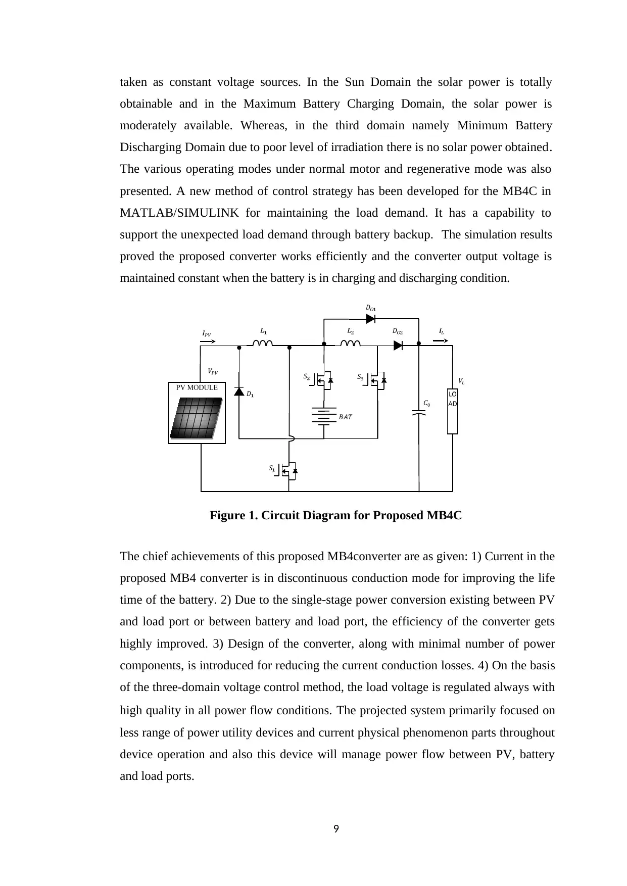
taken as constant voltage sources. In the Sun Domain the solar power is totally
obtainable and in the Maximum Battery Charging Domain, the solar power is
moderately available. Whereas, in the third domain namely Minimum Battery
Discharging Domain due to poor level of irradiation there is no solar power obtained.
The various operating modes under normal motor and regenerative mode was also
presented. A new method of control strategy has been developed for the MB4C in
MATLAB/SIMULINK for maintaining the load demand. It has a capability to
support the unexpected load demand through battery backup. The simulation results
proved the proposed converter works efficiently and the converter output voltage is
maintained constant when the battery is in charging and discharging condition.
Figure 1. Circuit Diagram for Proposed MB4C
The chief achievements of this proposed MB4converter are as given: 1) Current in the
proposed MB4 converter is in discontinuous conduction mode for improving the life
time of the battery. 2) Due to the single-stage power conversion existing between PV
and load port or between battery and load port, the efficiency of the converter gets
highly improved. 3) Design of the converter, along with minimal number of power
components, is introduced for reducing the current conduction losses. 4) On the basis
of the three-domain voltage control method, the load voltage is regulated always with
high quality in all power flow conditions. The projected system primarily focused on
less range of power utility devices and current physical phenomenon parts throughout
device operation and also this device will manage power flow between PV, battery
and load ports.
9
⊘ This is a preview!⊘
Do you want full access?
Subscribe today to unlock all pages.
Trusted by 1+ million students worldwide
5.2 Fuzzy Logic based new Regenerative Braking System for EHV
This section explains a Fuzzy Logic based new regenerative braking system for
EHV in order to control the braking torque during regenerative braking hence
increasing the driving Efficiency and performance of an Electric Vehicle. Brushless
DC (BLDC) motors are one among the guaranteed motors for EV applications.
Regenerative Braking (RGB) enhances energy usage effectiveness as well as extends
the driving distance of Electric vehicles. In this research, by a single foot pedal,
coordination of reformative as well as mechanical braking is attained, and the
distribution of braking force is done using a Fuzzy Logic Controller (FLC) and in
this research, MB4C is utilized for directing the energy flow between the PV panel,
battery and BLDC machine.
The regenerative braking does not work all circumstances, e.g., when the
induced back emf's are too little or when the battery is completely charged, braking
should be affected by disseminating the vitality in a resistive load (i.e. mechanical
braking). Consequently, the mechanical brake in the EV is as yet utilized. In this
work coordination of mechanical braking and regenerative braking is accomplished
by a single foot pedal: The initial segment of the foot pedal manages the regenerative
braking, and the next part manages the mechanical brake. At the point when the
brake command is connected, the controller alters the dc-link voltage for steady
torque braking with battery. In this mode, the battery is considered as a load,
subsequently giving a braking power to EV.
The behavior of FLC mainly depends on membership functions and rule
base and these rules are selected based on the practical experience. Here the FLC is
developed with three inputs they are the FBF, speed, and State of Charge of the
battery (SOC). For the front-wheel drive EVs, the Front Braking Force (FBF) is
made out of two sections: Mechanical Braking Force (MBF) and Regenerative
Braking Force (RGBF). RGBF in EV is impacted by many components, and
numerous parameters are continually changing, so reusing technique is hard to be
communicated. In this manner, the Fuzzy Logic Control strategy for EV braking
force distribution can be effortlessly shown by the impact of various elements.
10
Paraphrase This Document
Need a fresh take? Get an instant paraphrase of this document with our AI Paraphraser
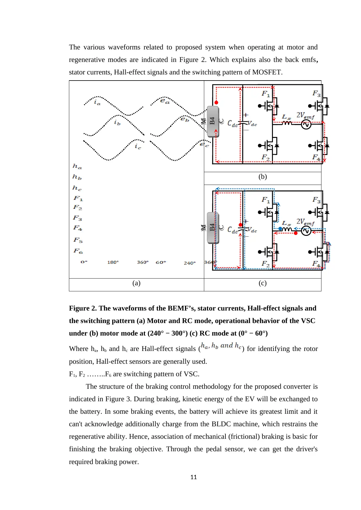
The various waveforms related to proposed system when operating at motor and
regenerative modes are indicated in Figure 2. Which explains also the back emfs,
stator currents, Hall-effect signals and the switching pattern of MOSFET.
(b)
(a) (c)
Figure 2. The waveforms of the BEMF’s, stator currents, Hall-effect signals and
the switching pattern (a) Motor and RC mode, operational behavior of the VSC
under (b) motor mode at (240° − 300°) (c) RC mode at (0° − 60°)
Where ha, hb and hc are Hall-effect signals ( ) for identifying the rotor
position, Hall-effect sensors are generally used.
F1, F2 ……..F6 are switching pattern of VSC.
The structure of the braking control methodology for the proposed converter is
indicated in Figure 3. During braking, kinetic energy of the EV will be exchanged to
the battery. In some braking events, the battery will achieve its greatest limit and it
can't acknowledge additionally charge from the BLDC machine, which restrains the
regenerative ability. Hence, association of mechanical (frictional) braking is basic for
finishing the braking objective. Through the pedal sensor, we can get the driver's
required braking power.
11
M
B4
C
M
B4
C
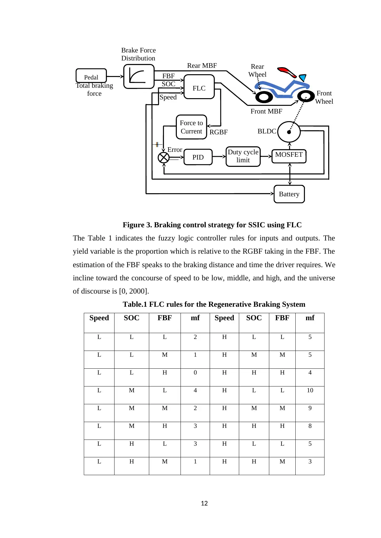
Figure 3. Braking control strategy for SSIC using FLC
The Table 1 indicates the fuzzy logic controller rules for inputs and outputs. The
yield variable is the proportion which is relative to the RGBF taking in the FBF. The
estimation of the FBF speaks to the braking distance and time the driver requires. We
incline toward the concourse of speed to be low, middle, and high, and the universe
of discourse is [0, 2000].
Table.1 FLC rules for the Regenerative Braking System
Speed SOC FBF mf Speed SOC FBF mf
L L L 2 H L L 5
L L M 1 H M M 5
L L H 0 H H H 4
L M L 4 H L L 10
L M M 2 H M M 9
L M H 3 H H H 8
L H L 3 H L L 5
L H M 1 H H M 3
12
BLDC
Front
Wheel
Error
RGBF
Brake Force
Distribution
Speed
SOC
FBFPedal
FLC
Force to
Current
PID Duty cycle
limit
Battery
MOSFET
Rear MBF
Front MBF
Total braking
force
Rear
Wheel
⊘ This is a preview!⊘
Do you want full access?
Subscribe today to unlock all pages.
Trusted by 1+ million students worldwide
1 out of 21
Related Documents


Your All-in-One AI-Powered Toolkit for Academic Success.
+13062052269
info@desklib.com
Available 24*7 on WhatsApp / Email
![[object Object]](/_next/static/media/star-bottom.7253800d.svg)
Unlock your academic potential
Copyright © 2020–2026 A2Z Services. All Rights Reserved. Developed and managed by ZUCOL.