Analysis and Life Assessment of High-Temperature Header Piping System
VerifiedAdded on 2023/01/07
|10
|2201
|75
Report
AI Summary
This report provides a comprehensive life assessment of high-temperature header piping and tube systems, crucial components in power plants. It begins with an introduction to the topic, followed by a literature review exploring creep and fatigue phenomena, key factors affecting the lifespan of these systems. The report then details various methods used, including the application of codes like ASME B31.1 and EN12952, and the significance of material and geometry. A quantitative analysis is presented, focusing on calculating creep stress, remaining life analysis, and fatigue damage. The report concludes with a discussion of the findings and recommendations for improving the efficiency and longevity of the piping systems, emphasizing the importance of proper equipment and protective measures. The document includes relevant formulas and equations to support the analysis and provides references to related publications.

Life assessment of high-temperature header piping and tube system
Paraphrase This Document
Need a fresh take? Get an instant paraphrase of this document with our AI Paraphraser
Table of Contents
2.1 INTRODUCTION.....................................................................................................................1
2.2 Literature review........................................................................................................................1
2.4 Quantitative analysis..................................................................................................................3
2.5 Discussion..................................................................................................................................6
CONCLUSION................................................................................................................................6
REFERENCES................................................................................................................................7

⊘ This is a preview!⊘
Do you want full access?
Subscribe today to unlock all pages.
Trusted by 1+ million students worldwide
2.1 INTRODUCTION
There are different technology and techniques are used for maintaining and operating the
competitiveness of the pressure of ageing in power plant. The tube system ageing in the power
plant is using high temperature that is heading through the piping (Narayanan, Rezaei, K. &
Nackenhorst, 2016). The pressure in the temperature is high that is up to 1000 degree F that is
majorly considering on the different task of operation. This report will needs to various methods
which is used to super header heaters which is consider by the dry systems. In this report there
are two types of designing pressures will be seen that is ASME B31.1 as well as EN12952 that
will be used to installing the remaining creep. In this various types of tubing system and piping
will be conducted with the support of tube and header.
2.2 Literature review
Creep
It is very crucial to study and determine different aspects of the creep in order to gain
better understanding. Creep is a completely common phenomenon in steam headers and pipes of
the steam turbines. Steam headers refer as the pipes which deliver the steam generated within
side the boiler to the turbine or power generation unit. These steam headers, as a result of being
subjected to very high temperatures are recognized to revel in creep. With creep, elements
deform and in the end damage due to very small stresses. The study of creep is significant for
analysing the suitability of progressing the usage of boiler components (Hao, 2016). Creep can
be describe as the study which is conducted with the support of computer simulation as well as
plugging stress values, time along with this temperature into the life formulas of the creeps
which is provided by the standards of EN12952 and ASME B31.1. Therefore this formulas and
way of doing task is not very correct and effective the prediction.
Fatigue
Another components which happens in steam conveying segments of power plants is
fatigue which can be consider as the result of the patterns of activity that they are gotten through.
The patterns of an evaporator activity are consistent state-shut down-fire up-consistent state.
Because of this reality, boiler parts are exposed to weariness stresses. Computing or calculation
of the fatigue life of boiler segment from their cycle length and worry at most extreme limit is
significant to the structure of power plants
1
Paraphrase This Document
Need a fresh take? Get an instant paraphrase of this document with our AI Paraphraser
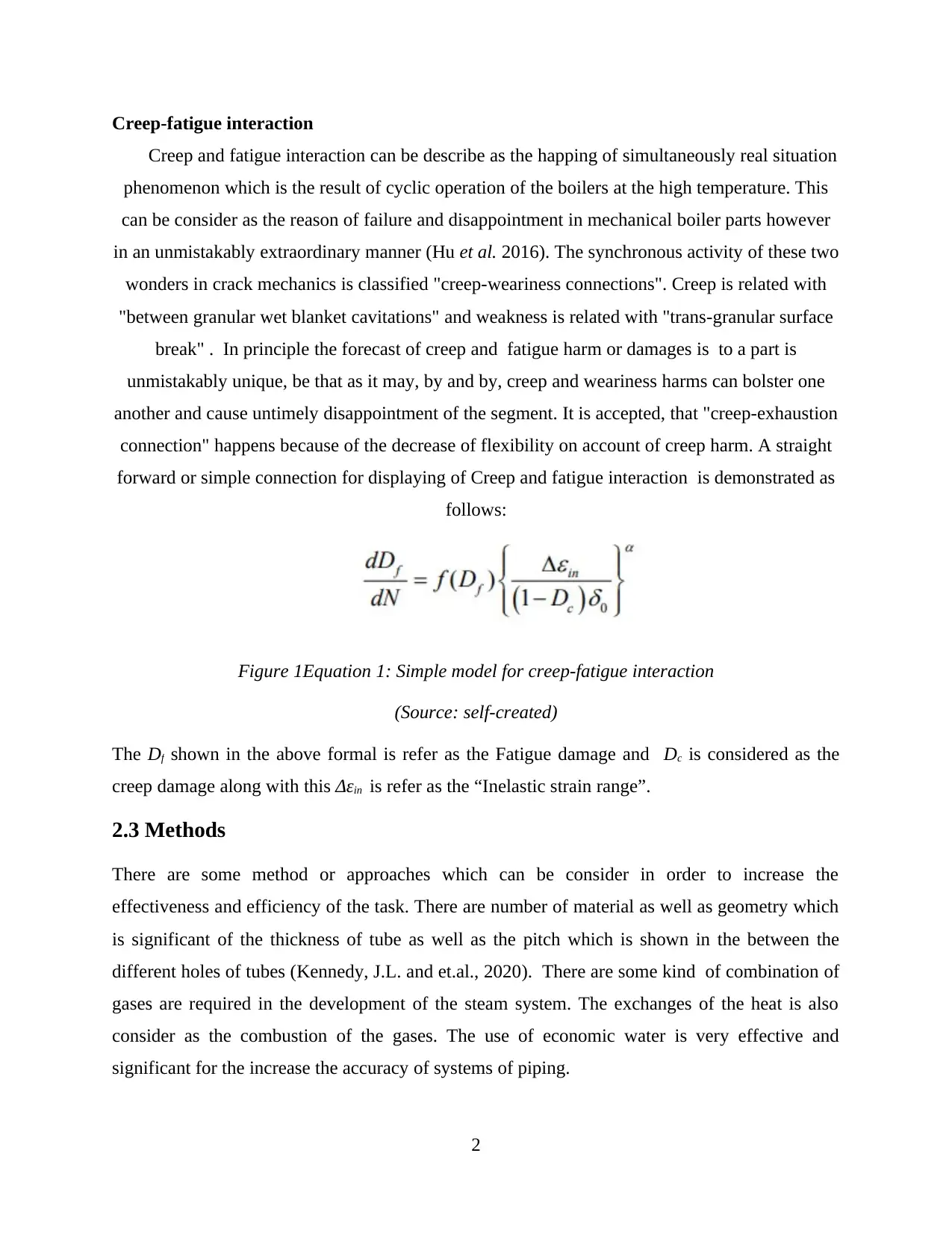
Creep-fatigue interaction
Creep and fatigue interaction can be describe as the happing of simultaneously real situation
phenomenon which is the result of cyclic operation of the boilers at the high temperature. This
can be consider as the reason of failure and disappointment in mechanical boiler parts however
in an unmistakably extraordinary manner (Hu et al. 2016). The synchronous activity of these two
wonders in crack mechanics is classified "creep-weariness connections". Creep is related with
"between granular wet blanket cavitations" and weakness is related with "trans-granular surface
break" . In principle the forecast of creep and fatigue harm or damages is to a part is
unmistakably unique, be that as it may, by and by, creep and weariness harms can bolster one
another and cause untimely disappointment of the segment. It is accepted, that "creep-exhaustion
connection" happens because of the decrease of flexibility on account of creep harm. A straight
forward or simple connection for displaying of Creep and fatigue interaction is demonstrated as
follows:
Figure 1Equation 1: Simple model for creep-fatigue interaction
(Source: self-created)
The Df shown in the above formal is refer as the Fatigue damage and Dc is considered as the
creep damage along with this Δεin is refer as the “Inelastic strain range”.
2.3 Methods
There are some method or approaches which can be consider in order to increase the
effectiveness and efficiency of the task. There are number of material as well as geometry which
is significant of the thickness of tube as well as the pitch which is shown in the between the
different holes of tubes (Kennedy, J.L. and et.al., 2020). There are some kind of combination of
gases are required in the development of the steam system. The exchanges of the heat is also
consider as the combustion of the gases. The use of economic water is very effective and
significant for the increase the accuracy of systems of piping.
2
There are a few kinds of stream drms are likewise being utilized that can go about as repositories
in which age of the cylinder is to be required. In the super heaters outlets broiler is the primary
and major element which is required. The temperature values in the pipe channel warmers are
almost around 565-degree centigrade. The all out in administration of the Time is to be required
in which 82000 hrs of work are principally used to begin the warming frameworks. The drum
inside the stream is situated in the pipelines warmers. This may close all the valves that are
related with the two kinds of structuring frameworks that are utilized. Air vents are being
introduced in the funnel warmers wherein EN12952 and ASMEB31.1these two sorts of codes are
being utilized. The inward fitting is done inside the system of piping that can evacuate all the
dampness and make the channels to produce all the stream drums. The 56 header thickness is
being related with the different system of piping in which tube frameworks are being required. In
the Super heaters, there are two sorts of headers that are utilized that can isolate all the
procedures with the controllers (Koka and Mathew, 2018). The components that are appended to
the Super heaters are Clamp and GWR designs that can control all the kinds of radiators issues.
The huge drums for the most part serve different kinds of assortments in which base blow down
is being required. The super heaters can be manufactures in the set time with the wall tubes is
being utilized as well as installed in the correct parallels.
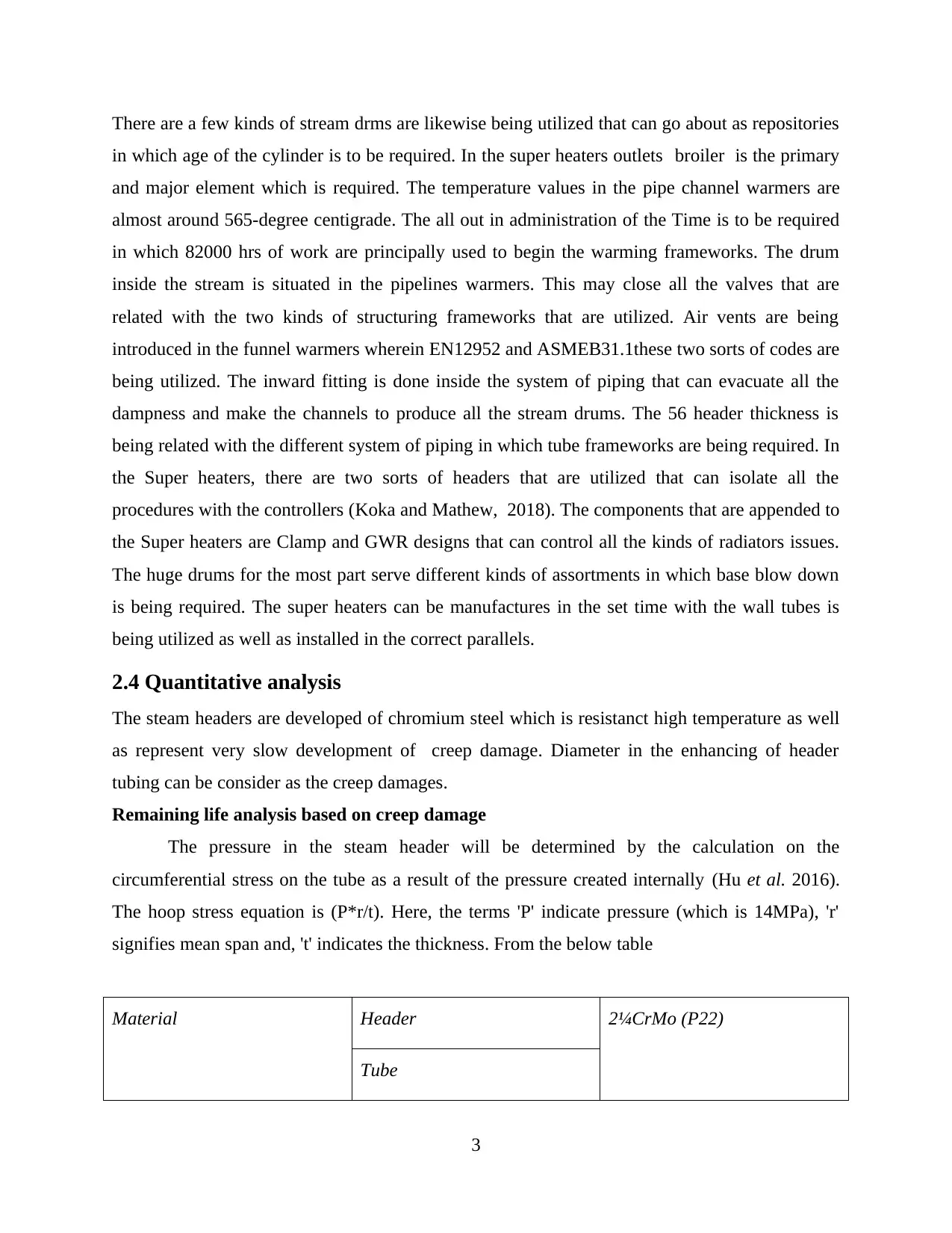
2.4 Quantitative analysis
The steam headers are developed of chromium steel which is resistanct high temperature as well
as represent very slow development of creep damage. Diameter in the enhancing of header
tubing can be consider as the creep damages.
Remaining life analysis based on creep damage
The pressure in the steam header will be determined by the calculation on the
circumferential stress on the tube as a result of the pressure created internally (Hu et al. 2016).
The hoop stress equation is (P*r/t). Here, the terms 'P' indicate pressure (which is 14MPa), 'r'
signifies mean span and, 't' indicates the thickness. From the below table
Material Header 2¼CrMo (P22)
Tube
3
in which age of the cylinder is to be required. In the super heaters outlets broiler is the primary
and major element which is required. The temperature values in the pipe channel warmers are
almost around 565-degree centigrade. The all out in administration of the Time is to be required
in which 82000 hrs of work are principally used to begin the warming frameworks. The drum
inside the stream is situated in the pipelines warmers. This may close all the valves that are
related with the two kinds of structuring frameworks that are utilized. Air vents are being
introduced in the funnel warmers wherein EN12952 and ASMEB31.1these two sorts of codes are
being utilized. The inward fitting is done inside the system of piping that can evacuate all the
dampness and make the channels to produce all the stream drums. The 56 header thickness is
being related with the different system of piping in which tube frameworks are being required. In
the Super heaters, there are two sorts of headers that are utilized that can isolate all the
procedures with the controllers (Koka and Mathew, 2018). The components that are appended to
the Super heaters are Clamp and GWR designs that can control all the kinds of radiators issues.
The huge drums for the most part serve different kinds of assortments in which base blow down
is being required. The super heaters can be manufactures in the set time with the wall tubes is
being utilized as well as installed in the correct parallels.
2.4 Quantitative analysis
The steam headers are developed of chromium steel which is resistanct high temperature as well
as represent very slow development of creep damage. Diameter in the enhancing of header
tubing can be consider as the creep damages.
Remaining life analysis based on creep damage
The pressure in the steam header will be determined by the calculation on the
circumferential stress on the tube as a result of the pressure created internally (Hu et al. 2016).
The hoop stress equation is (P*r/t). Here, the terms 'P' indicate pressure (which is 14MPa), 'r'
signifies mean span and, 't' indicates the thickness. From the below table
Material Header 2¼CrMo (P22)
Tube
3
⊘ This is a preview!⊘
Do you want full access?
Subscribe today to unlock all pages.
Trusted by 1+ million students worldwide
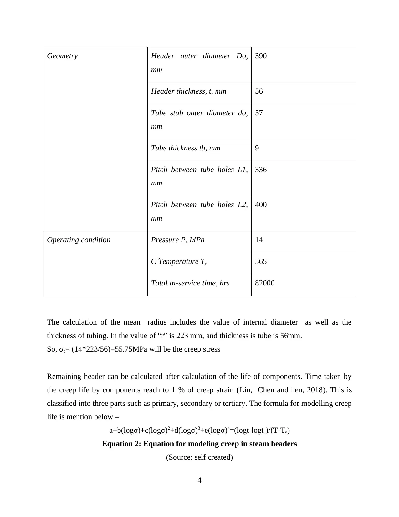
Geometry Header outer diameter Do,
mm
390
Header thickness, t, mm 56
Tube stub outer diameter do,
mm
57
Tube thickness tb, mm 9
Pitch between tube holes L1,
mm
336
Pitch between tube holes L2,
mm
400
Operating condition Pressure P, MPa 14
C
Temperature T, 565
Total in-service time, hrs 82000
The calculation of the mean radius includes the value of internal diameter as well as the
thickness of tubing. In the value of “r” is 223 mm, and thickness is tube is 56mm.
So, σc= (14*223/56)=55.75MPa will be the creep stress
Remaining header can be calculated after calculation of the life of components. Time taken by
the creep life by components reach to 1 % of creep strain (Liu, Chen and hen, 2018). This is
classified into three parts such as primary, secondary or tertiary. The formula for modelling creep
life is mention below –
a+b(logσ)+c(logσ)2+d(logσ)3+e(logσ)4=(logt-logta)/(T-Ta)
Equation 2: Equation for modeling creep in steam headers
(Source: self created)
4
mm
390
Header thickness, t, mm 56
Tube stub outer diameter do,
mm
57
Tube thickness tb, mm 9
Pitch between tube holes L1,
mm
336
Pitch between tube holes L2,
mm
400
Operating condition Pressure P, MPa 14
C
Temperature T, 565
Total in-service time, hrs 82000
The calculation of the mean radius includes the value of internal diameter as well as the
thickness of tubing. In the value of “r” is 223 mm, and thickness is tube is 56mm.
So, σc= (14*223/56)=55.75MPa will be the creep stress
Remaining header can be calculated after calculation of the life of components. Time taken by
the creep life by components reach to 1 % of creep strain (Liu, Chen and hen, 2018). This is
classified into three parts such as primary, secondary or tertiary. The formula for modelling creep
life is mention below –
a+b(logσ)+c(logσ)2+d(logσ)3+e(logσ)4=(logt-logta)/(T-Ta)
Equation 2: Equation for modeling creep in steam headers
(Source: self created)
4
Paraphrase This Document
Need a fresh take? Get an instant paraphrase of this document with our AI Paraphraser
In the equation, the coefficients of the logσ term in the creep life modeling equation. Value of
constant a = -1.38, b = 2.83, c = -2.2, d = 0.75 and e = -0.1.
T is operating temperature and value of T = (565 + 273)K = 838K. Whereas Ta = 610 and logta =
4.61. The time to failure can be calculated from the equation and is around 108 hours and ideally
it would not remain function for more than 1.5*105 hours. Through this it is estimated that
approx 0.7*105 hours of service life is still left.
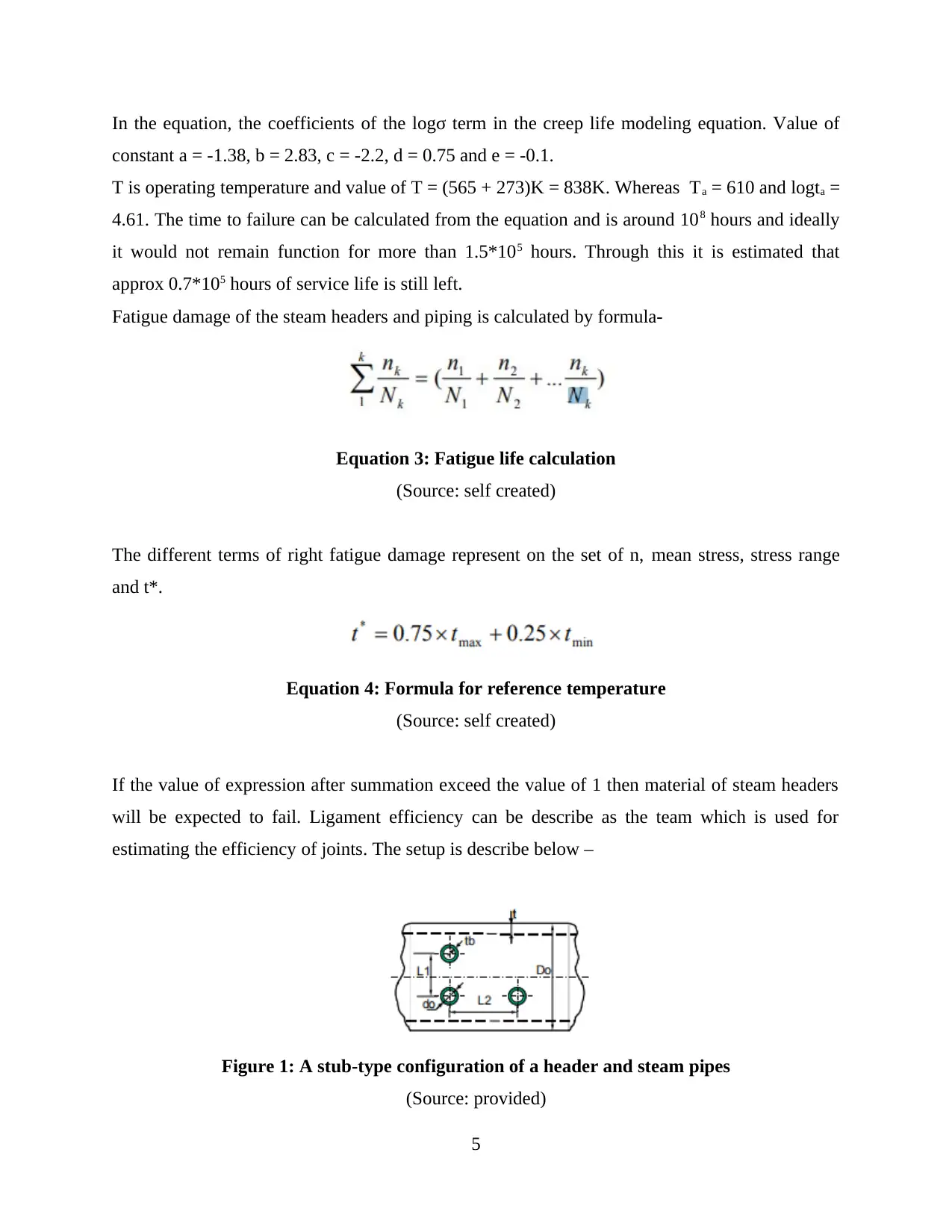
Fatigue damage of the steam headers and piping is calculated by formula-
Equation 3: Fatigue life calculation
(Source: self created)
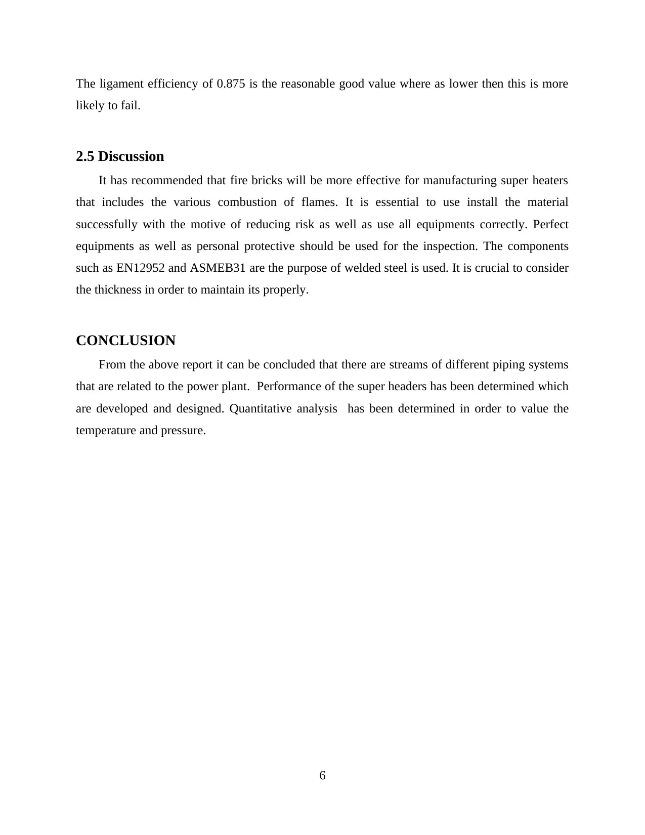
The different terms of right fatigue damage represent on the set of n, mean stress, stress range
and t*.
Equation 4: Formula for reference temperature
(Source: self created)
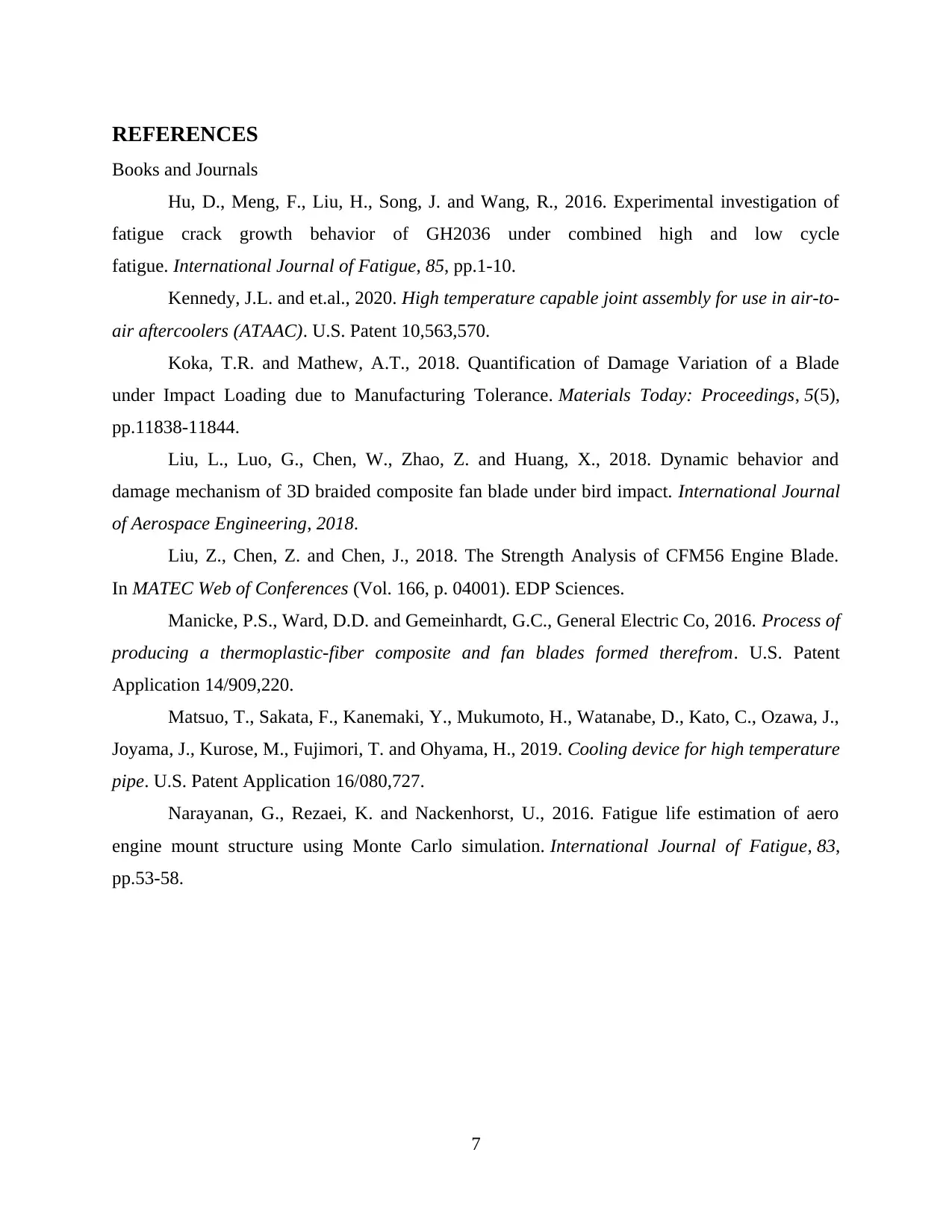
If the value of expression after summation exceed the value of 1 then material of steam headers
will be expected to fail. Ligament efficiency can be describe as the team which is used for
estimating the efficiency of joints. The setup is describe below –
Figure 1: A stub-type configuration of a header and steam pipes
(Source: provided)
5
constant a = -1.38, b = 2.83, c = -2.2, d = 0.75 and e = -0.1.
T is operating temperature and value of T = (565 + 273)K = 838K. Whereas Ta = 610 and logta =
4.61. The time to failure can be calculated from the equation and is around 108 hours and ideally
it would not remain function for more than 1.5*105 hours. Through this it is estimated that
approx 0.7*105 hours of service life is still left.
Fatigue damage of the steam headers and piping is calculated by formula-
Equation 3: Fatigue life calculation
(Source: self created)
The different terms of right fatigue damage represent on the set of n, mean stress, stress range
and t*.
Equation 4: Formula for reference temperature
(Source: self created)
If the value of expression after summation exceed the value of 1 then material of steam headers
will be expected to fail. Ligament efficiency can be describe as the team which is used for
estimating the efficiency of joints. The setup is describe below –
Figure 1: A stub-type configuration of a header and steam pipes
(Source: provided)
5
The ligament efficiency of 0.875 is the reasonable good value where as lower then this is more
likely to fail.
2.5 Discussion
It has recommended that fire bricks will be more effective for manufacturing super heaters
that includes the various combustion of flames. It is essential to use install the material
successfully with the motive of reducing risk as well as use all equipments correctly. Perfect
equipments as well as personal protective should be used for the inspection. The components
such as EN12952 and ASMEB31 are the purpose of welded steel is used. It is crucial to consider
the thickness in order to maintain its properly.
CONCLUSION
From the above report it can be concluded that there are streams of different piping systems
that are related to the power plant. Performance of the super headers has been determined which
are developed and designed. Quantitative analysis has been determined in order to value the
temperature and pressure.
6
⊘ This is a preview!⊘
Do you want full access?
Subscribe today to unlock all pages.
Trusted by 1+ million students worldwide
REFERENCES
Books and Journals
Hu, D., Meng, F., Liu, H., Song, J. and Wang, R., 2016. Experimental investigation of
fatigue crack growth behavior of GH2036 under combined high and low cycle
fatigue. International Journal of Fatigue, 85, pp.1-10.
Kennedy, J.L. and et.al., 2020. High temperature capable joint assembly for use in air-to-
air aftercoolers (ATAAC). U.S. Patent 10,563,570.
Koka, T.R. and Mathew, A.T., 2018. Quantification of Damage Variation of a Blade
under Impact Loading due to Manufacturing Tolerance. Materials Today: Proceedings, 5(5),
pp.11838-11844.
Liu, L., Luo, G., Chen, W., Zhao, Z. and Huang, X., 2018. Dynamic behavior and
damage mechanism of 3D braided composite fan blade under bird impact. International Journal
of Aerospace Engineering, 2018.
Liu, Z., Chen, Z. and Chen, J., 2018. The Strength Analysis of CFM56 Engine Blade.
In MATEC Web of Conferences (Vol. 166, p. 04001). EDP Sciences.
Manicke, P.S., Ward, D.D. and Gemeinhardt, G.C., General Electric Co, 2016. Process of
producing a thermoplastic-fiber composite and fan blades formed therefrom. U.S. Patent
Application 14/909,220.
Matsuo, T., Sakata, F., Kanemaki, Y., Mukumoto, H., Watanabe, D., Kato, C., Ozawa, J.,
Joyama, J., Kurose, M., Fujimori, T. and Ohyama, H., 2019. Cooling device for high temperature
pipe. U.S. Patent Application 16/080,727.
Narayanan, G., Rezaei, K. and Nackenhorst, U., 2016. Fatigue life estimation of aero
engine mount structure using Monte Carlo simulation. International Journal of Fatigue, 83,
pp.53-58.
7
1 out of 10
Related Documents


Your All-in-One AI-Powered Toolkit for Academic Success.
+13062052269
info@desklib.com
Available 24*7 on WhatsApp / Email
![[object Object]](/_next/static/media/star-bottom.7253800d.svg)
Unlock your academic potential
Copyright © 2020–2026 A2Z Services. All Rights Reserved. Developed and managed by ZUCOL.