Project: Design of RTD Temperature Measurement System
VerifiedAdded on 2021/02/19
|16
|2518
|166
Project
AI Summary
This project report details the design and construction of a temperature measurement system utilizing a platinum Resistance Temperature Detector (RTD) sensor. The report begins with an introduction outlining the study background, real-life applications of temperature sensors, and the project's aims and objectives, which include designing a system to measure temperatures between 0 and 100 degrees Celsius. The project delves into the theory and design, explaining RTD sensors, their classes, modes of operation, and different types, with a focus on PT100 sensors. The design and construction phase involves the use of a bridge circuit, resistance values, power dissipation calculations, and operational amplifiers. The report further discusses the results, including the use of an operational amplifier as a voltage follower and the considerations when integrating RTDs within a bridge circuit. The project concludes with recommendations for enhancing accuracy, and reflections on design strengths and weaknesses, particularly the impact of wire length and self-heating effects on accuracy. The project emphasizes the practical application of temperature sensors and the importance of amplification in achieving accurate measurements.

Project
Paraphrase This Document
Need a fresh take? Get an instant paraphrase of this document with our AI Paraphraser

Table of Contents
CHAPTER 1: INTRODUCTION....................................................................................................1
Study background........................................................................................................................1
Real life applications....................................................................................................................1
Aims and objectives.....................................................................................................................1
CHAPTER 2: THEORY AND DESIGN.........................................................................................1
RTD Sensor..................................................................................................................................2
Class of sensor.............................................................................................................................3
Mode of RTD operation ..............................................................................................................3
Types of sensor............................................................................................................................4
CHAPTER 3: DESIGN AND CONSTRUCTION .........................................................................6
Introduction..................................................................................................................................6
Bridge circuit...............................................................................................................................6
Resistance values ........................................................................................................................6
Power dissipation ........................................................................................................................6
Operational amplifier ..................................................................................................................6
System linearity ..........................................................................................................................6
CHAPTER 4: DISCUSSION AND RESULTS ..............................................................................6
CHAPTER 5: RECOMMENDATIONS AND CONCLUSION ....................................................7
Reflection.....................................................................................................................................7
Design strength and weakness.....................................................................................................7
Recommendations........................................................................................................................7
REFERENCES................................................................................................................................9
APPENDIX....................................................................................................................................10
CHAPTER 1: INTRODUCTION
Study background
Temperature sensor is defined as the device which measures the heat energy or coldness
for sensing temperature variations and to product an equivalent digital or analogue output. It is
very critical to develop temperature controller and measurement systems which are not
influenced by the environmental stress. For maintaining the desired temperature it is essential
that suitable sensors are chosen for the designing process. There has been trade off between
various types of sensors. For instance from cost effectiveness and suitability of wide application
range thermocouples are better. However, from the accuracy context resistance temperature
detector (RTD) are considered as the best. Thus, it is required that temperature sensors chosen
for the temperature measurement must be selected appropriately.
Real life applications
The temperature measurement sensors and devices are used in various practical
applications. For the qualitative production of the manufactured goods it is important for the
manufacturers to maintain a constant temperature so that safe and accurate production can be
carried out (Dorf, 2016). Such manufacturing plants and process essentially employ temperature
measurement sensors so that temperature changes can be identified and constant temperature can
be sustained. Thus, these systems are used in medical devices, food processing industries,
automotive processes and chemical handling.
Aims and objectives
The aim of this report is to design a temperature measurement system which uses
temperature sensors to measure the temperature. The key objectives of the project are as follows:
To use platinum RTD based sensor for designing temperature measurement system which
can measure temperature in the range 0-100 degree Celsius.
To design bridge circuit and to measure current value and different performance factors
of sensor.
To use and justify a suitable amplifier for the designed system.
CHAPTER 2: THEORY AND DESIGN
Temperature sensors are broadly classified as the contact and non contact sensors. The
contact sensors needs physical contact with the surface for monitoring the temperature changes.
On the other hand non-contact temperature employs the radiation or convection for sensing the
1
⊘ This is a preview!⊘
Do you want full access?
Subscribe today to unlock all pages.
Trusted by 1+ million students worldwide
changes. The most common types of temperature sensors are RTD, thermocouple and
thermistors. The thermocouple consist of two different metallic wires which forms a junction or
connection at two points. The temperature difference between these two points reflects the
temperature changes in proportionality. Contrary to this in this study RTD sensors are used
which uses temperature and resistance correlation for the temperature measurement.
RTD Sensor
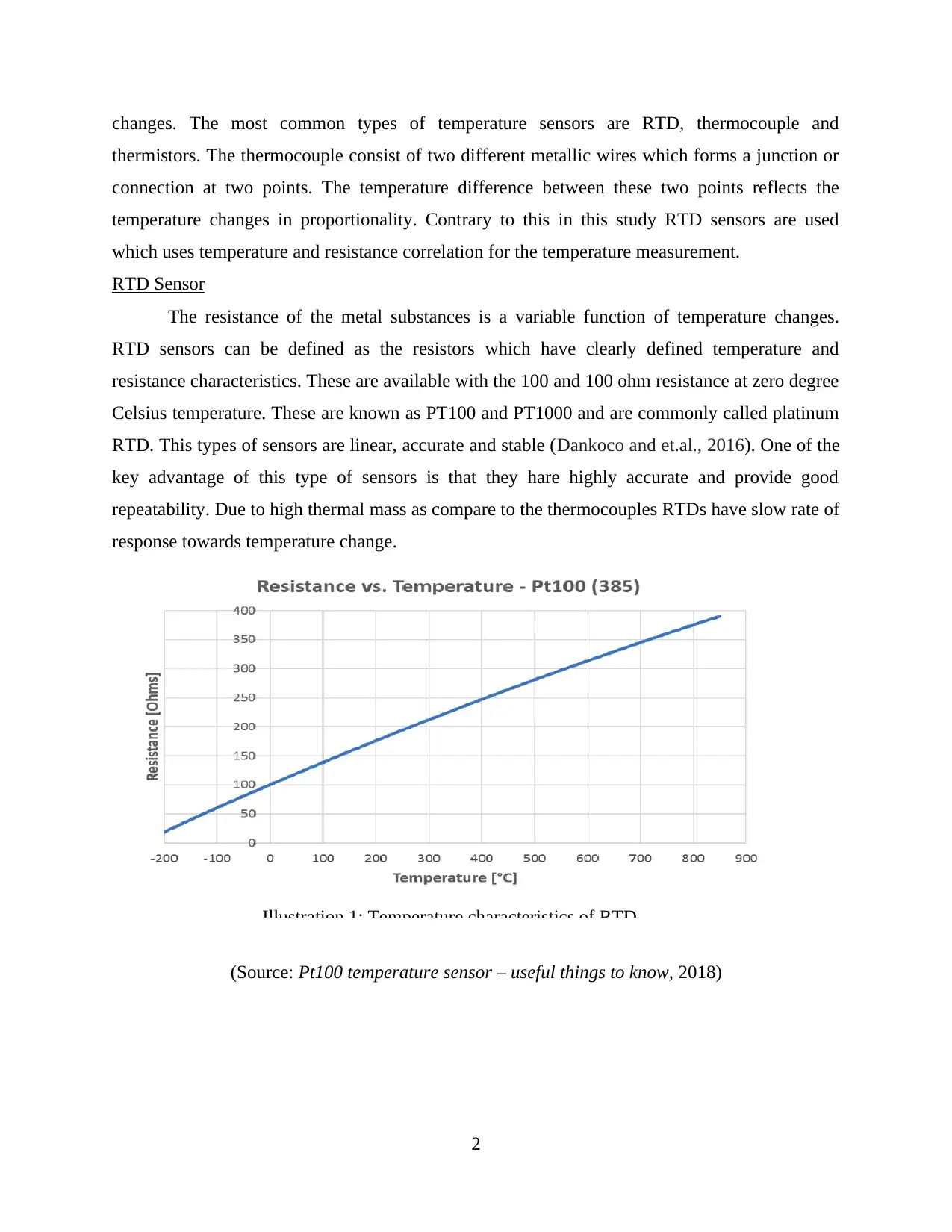
The resistance of the metal substances is a variable function of temperature changes.
RTD sensors can be defined as the resistors which have clearly defined temperature and
resistance characteristics. These are available with the 100 and 100 ohm resistance at zero degree
Celsius temperature. These are known as PT100 and PT1000 and are commonly called platinum
RTD. This types of sensors are linear, accurate and stable (Dankoco and et.al., 2016). One of the
key advantage of this type of sensors is that they hare highly accurate and provide good
repeatability. Due to high thermal mass as compare to the thermocouples RTDs have slow rate of
response towards temperature change.
(Source: Pt100 temperature sensor – useful things to know, 2018)
2
Illustration 1: Temperature characteristics of RTD
thermistors. The thermocouple consist of two different metallic wires which forms a junction or
connection at two points. The temperature difference between these two points reflects the
temperature changes in proportionality. Contrary to this in this study RTD sensors are used
which uses temperature and resistance correlation for the temperature measurement.
RTD Sensor
The resistance of the metal substances is a variable function of temperature changes.
RTD sensors can be defined as the resistors which have clearly defined temperature and
resistance characteristics. These are available with the 100 and 100 ohm resistance at zero degree
Celsius temperature. These are known as PT100 and PT1000 and are commonly called platinum
RTD. This types of sensors are linear, accurate and stable (Dankoco and et.al., 2016). One of the
key advantage of this type of sensors is that they hare highly accurate and provide good
repeatability. Due to high thermal mass as compare to the thermocouples RTDs have slow rate of
response towards temperature change.
(Source: Pt100 temperature sensor – useful things to know, 2018)
2
Illustration 1: Temperature characteristics of RTD
Paraphrase This Document
Need a fresh take? Get an instant paraphrase of this document with our AI Paraphraser
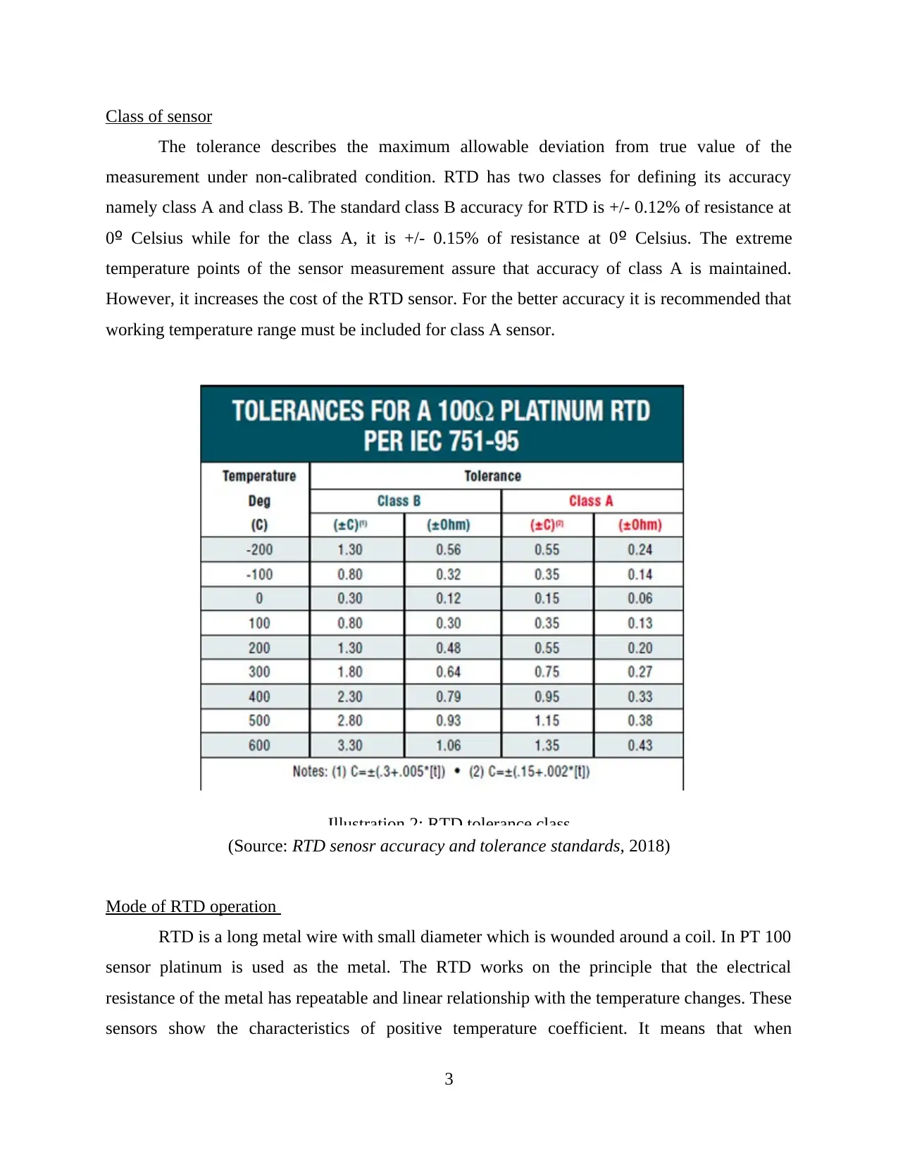
Class of sensor
The tolerance describes the maximum allowable deviation from true value of the
measurement under non-calibrated condition. RTD has two classes for defining its accuracy
namely class A and class B. The standard class B accuracy for RTD is +/- 0.12% of resistance at
0º Celsius while for the class A, it is +/- 0.15% of resistance at 0º Celsius. The extreme
temperature points of the sensor measurement assure that accuracy of class A is maintained.
However, it increases the cost of the RTD sensor. For the better accuracy it is recommended that
working temperature range must be included for class A sensor.
(Source: RTD senosr accuracy and tolerance standards, 2018)
Mode of RTD operation
RTD is a long metal wire with small diameter which is wounded around a coil. In PT 100
sensor platinum is used as the metal. The RTD works on the principle that the electrical
resistance of the metal has repeatable and linear relationship with the temperature changes. These
sensors show the characteristics of positive temperature coefficient. It means that when
3
Illustration 2: RTD tolerance class
temperature is increased the value of electric resistance is also increased. At base temperature the
resistance of the metal is directly proportional to the wire length and indirectly proportional to
the cross sectional area of wire. The electrical circuit consisting of RTD calculate the resistance
change and then this calculated change is used to measure the required reading of temperature
variations.
The RTD sensors converts the temperature changes into voltage by calculating the
resistance of the metal used. The pure metals or some specific alloys which shows the positive
temperature coefficient are the best suitable for the construction of RTD. Mostly platinum,
copper and BALCO wires are used in the sensor. These metals are capable to withstand high
temperatures as well as have high resistance coefficient (Quant and et.al. 2018). As compare to
platinum copper or nickel are less expensive but since they can operate at low temperature range
they are not preferred for the design. RTD sensors are known as the passive resistive devices.
Thus output voltage can be obtained by providing constant current which increases with the
temperature linearly. The operating range of the RTD is 100 ohms at 0 degree Celsius and
operates in the range -200 to +600 degree Celsius. However due to self heating effects of the
wire original reading may vary which must be corrected. For this purpose the sensor is connected
with Wheatstone bridge. The bridge connections provide additional wires so that leads can be
compensated.
Types of sensor
RTD sensors are available in three types of configuration namely two wired RTD, three
wired and four wired RTD. In the simplest two wire RTD resistor terminals are used for the
temperature measurement. Contrary to this in the 3 wire configuration along with the resistive
terminal an additional wire is also used. This extra wire provides the compensation technique for
the lead resistance from instrumentation to RTD. Thought the response rate of RTD for rapidly
varying temperature changes is low but for the industrial purpose it provides highly accurate
readings. In the 4 wire configuration two additional wires two resistance measures are essentially
calculated which are then used to eliminate the magnetic effects.
4
⊘ This is a preview!⊘
Do you want full access?
Subscribe today to unlock all pages.
Trusted by 1+ million students worldwide
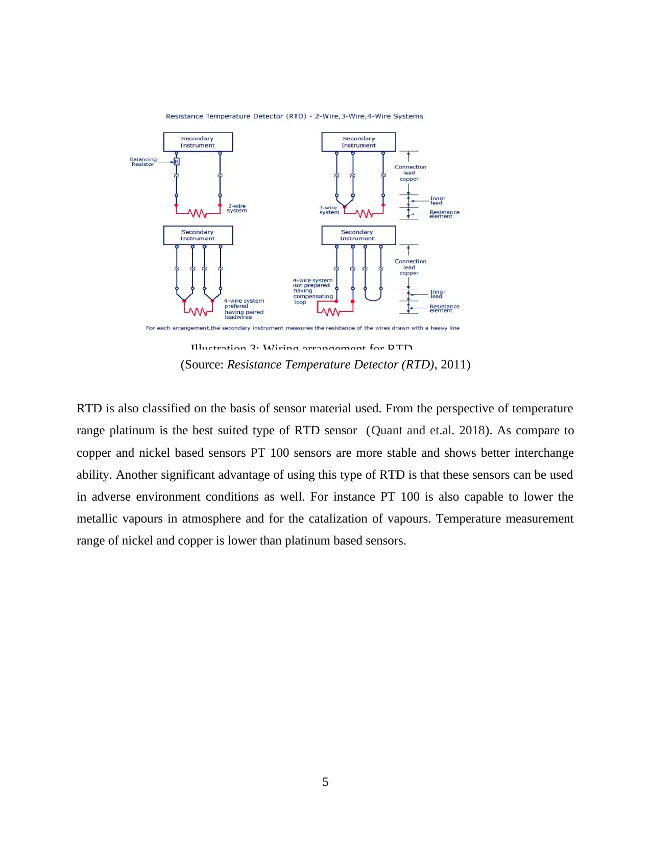
(Source: Resistance Temperature Detector (RTD), 2011)
RTD is also classified on the basis of sensor material used. From the perspective of temperature
range platinum is the best suited type of RTD sensor (Quant and et.al. 2018). As compare to
copper and nickel based sensors PT 100 sensors are more stable and shows better interchange
ability. Another significant advantage of using this type of RTD is that these sensors can be used
in adverse environment conditions as well. For instance PT 100 is also capable to lower the
metallic vapours in atmosphere and for the catalization of vapours. Temperature measurement
range of nickel and copper is lower than platinum based sensors.
5
Illustration 3: Wiring arrangement for RTD
Paraphrase This Document
Need a fresh take? Get an instant paraphrase of this document with our AI Paraphraser
(Source: Resistance Temperature Detector (RTD), 2011)
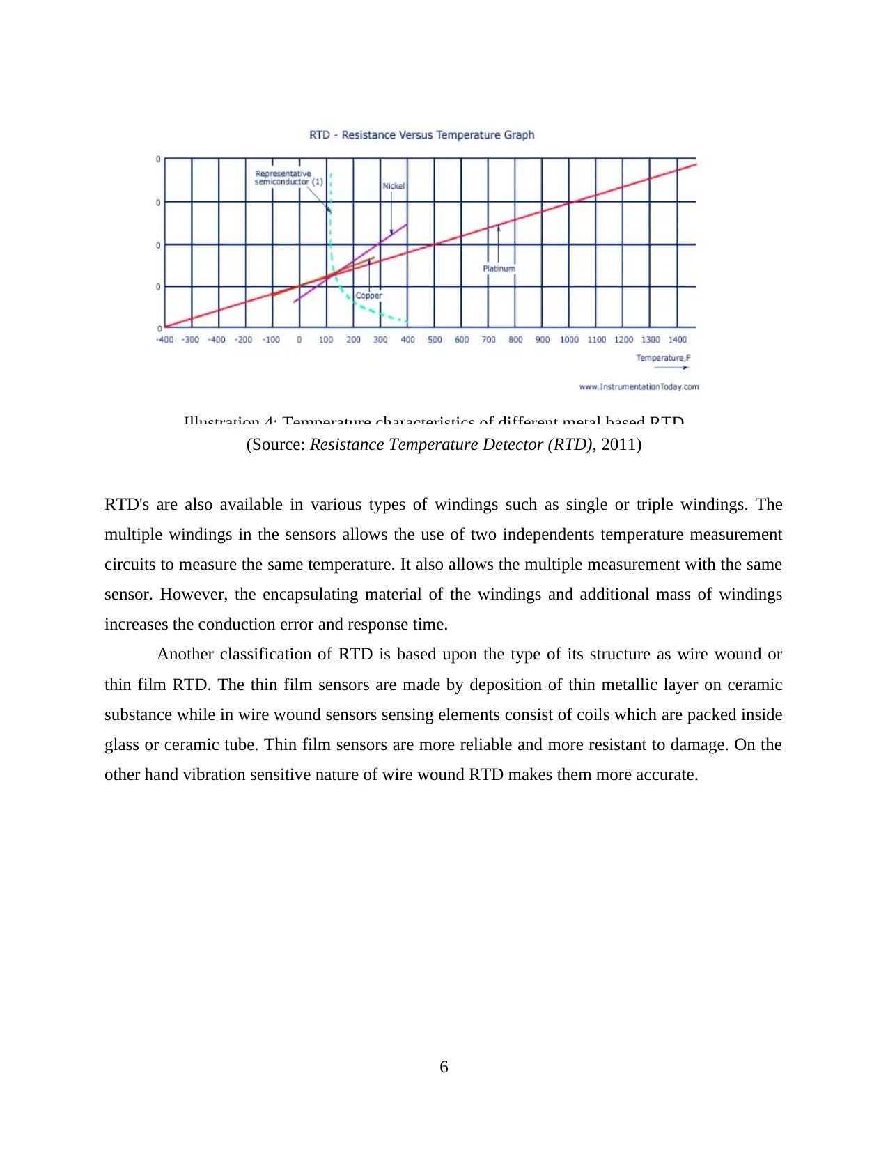
RTD's are also available in various types of windings such as single or triple windings. The
multiple windings in the sensors allows the use of two independents temperature measurement
circuits to measure the same temperature. It also allows the multiple measurement with the same
sensor. However, the encapsulating material of the windings and additional mass of windings
increases the conduction error and response time.
Another classification of RTD is based upon the type of its structure as wire wound or
thin film RTD. The thin film sensors are made by deposition of thin metallic layer on ceramic
substance while in wire wound sensors sensing elements consist of coils which are packed inside
glass or ceramic tube. Thin film sensors are more reliable and more resistant to damage. On the
other hand vibration sensitive nature of wire wound RTD makes them more accurate.
6
Illustration 4: Temperature characteristics of different metal based RTD
CHAPTER 3: DESIGN AND CONSTRUCTION
Introduction
Bridge circuit
Resistance values
Power dissipation
Operational amplifier
System linearity
CHAPTER 4: DISCUSSION AND RESULTS
For connecting fusion device with RTD voltage divider circuit is used in which reference
voltage output is used to drive the circuit. The design uses operational amplifier as voltage
follower so that adequate current can be supplied and reference voltage can be buffered. When
RTD is used in the bridge then, several aspects are taken into account. For instance for the
differential input amplifier fusion current monitoring is used. The RTD tolerance influences the
accuracy of voltage divider (Quant and et.al. 2018). It is required that a stable voltage reference
must be used so that accuracy can be enhanced. In the bridge when the value of R1 is small then
the divider circuit providers more linear output and linearity is improved as the result of
decreased dynamic range. It also lowers the value of excitation current. The amplifier used in the
circuit has constant gain equals to 10 and has unipolar nature. Since the device is also required to
be used in the remote area amplification is needed. In the design instrumentation amplifier is
chosen which has good common node rejection ratio. This type of amplifier is differential in
nature and is specifically designed for such type of applications. The low noise and quad low
power makes the amplifier suitable for the designed temperature measurement system. It has
been also analysed from that the RTD sensors can provide maximum resolution only when the
system is designed with the lowest resistance value. For obtaining the maximum value of slope
the value of R2 is set to zero. Though sensor resistor cannot be controlled but for the optimum
value of slope R3 can be chosen. The output voltage of the sensor resistance changes linearly
only when value of R3 is much higher than that of R2 (Cui and et.al., 2018). The worst case
equivalent series circuit of the bridge helps to obtain the power requirements of the bridge. It has
been also evaluated that the bridge output does not vary linearly with the resistance changes in
RTD. For correction of this bridge non-linearity temperature must be sweep with known
increments and the resultant values are recorded for the calibration.
7
⊘ This is a preview!⊘
Do you want full access?
Subscribe today to unlock all pages.
Trusted by 1+ million students worldwide
CHAPTER 5: RECOMMENDATIONS AND CONCLUSION
Reflection
The project has been very knowledgable for me as it gave me an opportunity to apply my
knowledge of temperature sensors into practical designing process. Through the bridge circuit
and then amplification I learned that how amplification process can influence the actual
measurements. The construction and calculative phase also helped me to gain the knowledge of
different metal characteristics and the designing attributes of RTD.
Design strength and weakness
One of the key benefit of using PT 100 sensors is that the platinum wire based
temperature sensor is highly stable over time and provides linear response. However one of
weakness of this design is that for providing nominal value of 100 ohm resistance wire length is
shortened. Thus, with the low resistance values sensor lead wire resistance and self heating can
affect the accuracy of measured temperature. A minor change in resistance also requires
amplification so that signal level can be increased.
Recommendations
For the accurate design it is recommended that for maximum flexibility in the
temperature measurements fusion device must be used. The use of fusion voltage with RTD can
enhance the measurement resolution and range. It has been also analysed that for the improved
accuracy of the designed system an instrumentation amplifier must be used with RTD bridge for
0.5 C resolution. In order to provide the suitable noise rejection RTD interface must be
improved. This can be done by providing buffering to fusion voltage reference so that source
current limitations can be avoided.
8
Paraphrase This Document
Need a fresh take? Get an instant paraphrase of this document with our AI Paraphraser
REFERENCES
Books and Journals
Dorf, R.C., 2016. Sensors, Nanoscience, Biomedical Engineering, and Instruments: Sensors
Nanoscience Biomedical Engineering. CRC press.
Dankoco, M.D., Tesfay, G.Y., Bènevent, E. and Bendahan, M., 2016. Temperature sensor
realized by inkjet printing process on flexible substrate. Materials Science and
Engineering: B, 205, pp.1-5.
Cui, X., Chen, J., Zhu, Y. and Jiang, W., 2018. Lightweight and conductive carbon
black/chlorinated poly (propylene carbonate) foams with a remarkable negative
temperature coefficient effect of resistance for temperature sensor applications. Journal
of Materials Chemistry C, 6(35), pp.9354-9362.
Quant, F.R., Agarwal, J. and Iyer, S., TSI Inc, 2018. Air and gas flow velocity and temperature
sensor probe. U.S. Patent Application 15/551,152.
Online
Resistance Temperature Detector (RTD). 2011. [Online]. Accessed through
<http://www.instrumentationtoday.com/resistance-temperature-detector-rtd/2011/09/>
Pt100 temperature sensor – useful things to know. 2018. [Online]. Accessed through
<https://blog.beamex.com/pt100-temperature-sensor>
RTD senosr accuracy and tolerance standards. 2018. [Online]. Accessed through
<https://www.thermometricscorp.com/acstan.html>
Temperature sensors. 2019. [Online]. Accessed through
<https://www.engineersgarage.com/articles/temperature-sensors>
9
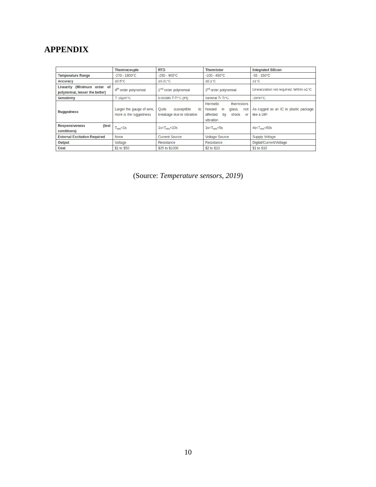
APPENDIX
(Source: Temperature sensors, 2019)
10
(Source: Temperature sensors, 2019)
10
⊘ This is a preview!⊘
Do you want full access?
Subscribe today to unlock all pages.
Trusted by 1+ million students worldwide
1 out of 16
Related Documents


Your All-in-One AI-Powered Toolkit for Academic Success.
+13062052269
info@desklib.com
Available 24*7 on WhatsApp / Email
![[object Object]](/_next/static/media/star-bottom.7253800d.svg)
Unlock your academic potential
Copyright © 2020–2026 A2Z Services. All Rights Reserved. Developed and managed by ZUCOL.