PLC Based Control Systems in Oil Refinery: Process Control Report
VerifiedAdded on 2023/06/14
|14
|2837
|106
Report
AI Summary
This report discusses the application of Programmable Logic Controllers (PLCs) in oil refinery control and automation. It highlights the importance of PLC software quality in production efficiency and addresses the gap between academic research and industrial practices in PLC programming. The report details the use of PLC systems in conjunction with SCADA for monitoring and controlling oil refinery processes. It also presents three GUI units designed for crude oil storage, distillation, and product storage, explaining the functionalities and components of each unit, including valves, tanks, pumps, transmitters, and metering stations. The report emphasizes the role of PLC systems in reducing human errors and improving overall refinery operations.
Running head: PLC BASED CONTROL SYSTEMS USED IN OIL REFINERY CONTROL
PLC BASED CONTROL SYSTEMS USED IN OIL REFINERY CONTROL
[Author Name(s), First M. Last, Omit Titles and Degrees]
[Institutional Affiliation(s)]
PLC BASED CONTROL SYSTEMS USED IN OIL REFINERY CONTROL
[Author Name(s), First M. Last, Omit Titles and Degrees]
[Institutional Affiliation(s)]
Paraphrase This Document
Need a fresh take? Get an instant paraphrase of this document with our AI Paraphraser
2
PLC BASED CONTROL SYSTEMS USED IN OIL REFINERY CONTROL
Programmable Logic Controllers based control system used in oil refinery control
Introduction
Programmable Logic Controllers (PLCs) are computers that are specifically designed and
applied in the industry for the purposes of controlling and automation of the processes and the
machinery used in the industry. Languages defined and specified in the International
Electrotechnical Commission 61131-3 standards are the only languages used in the programming
of Programmable Logic Controllers. The efficiency of production is directly influenced by the
quality of the Programmable Logic Controller software that is used in its control and automation.
An example can be observed in the case where a PLC software sequences an equipment in a way
that was not intended and as per designed by the designer or equipment that are interlocked may
remain in a state of wait for longer time than expected but the software will still manage to
successfully produce products of the required quality in as much as time and energy will be
wasted in the process of production.
Applications of Programmable Logic Controllers
As vast as the field of software engineering, a lot of research has been made that has seen
numerous publications made on the application of various theories and concepts to the PLC
software among them Petri nets and discrete event theory systems. Unfortunately, the impact of
the research, publications, and application did is negligible on the practice of PLC programming
as such findings have been found to be too sophisticated and challenging to be applied by most
of the PLC programmers (Shenoi, 2015). Further work has been done to establish the
applications of the principles of software engineering to the development of PLC software.
Among such work include recognition of the design patterns through the use of an object-
3
PLC BASED CONTROL SYSTEMS USED IN OIL REFINERY CONTROL
oriented approach as well as proposals on new high-level languages for the graphics. Despite a
positive remark on the development, it is worth noting that the research of literature on such term
as PLC software framework, PLC software architecture and scalable PLC software have not
yielded any significant results (Badir, 2016). Instead, the search results obtained are found to be
too complex and sophisticated to be applied in real life situation. This leaves a wide gap between
academic and scholarly publications and industrial application and practice of Programmable
Logic Controllers software.
It is not surprising that Programmable Logic Controllers are gaining more and more
sophistication with time and the trend expected to increase. To most of the vendors, the term
Programmable Automatic Controllers is being used as a form of degradation to the previous
generations of Programmable Logic Controllers an instead make the current generation look
more superior. In the ancient times, programming of the Programmable Logic Controllers was
done by people who have very little or absolutely no background knowledge of computer
programming (Furtado, 2013). This is contrary to the contemporary situation in which
programming is conducted by experts in computer programming, having an elaborate and
extensive understanding of the structures of data, the principles of object-oriented programming
among other skills and experience. These experts are opportunistic of the capabilities that are
provided by the latest Programmable Logic Controllers.
Contrary to most of the other types of software, Programmable Logic Controllers are seen and
used as a troubleshooting tool by the end user. The troubleshooting individual, who is in most
cases the electro-mechanical technician, has a limited range of skills in programming as they
have numerous other responsibilities to deliver (Colombo, 2014). This is one of the fundamental
points that is given priority during the development of Programmable Logic Controllers
⊘ This is a preview!⊘
Do you want full access?
Subscribe today to unlock all pages.
Trusted by 1+ million students worldwide
4
PLC BASED CONTROL SYSTEMS USED IN OIL REFINERY CONTROL
programs. A program is rated to be simple when it is easy to troubleshoot as compared to more
sophisticated ones. A production line which is easiest to troubleshoot normally has the highest
time up and hence perceived to be more profitable and efficient.
The oil refinery industry is one of the most important industries and sectors in the economy of
any country following the range of valuable products that it produces. A lot of studies have been
done with regards to the application of PLC systems in the operation of the boilers, treatment of
wastewater among other functionalities (McCormack, 2016). The operations of the boiler are
monitored through the use of controller PLC using communication cables which check the
pressure and temperature levels as well as the flow.
PLC system
In automating an oil refinery, it is important to develop a PLC system that checks in the plant
and aids in the reduction of the errors due to man. The PLC system is used to store instructions
internally that are used in the implementation of various functions among them sequencing,
timing, counting and arithmetic (Hathaway, 2014). These instructions control the different types
of machine processes through the use of either digital or analog output/input modules. PLC
systems are normally used in conjunction with SCADA systems which is a collection of
telemetry and data acquisition. This system collects data through the use of a Remote Terminal
Unit. The collected data is then carried by the PLC systems in conjunction with the Intelligent
Electronic Devices back to the central site to allow for the execution of the required analysis and
control after which the information is displayed on the operation screens (Badir, 2016). The most
important parts of the SCADA system include the Master Station, the PLC system and the
communication between the preceding components.
Paraphrase This Document
Need a fresh take? Get an instant paraphrase of this document with our AI Paraphraser
5
PLC BASED CONTROL SYSTEMS USED IN OIL REFINERY CONTROL
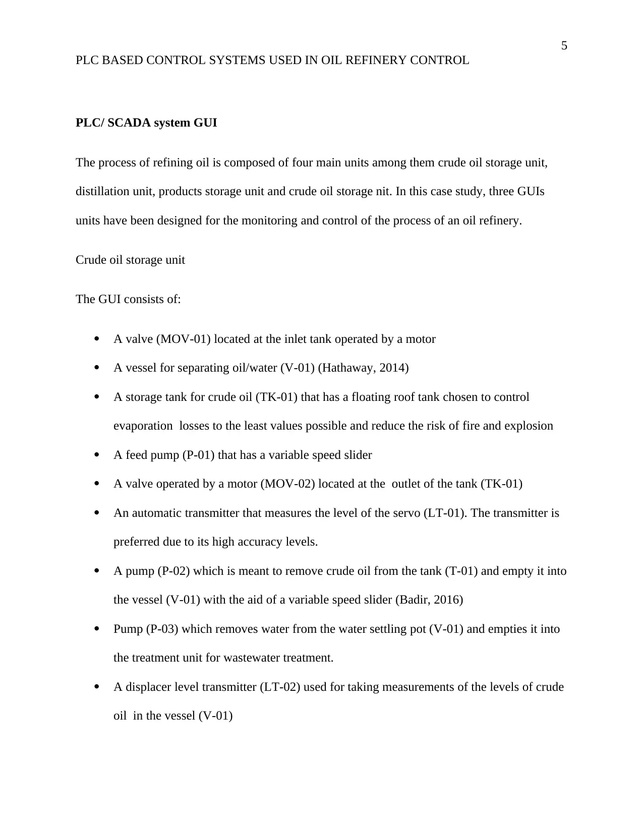
PLC/ SCADA system GUI
The process of refining oil is composed of four main units among them crude oil storage unit,
distillation unit, products storage unit and crude oil storage nit. In this case study, three GUIs
units have been designed for the monitoring and control of the process of an oil refinery.
Crude oil storage unit
The GUI consists of:
A valve (MOV-01) located at the inlet tank operated by a motor
A vessel for separating oil/water (V-01) (Hathaway, 2014)
A storage tank for crude oil (TK-01) that has a floating roof tank chosen to control
evaporation losses to the least values possible and reduce the risk of fire and explosion
A feed pump (P-01) that has a variable speed slider
A valve operated by a motor (MOV-02) located at the outlet of the tank (TK-01)
An automatic transmitter that measures the level of the servo (LT-01). The transmitter is
preferred due to its high accuracy levels.
A pump (P-02) which is meant to remove crude oil from the tank (T-01) and empty it into
the vessel (V-01) with the aid of a variable speed slider (Badir, 2016)
Pump (P-03) which removes water from the water settling pot (V-01) and empties it into
the treatment unit for wastewater treatment.
A displacer level transmitter (LT-02) used for taking measurements of the levels of crude
oil in the vessel (V-01)
PLC BASED CONTROL SYSTEMS USED IN OIL REFINERY CONTROL
PLC/ SCADA system GUI
The process of refining oil is composed of four main units among them crude oil storage unit,
distillation unit, products storage unit and crude oil storage nit. In this case study, three GUIs
units have been designed for the monitoring and control of the process of an oil refinery.
Crude oil storage unit
The GUI consists of:
A valve (MOV-01) located at the inlet tank operated by a motor
A vessel for separating oil/water (V-01) (Hathaway, 2014)
A storage tank for crude oil (TK-01) that has a floating roof tank chosen to control
evaporation losses to the least values possible and reduce the risk of fire and explosion
A feed pump (P-01) that has a variable speed slider
A valve operated by a motor (MOV-02) located at the outlet of the tank (TK-01)
An automatic transmitter that measures the level of the servo (LT-01). The transmitter is
preferred due to its high accuracy levels.
A pump (P-02) which is meant to remove crude oil from the tank (T-01) and empty it into
the vessel (V-01) with the aid of a variable speed slider (Badir, 2016)
Pump (P-03) which removes water from the water settling pot (V-01) and empties it into
the treatment unit for wastewater treatment.
A displacer level transmitter (LT-02) used for taking measurements of the levels of crude
oil in the vessel (V-01)
6
PLC BASED CONTROL SYSTEMS USED IN OIL REFINERY CONTROL
A displacer level transmitter (LDT-03) used for taking measurements of the levels of the
interface of water/crude oil in the water settling pot of (V-01) (Shenoi, 2015)
Transmitters of differential pressure flow rate (FT-01 and FT-02) having output signals of
between 4-20mA.
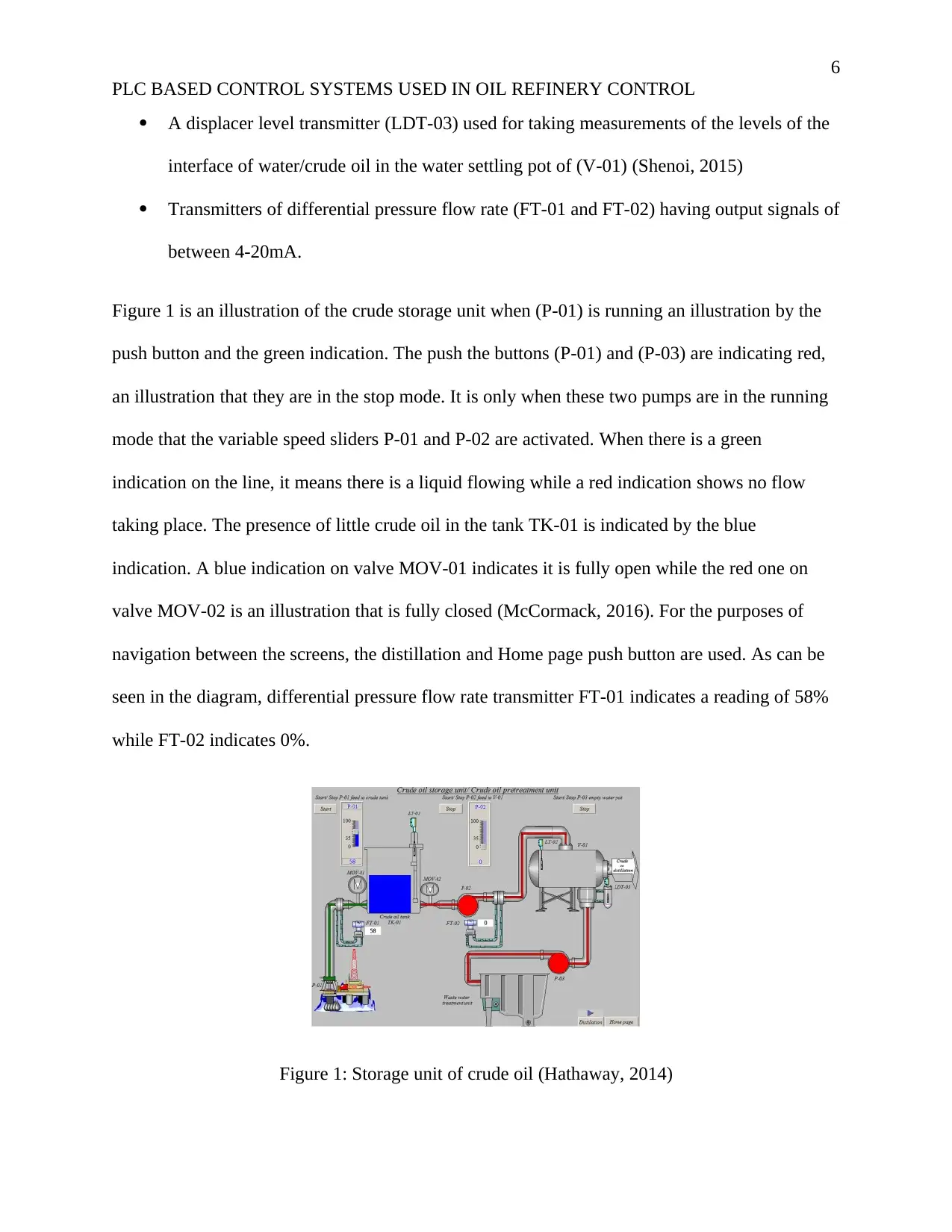
Figure 1 is an illustration of the crude storage unit when (P-01) is running an illustration by the
push button and the green indication. The push the buttons (P-01) and (P-03) are indicating red,
an illustration that they are in the stop mode. It is only when these two pumps are in the running
mode that the variable speed sliders P-01 and P-02 are activated. When there is a green
indication on the line, it means there is a liquid flowing while a red indication shows no flow
taking place. The presence of little crude oil in the tank TK-01 is indicated by the blue
indication. A blue indication on valve MOV-01 indicates it is fully open while the red one on
valve MOV-02 is an illustration that is fully closed (McCormack, 2016). For the purposes of
navigation between the screens, the distillation and Home page push button are used. As can be
seen in the diagram, differential pressure flow rate transmitter FT-01 indicates a reading of 58%
while FT-02 indicates 0%.
Figure 1: Storage unit of crude oil (Hathaway, 2014)
PLC BASED CONTROL SYSTEMS USED IN OIL REFINERY CONTROL
A displacer level transmitter (LDT-03) used for taking measurements of the levels of the
interface of water/crude oil in the water settling pot of (V-01) (Shenoi, 2015)
Transmitters of differential pressure flow rate (FT-01 and FT-02) having output signals of
between 4-20mA.
Figure 1 is an illustration of the crude storage unit when (P-01) is running an illustration by the
push button and the green indication. The push the buttons (P-01) and (P-03) are indicating red,
an illustration that they are in the stop mode. It is only when these two pumps are in the running
mode that the variable speed sliders P-01 and P-02 are activated. When there is a green
indication on the line, it means there is a liquid flowing while a red indication shows no flow
taking place. The presence of little crude oil in the tank TK-01 is indicated by the blue
indication. A blue indication on valve MOV-01 indicates it is fully open while the red one on
valve MOV-02 is an illustration that is fully closed (McCormack, 2016). For the purposes of
navigation between the screens, the distillation and Home page push button are used. As can be
seen in the diagram, differential pressure flow rate transmitter FT-01 indicates a reading of 58%
while FT-02 indicates 0%.
Figure 1: Storage unit of crude oil (Hathaway, 2014)
⊘ This is a preview!⊘
Do you want full access?
Subscribe today to unlock all pages.
Trusted by 1+ million students worldwide
7
PLC BASED CONTROL SYSTEMS USED IN OIL REFINERY CONTROL
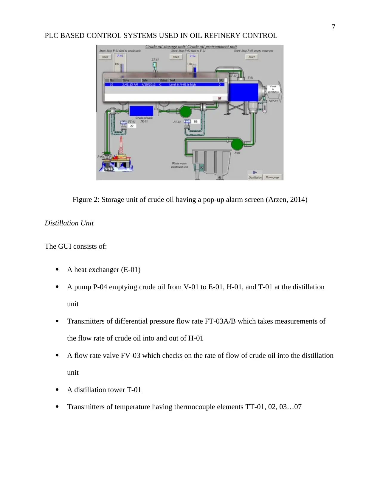
Figure 2: Storage unit of crude oil having a pop-up alarm screen (Arzen, 2014)
Distillation Unit
The GUI consists of:
A heat exchanger (E-01)
A pump P-04 emptying crude oil from V-01 to E-01, H-01, and T-01 at the distillation
unit
Transmitters of differential pressure flow rate FT-03A/B which takes measurements of
the flow rate of crude oil into and out of H-01
A flow rate valve FV-03 which checks on the rate of flow of crude oil into the distillation
unit
A distillation tower T-01
Transmitters of temperature having thermocouple elements TT-01, 02, 03…07
PLC BASED CONTROL SYSTEMS USED IN OIL REFINERY CONTROL
Figure 2: Storage unit of crude oil having a pop-up alarm screen (Arzen, 2014)
Distillation Unit
The GUI consists of:
A heat exchanger (E-01)
A pump P-04 emptying crude oil from V-01 to E-01, H-01, and T-01 at the distillation
unit
Transmitters of differential pressure flow rate FT-03A/B which takes measurements of
the flow rate of crude oil into and out of H-01
A flow rate valve FV-03 which checks on the rate of flow of crude oil into the distillation
unit
A distillation tower T-01
Transmitters of temperature having thermocouple elements TT-01, 02, 03…07
Paraphrase This Document
Need a fresh take? Get an instant paraphrase of this document with our AI Paraphraser
8
PLC BASED CONTROL SYSTEMS USED IN OIL REFINERY CONTROL
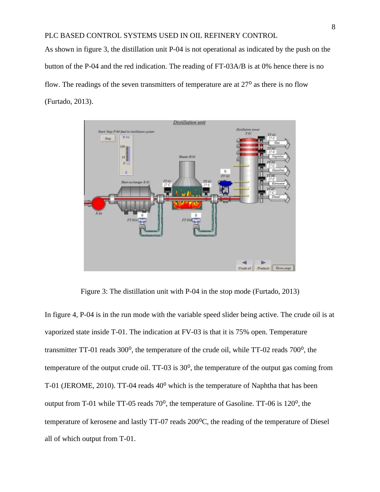
As shown in figure 3, the distillation unit P-04 is not operational as indicated by the push on the
button of the P-04 and the red indication. The reading of FT-03A/B is at 0% hence there is no
flow. The readings of the seven transmitters of temperature are at 27⁰ as there is no flow
(Furtado, 2013).
Figure 3: The distillation unit with P-04 in the stop mode (Furtado, 2013)
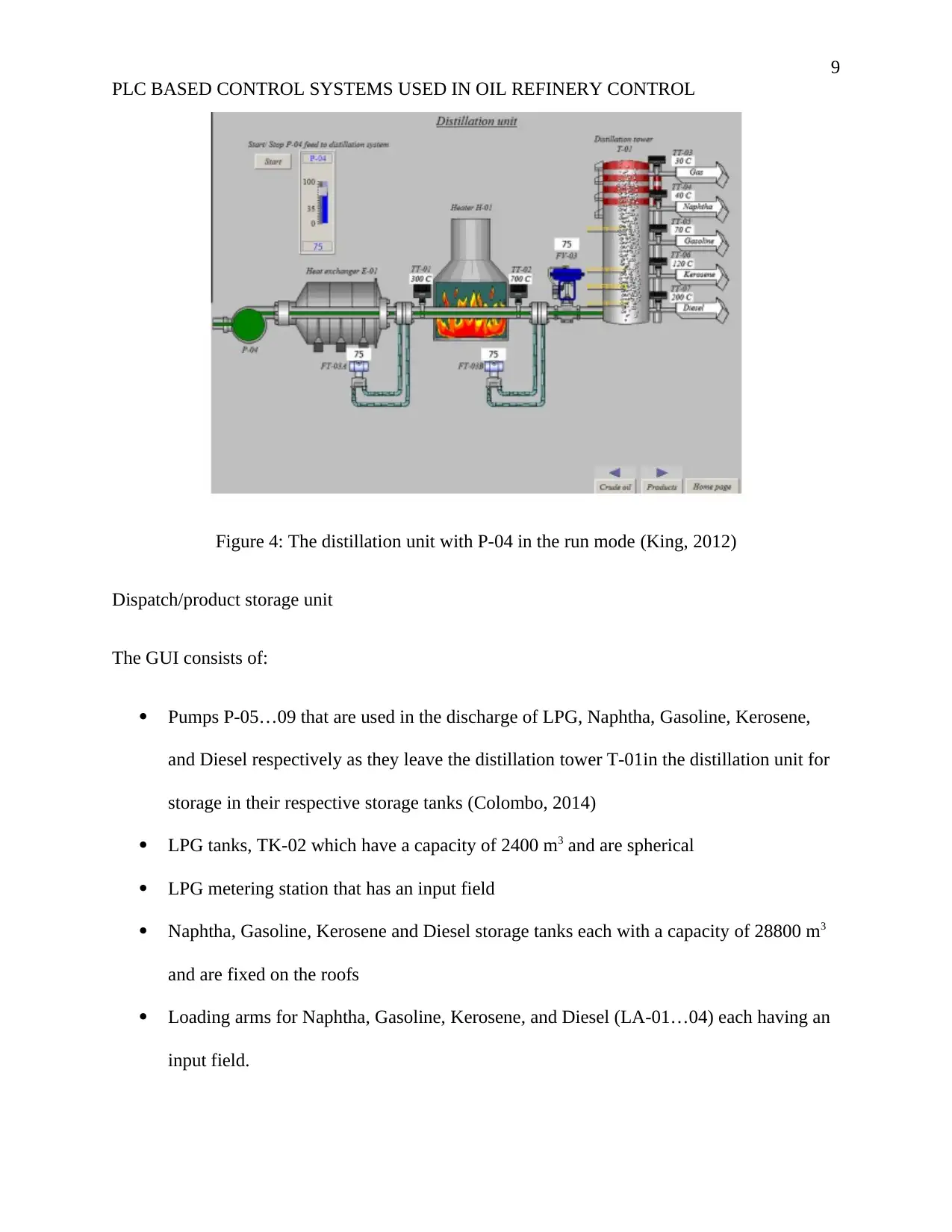
In figure 4, P-04 is in the run mode with the variable speed slider being active. The crude oil is at
vaporized state inside T-01. The indication at FV-03 is that it is 75% open. Temperature
transmitter TT-01 reads 300⁰, the temperature of the crude oil, while TT-02 reads 700⁰, the
temperature of the output crude oil. TT-03 is 30⁰, the temperature of the output gas coming from
T-01 (JEROME, 2010). TT-04 reads 40⁰ which is the temperature of Naphtha that has been
output from T-01 while TT-05 reads 70⁰, the temperature of Gasoline. TT-06 is 120⁰, the
temperature of kerosene and lastly TT-07 reads 200⁰C, the reading of the temperature of Diesel
all of which output from T-01.
PLC BASED CONTROL SYSTEMS USED IN OIL REFINERY CONTROL
As shown in figure 3, the distillation unit P-04 is not operational as indicated by the push on the
button of the P-04 and the red indication. The reading of FT-03A/B is at 0% hence there is no
flow. The readings of the seven transmitters of temperature are at 27⁰ as there is no flow
(Furtado, 2013).
Figure 3: The distillation unit with P-04 in the stop mode (Furtado, 2013)
In figure 4, P-04 is in the run mode with the variable speed slider being active. The crude oil is at
vaporized state inside T-01. The indication at FV-03 is that it is 75% open. Temperature
transmitter TT-01 reads 300⁰, the temperature of the crude oil, while TT-02 reads 700⁰, the
temperature of the output crude oil. TT-03 is 30⁰, the temperature of the output gas coming from
T-01 (JEROME, 2010). TT-04 reads 40⁰ which is the temperature of Naphtha that has been
output from T-01 while TT-05 reads 70⁰, the temperature of Gasoline. TT-06 is 120⁰, the
temperature of kerosene and lastly TT-07 reads 200⁰C, the reading of the temperature of Diesel
all of which output from T-01.
9
PLC BASED CONTROL SYSTEMS USED IN OIL REFINERY CONTROL
Figure 4: The distillation unit with P-04 in the run mode (King, 2012)
Dispatch/product storage unit
The GUI consists of:
Pumps P-05…09 that are used in the discharge of LPG, Naphtha, Gasoline, Kerosene,
and Diesel respectively as they leave the distillation tower T-01in the distillation unit for
storage in their respective storage tanks (Colombo, 2014)
LPG tanks, TK-02 which have a capacity of 2400 m3 and are spherical
LPG metering station that has an input field
Naphtha, Gasoline, Kerosene and Diesel storage tanks each with a capacity of 28800 m3
and are fixed on the roofs
Loading arms for Naphtha, Gasoline, Kerosene, and Diesel (LA-01…04) each having an
input field.
⊘ This is a preview!⊘
Do you want full access?
Subscribe today to unlock all pages.
Trusted by 1+ million students worldwide
10
PLC BASED CONTROL SYSTEMS USED IN OIL REFINERY CONTROL
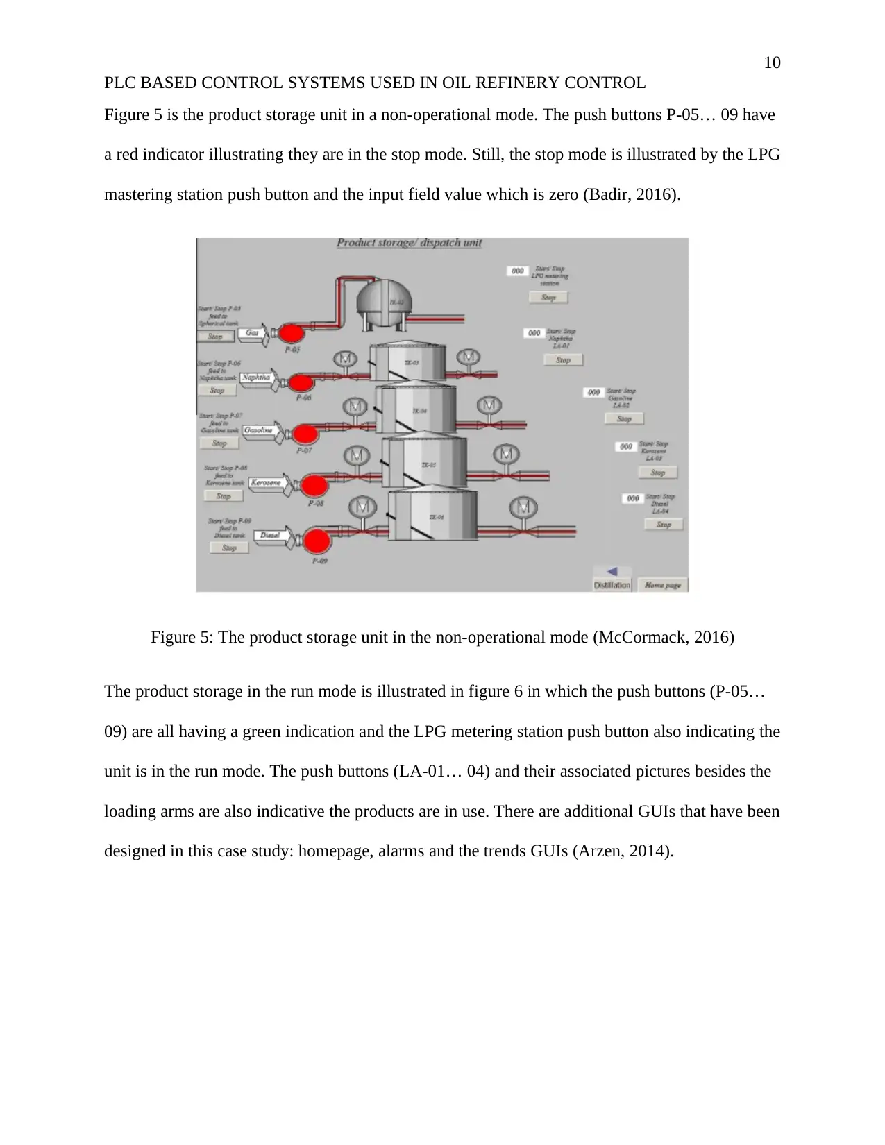
Figure 5 is the product storage unit in a non-operational mode. The push buttons P-05… 09 have
a red indicator illustrating they are in the stop mode. Still, the stop mode is illustrated by the LPG
mastering station push button and the input field value which is zero (Badir, 2016).
Figure 5: The product storage unit in the non-operational mode (McCormack, 2016)
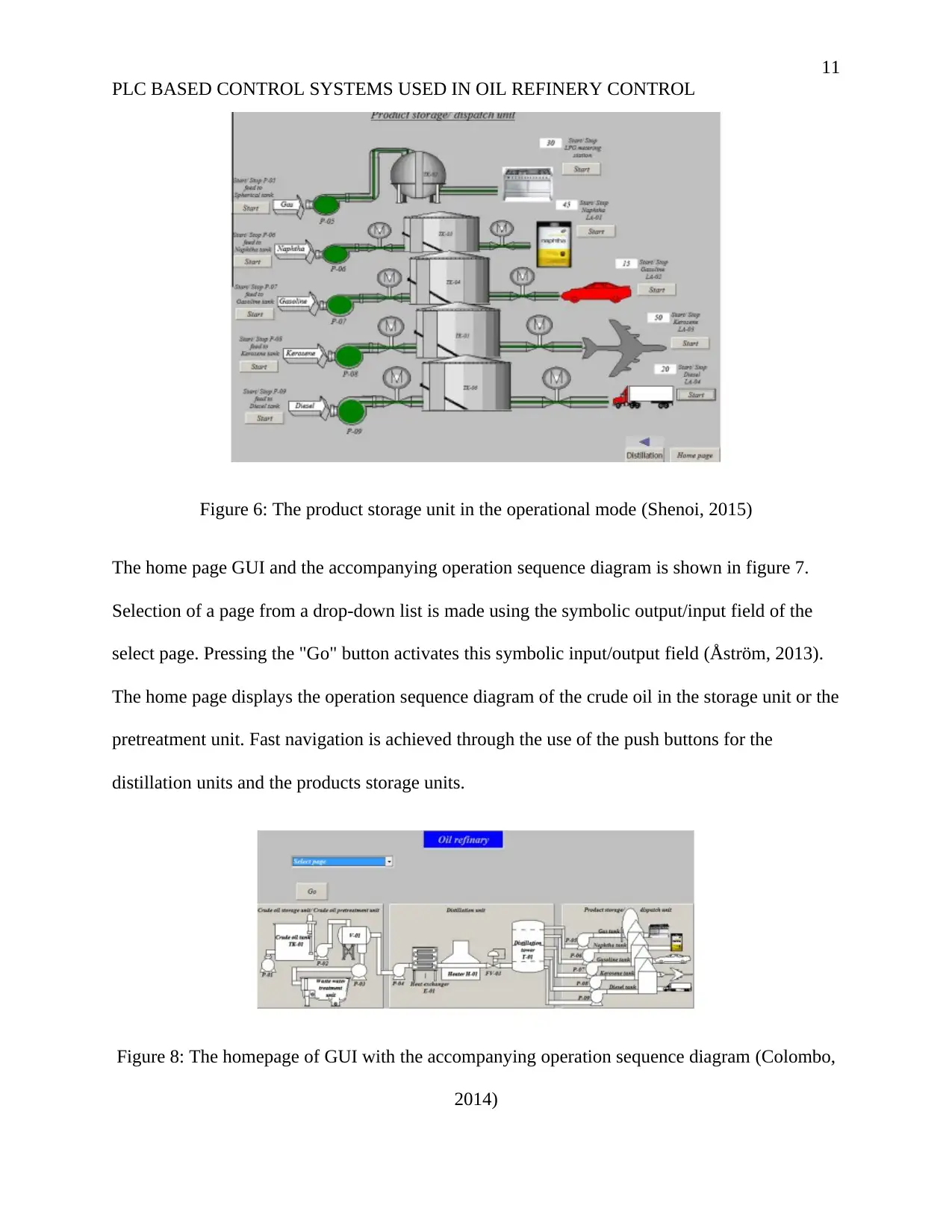
The product storage in the run mode is illustrated in figure 6 in which the push buttons (P-05…
09) are all having a green indication and the LPG metering station push button also indicating the
unit is in the run mode. The push buttons (LA-01… 04) and their associated pictures besides the
loading arms are also indicative the products are in use. There are additional GUIs that have been
designed in this case study: homepage, alarms and the trends GUIs (Arzen, 2014).
PLC BASED CONTROL SYSTEMS USED IN OIL REFINERY CONTROL
Figure 5 is the product storage unit in a non-operational mode. The push buttons P-05… 09 have
a red indicator illustrating they are in the stop mode. Still, the stop mode is illustrated by the LPG
mastering station push button and the input field value which is zero (Badir, 2016).
Figure 5: The product storage unit in the non-operational mode (McCormack, 2016)
The product storage in the run mode is illustrated in figure 6 in which the push buttons (P-05…
09) are all having a green indication and the LPG metering station push button also indicating the
unit is in the run mode. The push buttons (LA-01… 04) and their associated pictures besides the
loading arms are also indicative the products are in use. There are additional GUIs that have been
designed in this case study: homepage, alarms and the trends GUIs (Arzen, 2014).
Paraphrase This Document
Need a fresh take? Get an instant paraphrase of this document with our AI Paraphraser
11
PLC BASED CONTROL SYSTEMS USED IN OIL REFINERY CONTROL
Figure 6: The product storage unit in the operational mode (Shenoi, 2015)
The home page GUI and the accompanying operation sequence diagram is shown in figure 7.
Selection of a page from a drop-down list is made using the symbolic output/input field of the
select page. Pressing the "Go" button activates this symbolic input/output field (Åström, 2013).
The home page displays the operation sequence diagram of the crude oil in the storage unit or the
pretreatment unit. Fast navigation is achieved through the use of the push buttons for the
distillation units and the products storage units.
Figure 8: The homepage of GUI with the accompanying operation sequence diagram (Colombo,
2014)
12
PLC BASED CONTROL SYSTEMS USED IN OIL REFINERY CONTROL
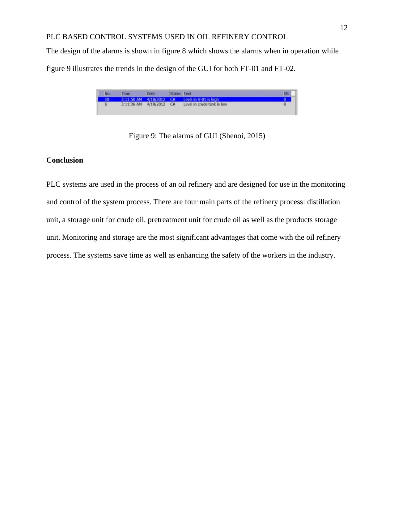
The design of the alarms is shown in figure 8 which shows the alarms when in operation while
figure 9 illustrates the trends in the design of the GUI for both FT-01 and FT-02.
Figure 9: The alarms of GUI (Shenoi, 2015)
Conclusion
PLC systems are used in the process of an oil refinery and are designed for use in the monitoring
and control of the system process. There are four main parts of the refinery process: distillation
unit, a storage unit for crude oil, pretreatment unit for crude oil as well as the products storage
unit. Monitoring and storage are the most significant advantages that come with the oil refinery
process. The systems save time as well as enhancing the safety of the workers in the industry.
PLC BASED CONTROL SYSTEMS USED IN OIL REFINERY CONTROL
The design of the alarms is shown in figure 8 which shows the alarms when in operation while
figure 9 illustrates the trends in the design of the GUI for both FT-01 and FT-02.
Figure 9: The alarms of GUI (Shenoi, 2015)
Conclusion
PLC systems are used in the process of an oil refinery and are designed for use in the monitoring
and control of the system process. There are four main parts of the refinery process: distillation
unit, a storage unit for crude oil, pretreatment unit for crude oil as well as the products storage
unit. Monitoring and storage are the most significant advantages that come with the oil refinery
process. The systems save time as well as enhancing the safety of the workers in the industry.
⊘ This is a preview!⊘
Do you want full access?
Subscribe today to unlock all pages.
Trusted by 1+ million students worldwide
1 out of 14
Related Documents


Your All-in-One AI-Powered Toolkit for Academic Success.
+13062052269
info@desklib.com
Available 24*7 on WhatsApp / Email
![[object Object]](/_next/static/media/star-bottom.7253800d.svg)
Unlock your academic potential
Copyright © 2020–2025 A2Z Services. All Rights Reserved. Developed and managed by ZUCOL.