Electrical Engineering Assignment: PLC Programming and Installation
VerifiedAdded on 2022/09/07
|14
|3573
|22
Practical Assignment
AI Summary
This assignment delves into the intricacies of Programmable Logic Controllers (PLCs) using the MicroLogix 1100 as a practical example. It begins by exploring the basic file types within a PLC, detailing the memory words consumed by each element and the type of data stored. The assignment then differentiates between integer and floating-point numbers, providing practical examples and conversion exercises. Furthermore, it examines the use of preset values for timers and counters, including maximum values. The assignment also covers the installation and configuration of a PLC in an industrial environment, highlighting crucial considerations such as environmental conditions, component distribution, and electrical power supply. It explores the differences between current and voltage signal transmission, offering examples of standard signal types and solutions to common issues. Additionally, the assignment addresses the concept of resolution in analogue signals and provides a calculation example for a digital-to-analogue converter. Finally, the assignment examines the installation of cables associated with analogue instruments, including precautions, and concludes with a detailed explanation and sketching of an instrumentation earthing system.
ELECTRONICS
Comparison of word and bit values
1. Using micrologic 1100 PLC as an example; list any five of the basic file types, and for
file type list the number of memory words each element consumes and describe type of
data stored in the file.
The micrologic 1100PLC contains 11 basic file types. They include;
Output- the file number is 0 and the element number is used to set I/O slot. In
addition, the word offset sets the words within the I/O slot.
Input- the file number is 1 and the element number is used to set I/O slot. In addition,
the word offset sets the words within the I/O slot.
Status- the file number is 2 and the element number is used to set the status word. In
addition, the word offset sets the words within the I/O slot and the bit offsets set the
bits within 0-15.
Bit- the file number is either 3 or sets the bit file to use bits between (3, 9-255). The
element sets the word and the bit offset is within 0-15 range.
Timer- the file number is either 4 or sets the timer file to use (4, 9-255). The element
number sets the timer index, the word offset sets the word offset within 0-2 range and
the bit offsets set the bits within 0-15.
2. The difference between integer and floating point numbers and practical examples for
each use.
An integer number is a set of data that is expressed as whole numbers and do not have any
fractions parts while floating point numbers are fixed specific number of bits that are arranged to
contain both whole number and fraction part. In short this means that integer data is presented in
decimal, octal or hexadecimal systems while floats are presented only in decimal number system.
Examples of integer include -125, 567, and 4,667 while examples of floating point numbers
include 1.2e34, and 0.98.
3. Express 1560.55 as a floating point number and as an integer.
Let’s convert 1560.55 to 32-bit floating point format
The integral part is 156010=110000110002.
The fractional part 0.55=0.100011001100110011012
Therefore, 1560.5510=11000011000 .100011001100110011012
Normalize 11000011000 .100011001100110011012
1
Paraphrase This Document
Need a fresh take? Get an instant paraphrase of this document with our AI Paraphraser
¿ 1.1000011000 100011001100110011012 × 210
The mantissa is 1000011000 10001100110011001101, the exponent is
10+127=137=100010012 the sign bit is 0
Therefore 1560.55is 010001001100001100010001100110011001101 in the format;
0 10001001 100001100010001100110011001101
¿ 226188 CCCD16
4. What type of number can only be used for the preset values of timers and counters and
what is the largest value possible?
The preset value is defined as the total number of times the PLC timer counts before the state of
the output is changed. Timers and counters use bits in seconds and its multiples to preset values.
The method of allocating preset values for timers and counters varies from one PLC brand to
another and/or one series to another. The only way is to see the specifications of each brand; for
instance for AB MicroLogix series of PLC, the maximum possible value that can be assigned is
32767 with a maximum base of 1 second.
Installation and configuration of a PLC
1. Describe in detail what considerations must be taken when installing a PLC in a typical
industrial environment. Assume that the PLC is to be installed in a suitable enclosure.
Before a PLC equipment is installed in a typical industrial there are three main factors that
need to be considered. They are;
Conditions of the surrounding in the industry
How the components will be distributed in the enclosure that will contain the PLC
system.
Electrical power supply and wiring.
The physical environment in the industry where the PLC installations will be done has to
meet the following environmental conditions;
There should be minimal or no vibrations
The PLC system installations must not be exposed to direct sunlight
There should no dust nor saline conditions
Absence of both flammable and corrosive fluids
The enclosure carrying the PLC should be made of metal. The enclosure chosen, in addition,
should be of the right size to allow enough space for other devices to be installed such as a
fan to regulate the temperature of the enclosed environment and allow proper ventilation of
air. This will regulate the ambient temperature of the PLC and the specified temperature.
2
For correct wiring and power supply to be met the following should be adhered to;
Clear separation of cables conducting DC and AC supply to avoid confusion and
interference
Separate input and output cables
Separate analogue conductors from digital conductors
Use of switches and fuses to protect the PLC against overloads and short-circuiting.
Setting and checking of the PLC installations includes the following
Making sure that the cables and wires used for connections between the PLC system
and the plant are of the required standards and meets the specifications and safe for
use.
Making sure that the power supply that is input to the PLC system is within the
required voltage range set in the PLC.
Ensuring that all the devices used for protecting the PLC and the entire electrical
system are set to their required trip status.
Making sure of that all emergence stop buttons are working properly.
Ensuring that all input and output devices are paired to their correct respective points
and that they are giving proper signals.
2. Explain the difference between signal transmission as a current and as a current.
Provide examples of the standard signal types you would expect to encounter and how
to overcome issues associated with each type of the signal (current or voltage).
The practical difference is that the current signal is transmitted as current while the voltage
signal is transmitted as voltage. In depth the difference is that the current signal is induced by the
current with infinite high impedance thus meaning that the signal will be robust to disturbances
along the transmission line such as magnetic and electric fields in the surrounding which will in
turn induce voltage but no current because of high impedance, while the signal is induce by
voltage at low impedance.
3. Explain the term resolution when applied to a PLC analogue input or output.
Resolution of analogue signals is defined as the number of bits that are used to save the analogue
value in a PLC.
The analogue signal resolution is used when dealing with analogue input and output signals in
PLC programming. For instance inserting an analogue input card will lead to the analogue signal
being split into values ranging between 0 and 32.767. Division of analogue into 32.767 will give
a specific resolution.
3
⊘ This is a preview!⊘
Do you want full access?
Subscribe today to unlock all pages.
Trusted by 1+ million students worldwide

4. Show by calculation, the smallest value that can be represented by a 10-bit digital to
analog converter on a 0-10V DC PLC analogue input module.
10-Bit DAC Converter
Voltage Output = Reference Voltage
2N−1 × Digital Number Input
¿ Vref
1023 × Din
Assuming that the reference voltage is 3.3V and digital input is 10 for 10-bit DAC
Therefore,
¿ 3.3
1023 ×10
¿ 0.032258 V
Connecting a current transmitter to an analogue input module
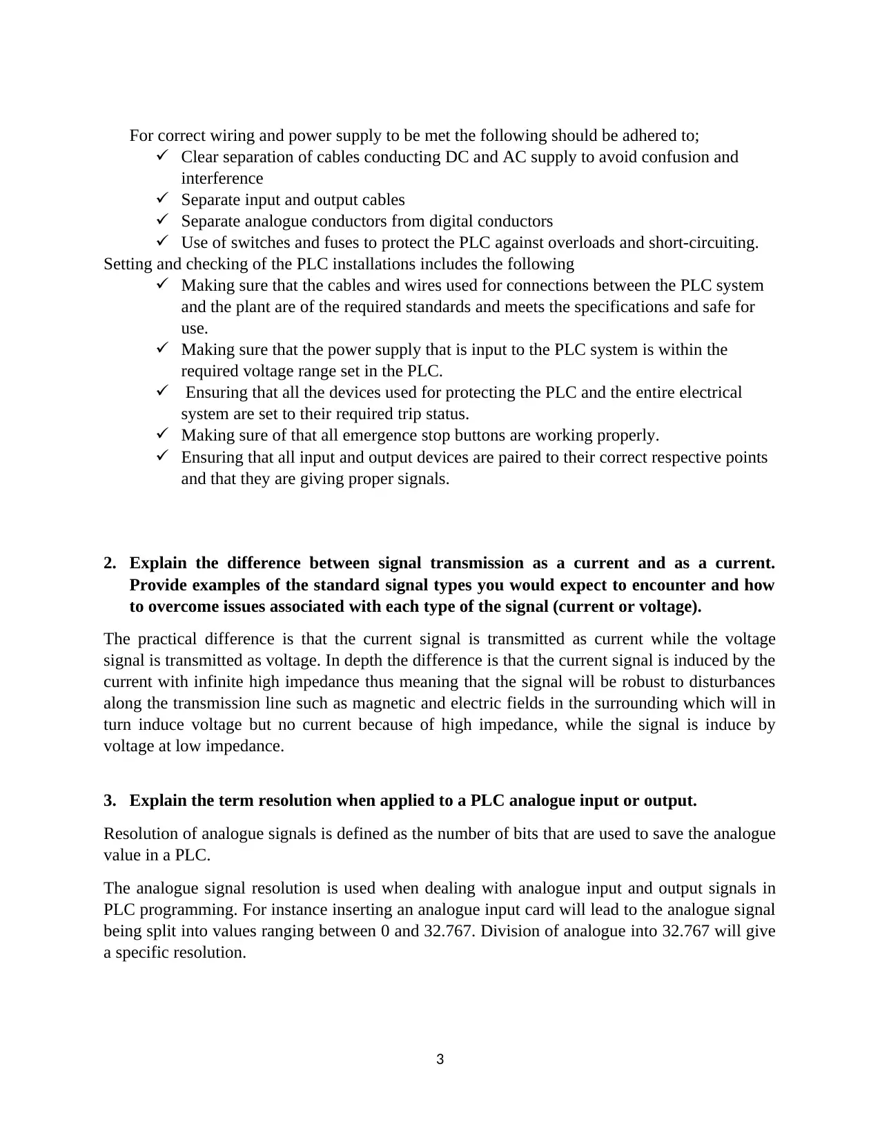
1. Using the datasheets provided on a USB flash drive, neatly sketch an example of how
you would connect; (a) 2-wire transmitter, (b) 4-wire transmitter to a micrologic analog
input module. (pt # 1762 –IF4) Both transmitters have 4-20mA outputs and the power
supply is 240V D.C.
4
analog converter on a 0-10V DC PLC analogue input module.
10-Bit DAC Converter
Voltage Output = Reference Voltage
2N−1 × Digital Number Input
¿ Vref
1023 × Din
Assuming that the reference voltage is 3.3V and digital input is 10 for 10-bit DAC
Therefore,
¿ 3.3
1023 ×10
¿ 0.032258 V
Connecting a current transmitter to an analogue input module
1. Using the datasheets provided on a USB flash drive, neatly sketch an example of how
you would connect; (a) 2-wire transmitter, (b) 4-wire transmitter to a micrologic analog
input module. (pt # 1762 –IF4) Both transmitters have 4-20mA outputs and the power
supply is 240V D.C.
4
Paraphrase This Document
Need a fresh take? Get an instant paraphrase of this document with our AI Paraphraser
2. What precautions should be taken when installing cables associates with analogue
instruments?
It is advisable to use tightly twisted pair of wires in wiring process in the control
instrumentation of analogue instruments. This is because twisted wires minimize
impacts of electromagnetic interferences and disturbances.
Addition of a grounded shield on top of twisting to provide extra protection against
electromagnetic noise and other disturbances.
Using high quality thermoplastic for insulation of cables in control instrumentation of
analogue instruments. This makes it easier for voltage to be used. Most circuit in
analogue instruments operate at 30VDC.
Avoidance of splices in instrumentation cables always.
3. There are different types of earthing systems associated with general electric items and
instrumentation systems. Describe what an instrumentation earthing system would look
like and provide a neat sketch of such an earthing system.
Earthing is defined as the process of making or building an alternative way of directing excessive
or fault electrical currents safely into the earth. This process is also enabled by offering minimal
or no resistance or impedance. In an industry earthing is both electrical earthing and
instrumentation earthing. Instrumententation earthing also called reference earth is done by
isolating all individual shields or screens from electrical earthing to avoid interference and then
connecting the shields to the instrument bus bar and then to the ground via ground dispatcher.
Instrumentation earthing is comprised of three earths namely;
1. Electrical earthing
2. Instrument earthing
3. Intrinsically safe earthing
5
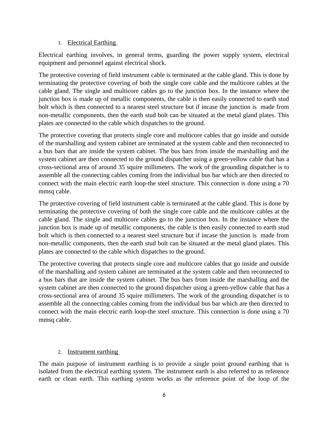
1. Electrical Earthing
Electrical earthing involves, in general terms, guarding the power supply system, electrical
equipment and personnel against electrical shock.
The protective covering of field instrument cable is terminated at the cable gland. This is done by
terminating the protective covering of both the single core cable and the multicore cables at the
cable gland. The single and multicore cables go to the junction box. In the instance where the
junction box is made up of metallic components, the cable is then easily connected to earth stud
bolt which is then connected to a nearest steel structure but if incase the junction is made from
non-metallic components, then the earth stud bolt can be situated at the metal gland plates. This
plates are connected to the cable which dispatches to the ground.
The protective covering that protects single core and multicore cables that go inside and outside
of the marshalling and system cabinet are terminated at the system cable and then reconnected to
a bus bars that are inside the system cabinet. The bus bars from inside the marshalling and the
system cabinet are then connected to the ground dispatcher using a green-yellow cable that has a
cross-sectional area of around 35 squire millimeters. The work of the grounding dispatcher is to
assemble all the connecting cables coming from the individual bus bar which are then directed to
connect with the main electric earth loop-the steel structure. This connection is done using a 70
mmsq cable.
2. Instrument earthing
The main purpose of instrument earthing is to provide a single point ground earthing that is
isolated from the electrical earthing system. The instrument earth is also referred to as reference
earth or clean earth. This earthing system works as the reference point of the loop of the
6
⊘ This is a preview!⊘
Do you want full access?
Subscribe today to unlock all pages.
Trusted by 1+ million students worldwide
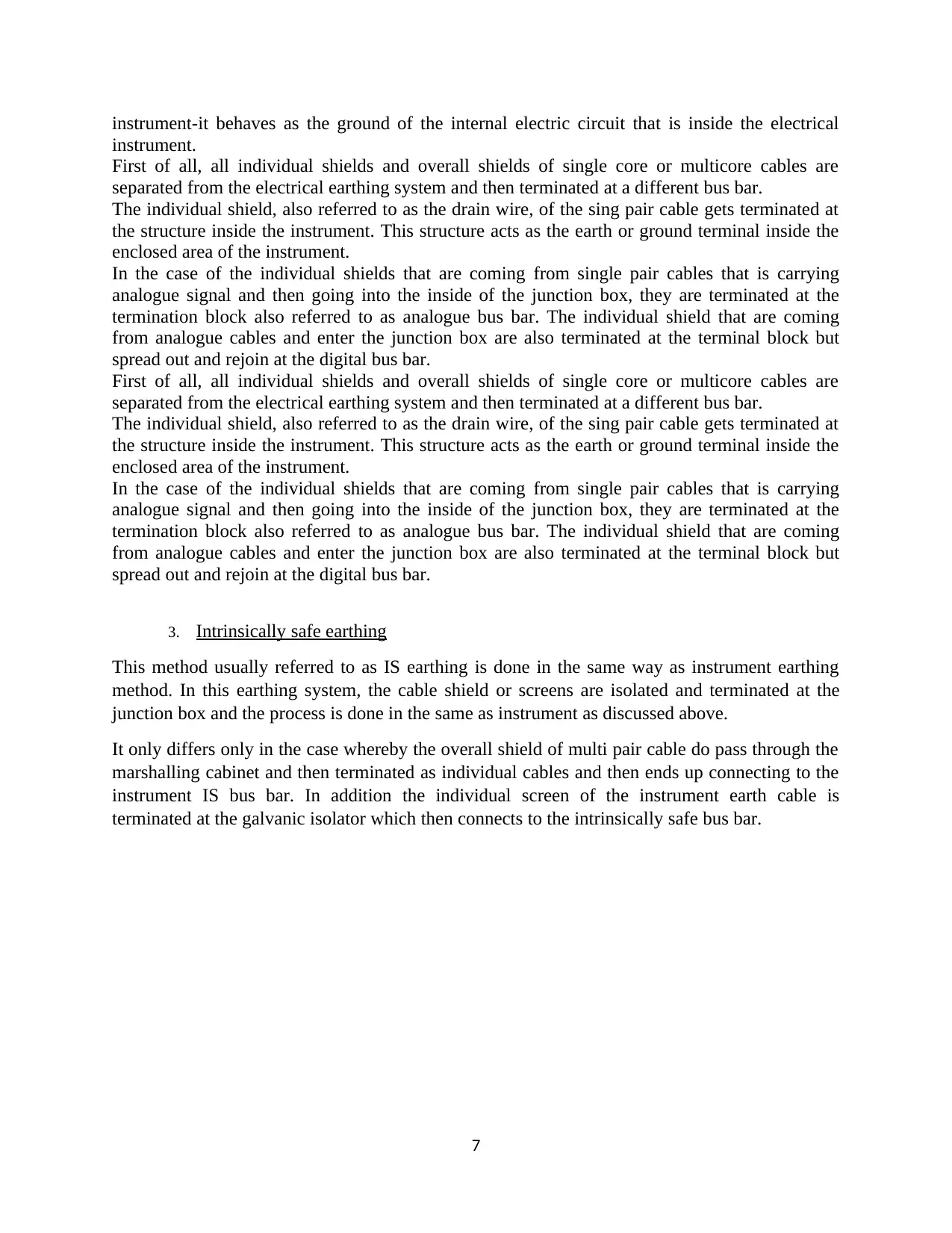
instrument-it behaves as the ground of the internal electric circuit that is inside the electrical
instrument.
First of all, all individual shields and overall shields of single core or multicore cables are
separated from the electrical earthing system and then terminated at a different bus bar.
The individual shield, also referred to as the drain wire, of the sing pair cable gets terminated at
the structure inside the instrument. This structure acts as the earth or ground terminal inside the
enclosed area of the instrument.
In the case of the individual shields that are coming from single pair cables that is carrying
analogue signal and then going into the inside of the junction box, they are terminated at the
termination block also referred to as analogue bus bar. The individual shield that are coming
from analogue cables and enter the junction box are also terminated at the terminal block but
spread out and rejoin at the digital bus bar.
3. Intrinsically safe earthing
This method usually referred to as IS earthing is done in the same way as instrument earthing
method. In this earthing system, the cable shield or screens are isolated and terminated at the
junction box and the process is done in the same as instrument as discussed above.
It only differs only in the case whereby the overall shield of multi pair cable do pass through the
marshalling cabinet and then terminated as individual cables and then ends up connecting to the
instrument IS bus bar. In addition the individual screen of the instrument earth cable is
terminated at the galvanic isolator which then connects to the intrinsically safe bus bar.
7
Paraphrase This Document
Need a fresh take? Get an instant paraphrase of this document with our AI Paraphraser
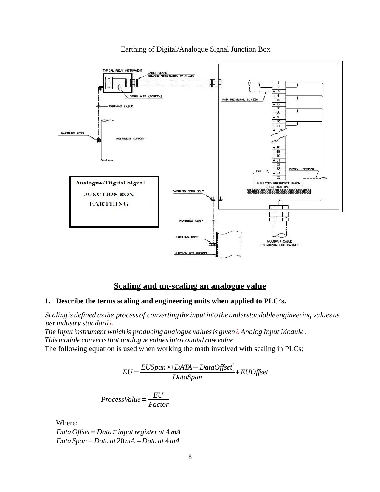
Earthing of Digital/Analogue Signal Junction Box
Scaling and un-scaling an analogue value
1. Describe the terms scaling and engineering units when applied to PLC’s.
Scalingis defined as the process of converting the input into the understandable engineering values as
per industry standard ¿
The Input instrument which is producing analogue values is given ¿ Analog Input Module .
This module converts that analogue values into counts/raw value
The following equation is used when working the math involved with scaling in PLCs;
EU = EUSpan × ( DATA− DataOffset )
DataSpan + EUOffset
ProcessValue= EU
Factor
Where;
Data Offset=Data∈input register at 4 mA
Data Span=Data at 20 mA – Data at 4 mA
8
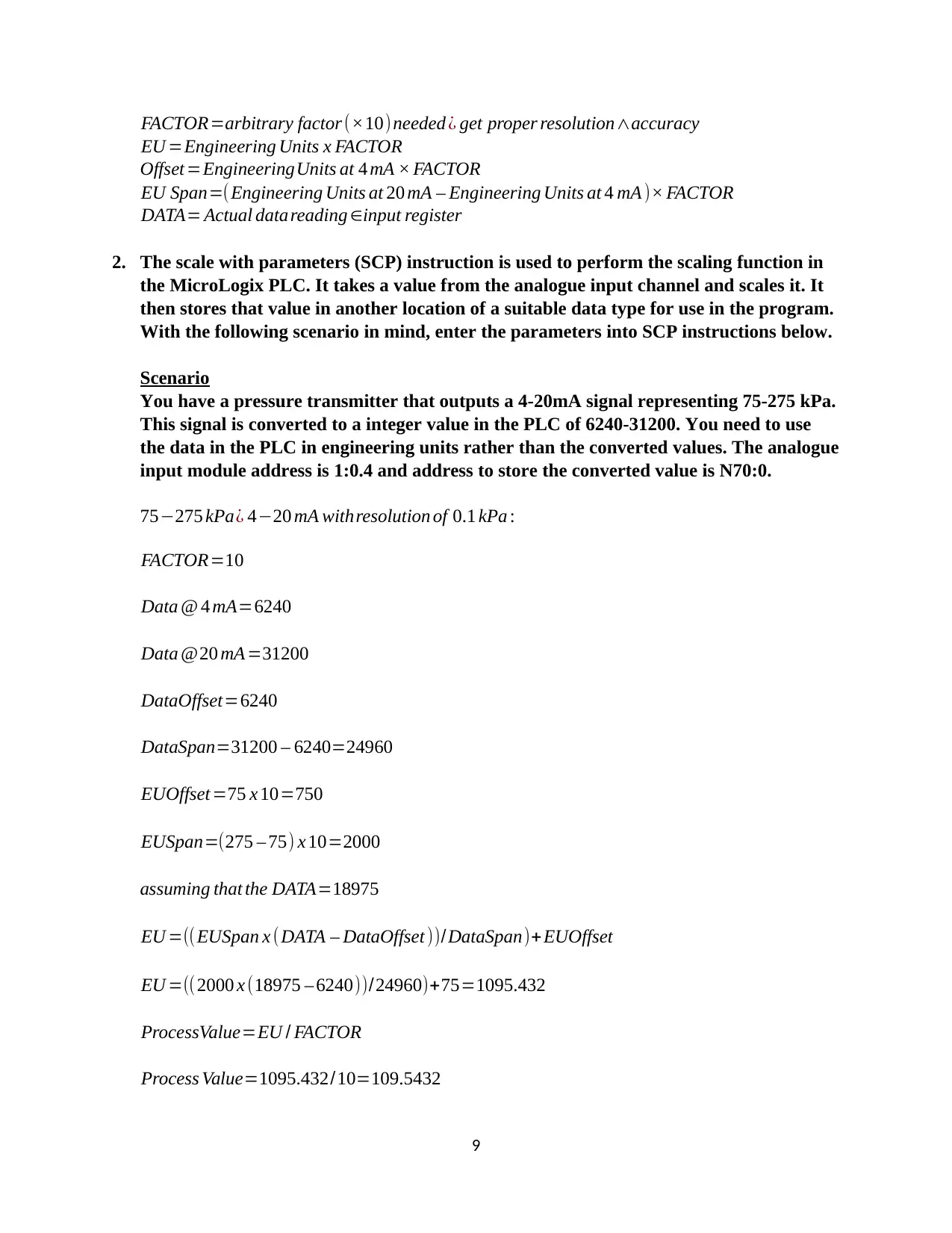
FACTOR=arbitrary factor (×10)needed ¿ get proper resolution∧accuracy
EU =Engineering Units x FACTOR
Offset =EngineeringUnits at 4 mA × FACTOR
EU Span=(Engineering Units at 20 mA – Engineering Units at 4 mA )× FACTOR
DATA= Actual datareading ∈input register
2. The scale with parameters (SCP) instruction is used to perform the scaling function in
the MicroLogix PLC. It takes a value from the analogue input channel and scales it. It
then stores that value in another location of a suitable data type for use in the program.
With the following scenario in mind, enter the parameters into SCP instructions below.
Scenario
You have a pressure transmitter that outputs a 4-20mA signal representing 75-275 kPa.
This signal is converted to a integer value in the PLC of 6240-31200. You need to use
the data in the PLC in engineering units rather than the converted values. The analogue
input module address is 1:0.4 and address to store the converted value is N70:0.
75−275 kPa¿ 4−20 mA withresolution of 0.1 kPa :
FACTOR=10
Data @ 4 mA=6240
Data @20 mA =31200
DataOffset=6240
DataSpan=31200 – 6240=24960
EUOffset =75 x 10=750
EUSpan=(275 – 75) x 10=2000
assuming that the DATA=18975
EU =((EUSpan x (DATA – DataOffset ))/DataSpan)+ EUOffset
EU =((2000 x (18975 – 6240))/24960)+75=1095.432
ProcessValue=EU / FACTOR
Process Value=1095.432/10=109.5432
9
⊘ This is a preview!⊘
Do you want full access?
Subscribe today to unlock all pages.
Trusted by 1+ million students worldwide
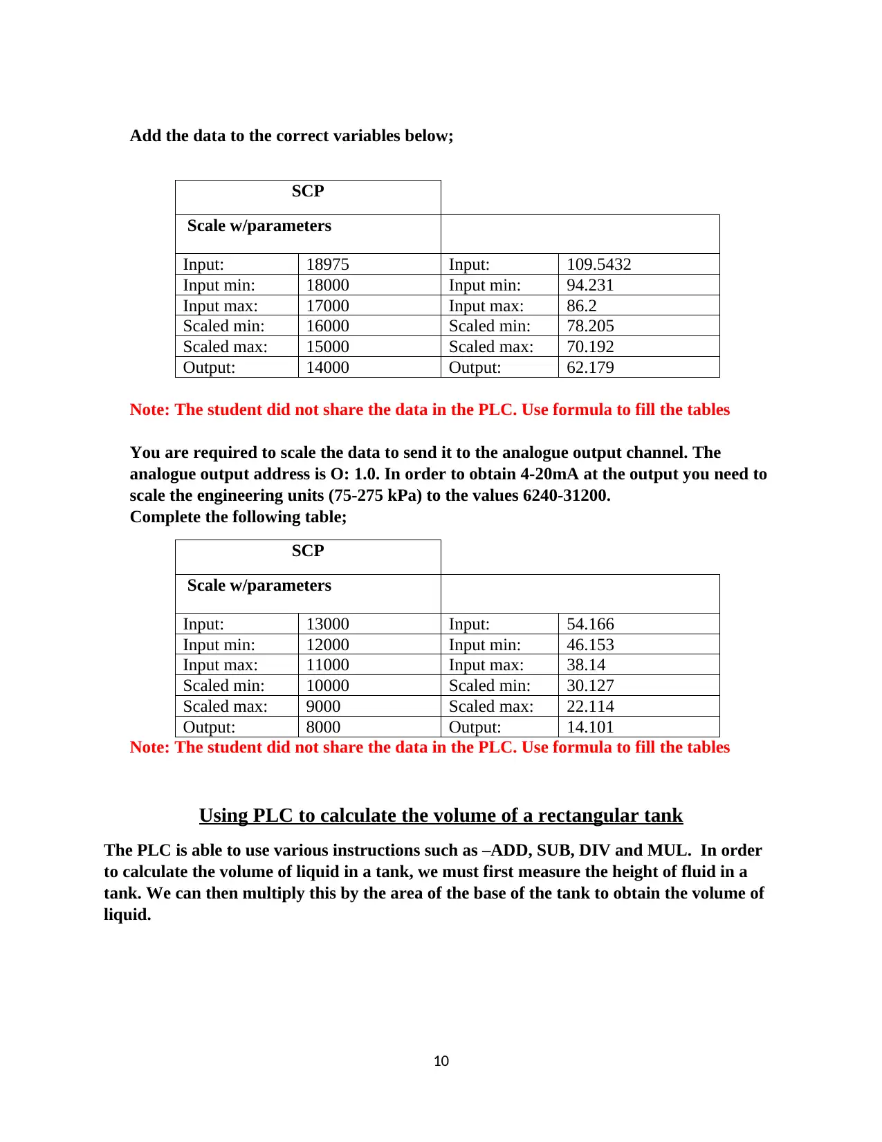
Add the data to the correct variables below;
SCP
Scale w/parameters
Input: 18975 Input: 109.5432
Input min: 18000 Input min: 94.231
Input max: 17000 Input max: 86.2
Scaled min: 16000 Scaled min: 78.205
Scaled max: 15000 Scaled max: 70.192
Output: 14000 Output: 62.179
Note: The student did not share the data in the PLC. Use formula to fill the tables
You are required to scale the data to send it to the analogue output channel. The
analogue output address is O: 1.0. In order to obtain 4-20mA at the output you need to
scale the engineering units (75-275 kPa) to the values 6240-31200.
Complete the following table;
SCP
Scale w/parameters
Input: 13000 Input: 54.166
Input min: 12000 Input min: 46.153
Input max: 11000 Input max: 38.14
Scaled min: 10000 Scaled min: 30.127
Scaled max: 9000 Scaled max: 22.114
Output: 8000 Output: 14.101
Note: The student did not share the data in the PLC. Use formula to fill the tables
Using PLC to calculate the volume of a rectangular tank
The PLC is able to use various instructions such as –ADD, SUB, DIV and MUL. In order
to calculate the volume of liquid in a tank, we must first measure the height of fluid in a
tank. We can then multiply this by the area of the base of the tank to obtain the volume of
liquid.
10
SCP
Scale w/parameters
Input: 18975 Input: 109.5432
Input min: 18000 Input min: 94.231
Input max: 17000 Input max: 86.2
Scaled min: 16000 Scaled min: 78.205
Scaled max: 15000 Scaled max: 70.192
Output: 14000 Output: 62.179
Note: The student did not share the data in the PLC. Use formula to fill the tables
You are required to scale the data to send it to the analogue output channel. The
analogue output address is O: 1.0. In order to obtain 4-20mA at the output you need to
scale the engineering units (75-275 kPa) to the values 6240-31200.
Complete the following table;
SCP
Scale w/parameters
Input: 13000 Input: 54.166
Input min: 12000 Input min: 46.153
Input max: 11000 Input max: 38.14
Scaled min: 10000 Scaled min: 30.127
Scaled max: 9000 Scaled max: 22.114
Output: 8000 Output: 14.101
Note: The student did not share the data in the PLC. Use formula to fill the tables
Using PLC to calculate the volume of a rectangular tank
The PLC is able to use various instructions such as –ADD, SUB, DIV and MUL. In order
to calculate the volume of liquid in a tank, we must first measure the height of fluid in a
tank. We can then multiply this by the area of the base of the tank to obtain the volume of
liquid.
10
Paraphrase This Document
Need a fresh take? Get an instant paraphrase of this document with our AI Paraphraser
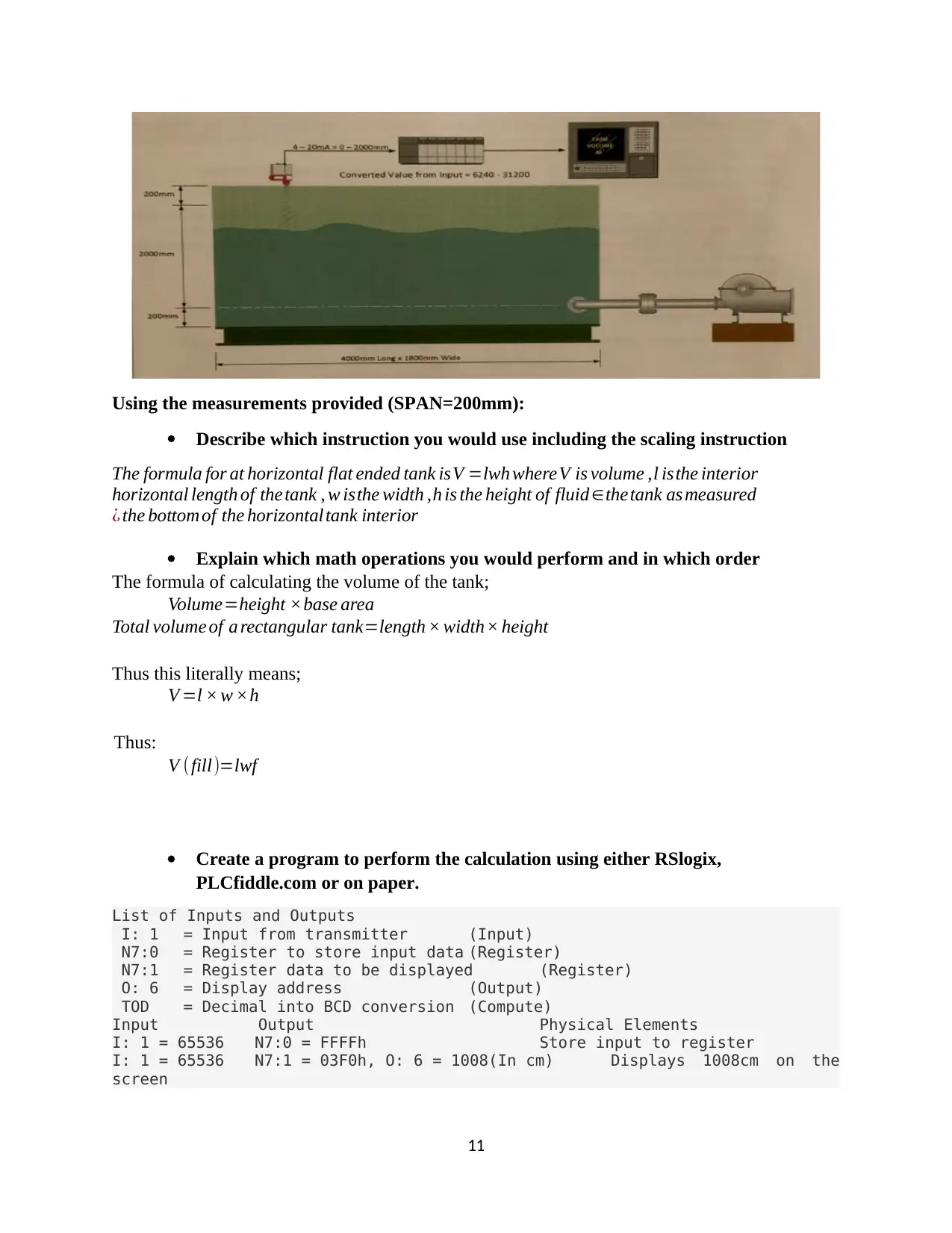
Using the measurements provided (SPAN=200mm):
Describe which instruction you would use including the scaling instruction
The formula for at horizontal flat ended tank isV =lwh whereV is volume ,l isthe interior
horizontal length of thetank , w isthe width ,h is the height of fluid ∈thetank as measured
¿ the bottom of the horizontaltank interior
Explain which math operations you would perform and in which order
The formula of calculating the volume of the tank;
Volume=height ×base area
Total volume of a rectangular tank=length × width× height
Thus this literally means;
V =l × w ×h
Thus:
V (fill)=lwf
Create a program to perform the calculation using either RSlogix,
PLCfiddle.com or on paper.
List of Inputs and Outputs
I: 1 = Input from transmitter (Input)
N7:0 = Register to store input data (Register)
N7:1 = Register data to be displayed (Register)
O: 6 = Display address (Output)
TOD = Decimal into BCD conversion (Compute)
Input Output Physical Elements
I: 1 = 65536 N7:0 = FFFFh Store input to register
I: 1 = 65536 N7:1 = 03F0h, O: 6 = 1008(In cm) Displays 1008cm on the
screen
11
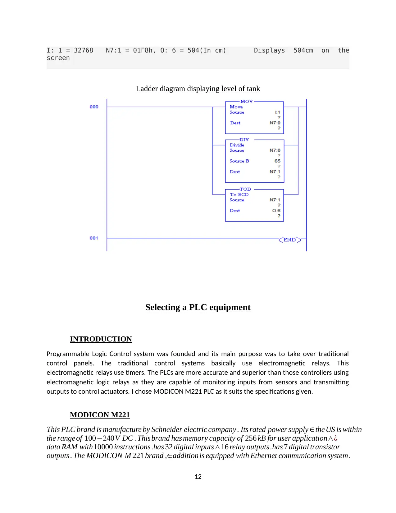
I: 1 = 32768 N7:1 = 01F8h, O: 6 = 504(In cm) Displays 504cm on the
screen
Ladder diagram displaying level of tank
Selecting a PLC equipment
INTRODUCTION
Programmable Logic Control system was founded and its main purpose was to take over traditional
control panels. The traditional control systems basically use electromagnetic relays. This
electromagnetic relays use timers. The PLCs are more accurate and superior than those controllers using
electromagnetic logic relays as they are capable of monitoring inputs from sensors and transmitting
outputs to control actuators. I chose MODICON M221 PLC as it suits the specifications given.
MODICON M221
This PLC brand is manufacture by Schneider electric company . Its rated power supply ∈theUS is within
the range of 100−240V DC . Thisbrand has memory capacity of 256 kB for user application∧¿
data RAM with10000 instructions .has 32 digital inputs∧16 relay outputs .has 7 digital transistor
outputs . The MODICON M 221 brand ,∈addition is equipped with Ethernet communication system .
12
⊘ This is a preview!⊘
Do you want full access?
Subscribe today to unlock all pages.
Trusted by 1+ million students worldwide
1 out of 14


Your All-in-One AI-Powered Toolkit for Academic Success.
+13062052269
info@desklib.com
Available 24*7 on WhatsApp / Email
![[object Object]](/_next/static/media/star-bottom.7253800d.svg)
Unlock your academic potential
Copyright © 2020–2026 A2Z Services. All Rights Reserved. Developed and managed by ZUCOL.