Advanced Pneumatic and Hydraulic Systems Design - TU Engineering

Verified

Added on  2023/06/11

|20
|2101
|384
Practical Assignment
AI Summary
This assignment provides detailed solutions to problems related to pneumatic and hydraulic systems, covering topics such as circuit design, component analysis, and system operation. It includes explanations of pneumatic circuit diagrams with directional control valves, check valves, and sequence valves. The assignment also addresses hydraulic circuits using cascade systems, modifications for emergency retraction, and the integration of electronic controllers. Further, it delves into rotary actuators, multistage compressors, and the operational principles of rotary vane compressors. Calculations for system pressure and flow rates are provided, along with discussions on variable displacement axial piston pumps and positive displacement compressors. The document also covers air drying methods, material selection for distribution mains, and lubrication techniques. The assignment concludes with troubleshooting tips for overheating compressors, a system monitoring chart, and precautions for changing hydraulic fluids. This resource is contributed by a student and is available on Desklib, where students can find a wide range of study tools and solved assignments.
Document Page
SOLUTION TO THE QUESTIONS
1. (a)
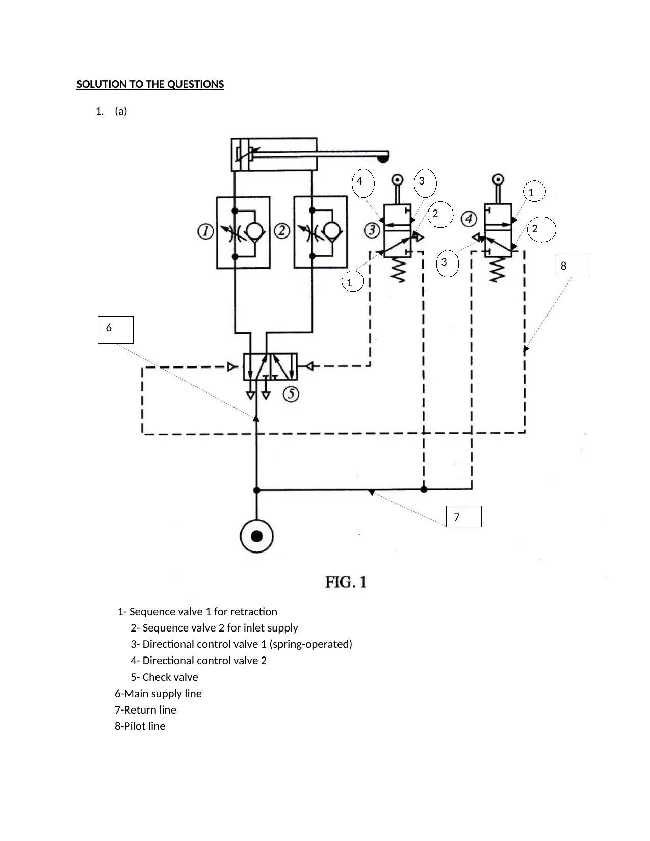
1- Sequence valve 1 for retraction
2- Sequence valve 2 for inlet supply
3- Directional control valve 1 (spring-operated)
4- Directional control valve 2
5- Check valve
6-Main supply line
7-Return line
8-Pilot line
6
8
7
1
2
3
3
2
1
4
tabler-icon-diamond-filled.svg

Paraphrase This Document

Need a fresh take? Get an instant paraphrase of this document with our AI Paraphraser
Document Page
(b) Directional control valves, check valves, sequence valves
DCV 1: 3 position, 4 way and spring operated
DCV2: 3 position, 4 way and spring operated
(Check figure 1 for ports numbering)
(c) The cylinder section
Control valves constituting directional control valve
Actuator –pneumatic drive
Return line
(d) How system works
-During inlet supply to cylinder, valve 2 is closed while 1 is left opened
-Air rushes through valve 1
-The check valve ensures correct sequencing is followed
-As the plunger pushes forward and the check valve closes line 1 hence valve is closed
-The compressed air exits via valve 2 and is directed to the action centre
(e) Functions of (1) and (2):
1- Regulates flow of air into cylinder for extensions
2-Regulates flow of air out of cylinder in retraction mode
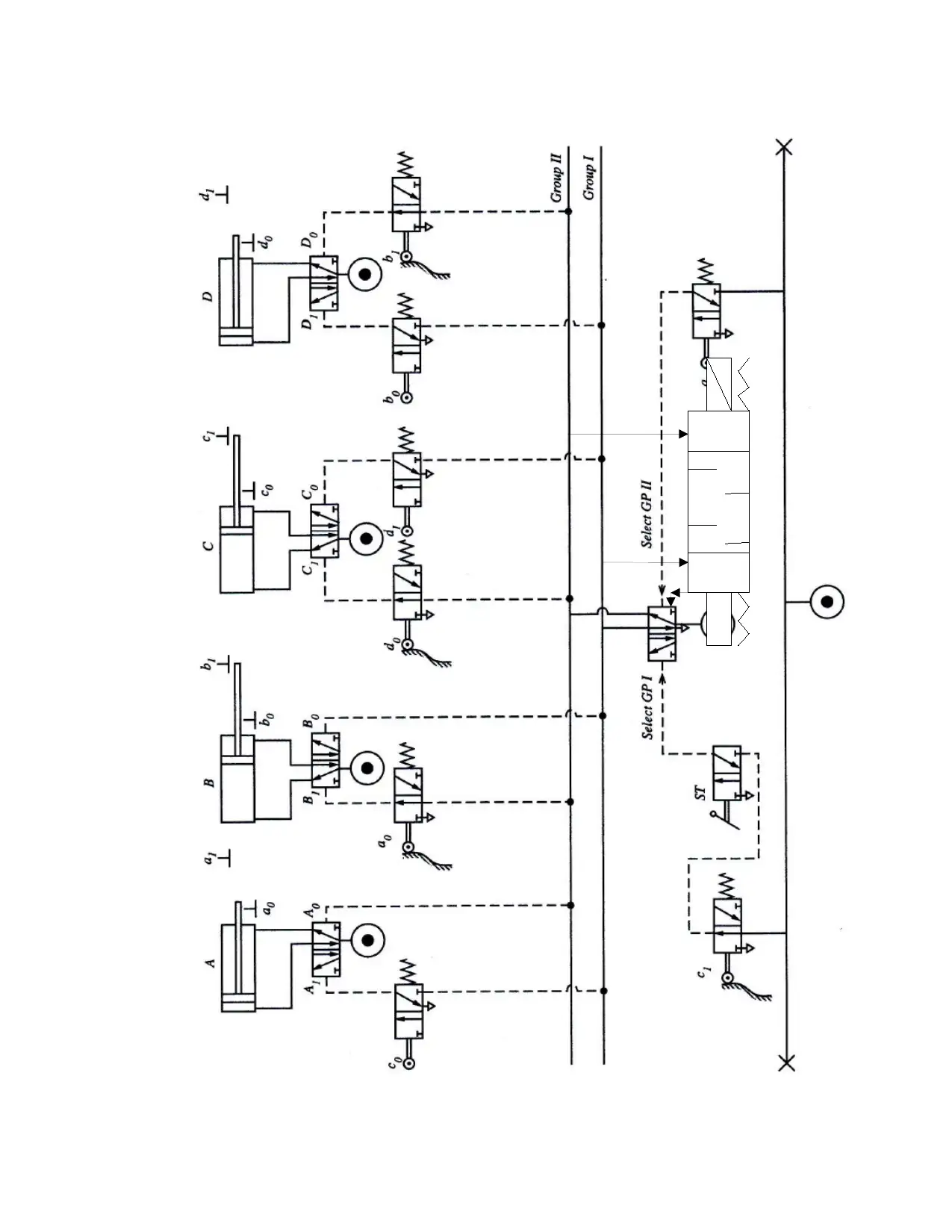
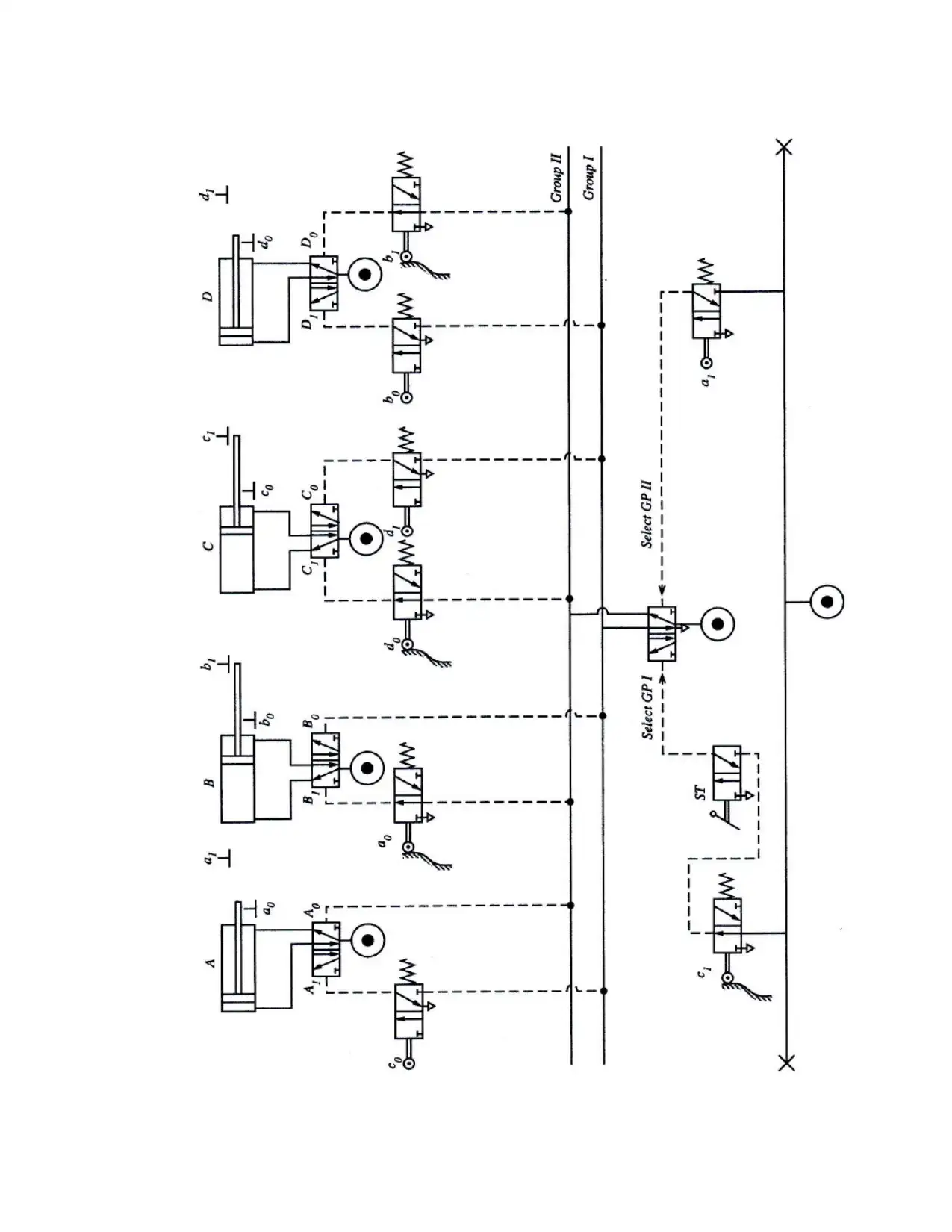
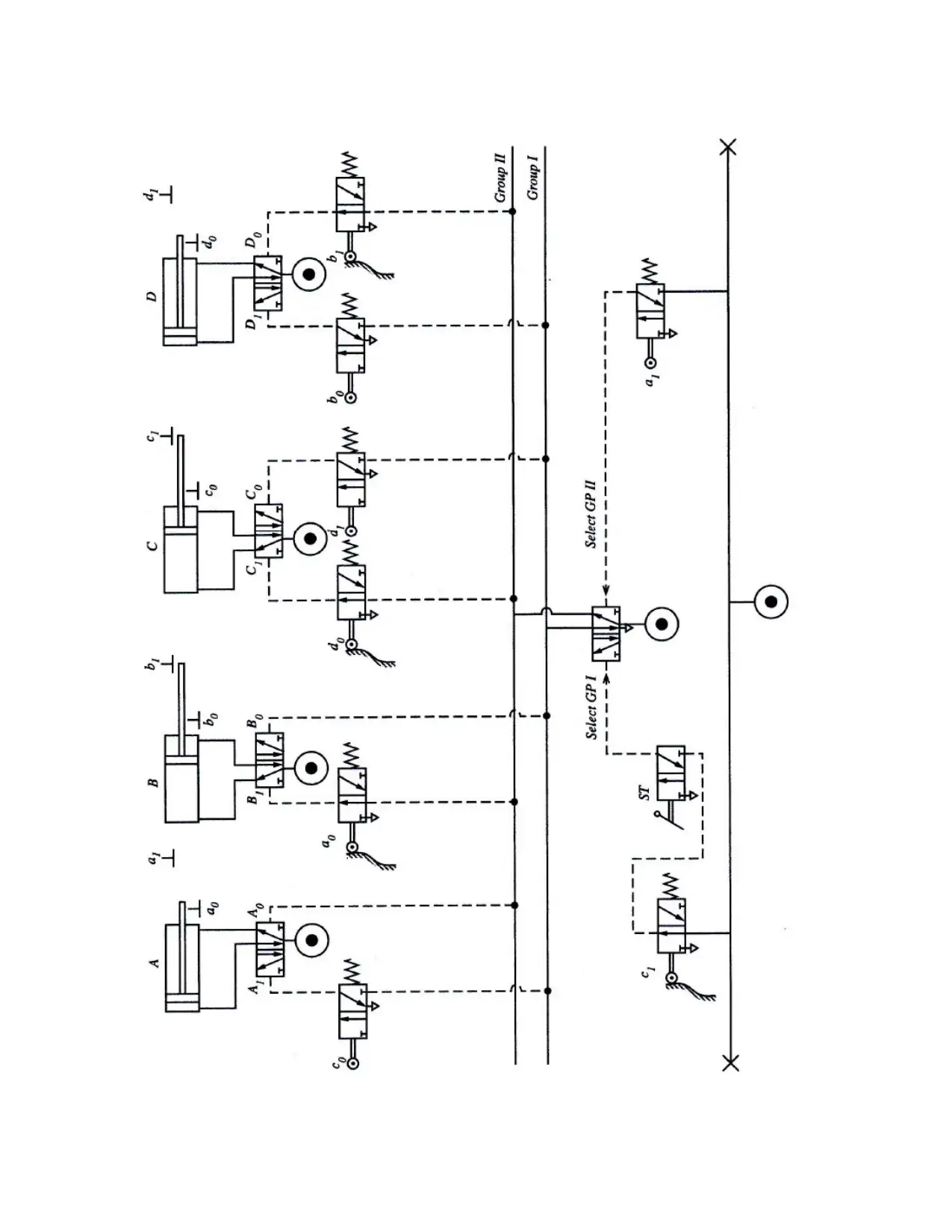
2. (a) -A,+B,+C,-D and the return : +D,-C,-B,+A full cycle
(b) Electronics controller integration
The controller shown is integrated in circuit figure 2 below
Document Page
Document Page
tabler-icon-diamond-filled.svg

Paraphrase This Document

Need a fresh take? Get an instant paraphrase of this document with our AI Paraphraser
Document Page
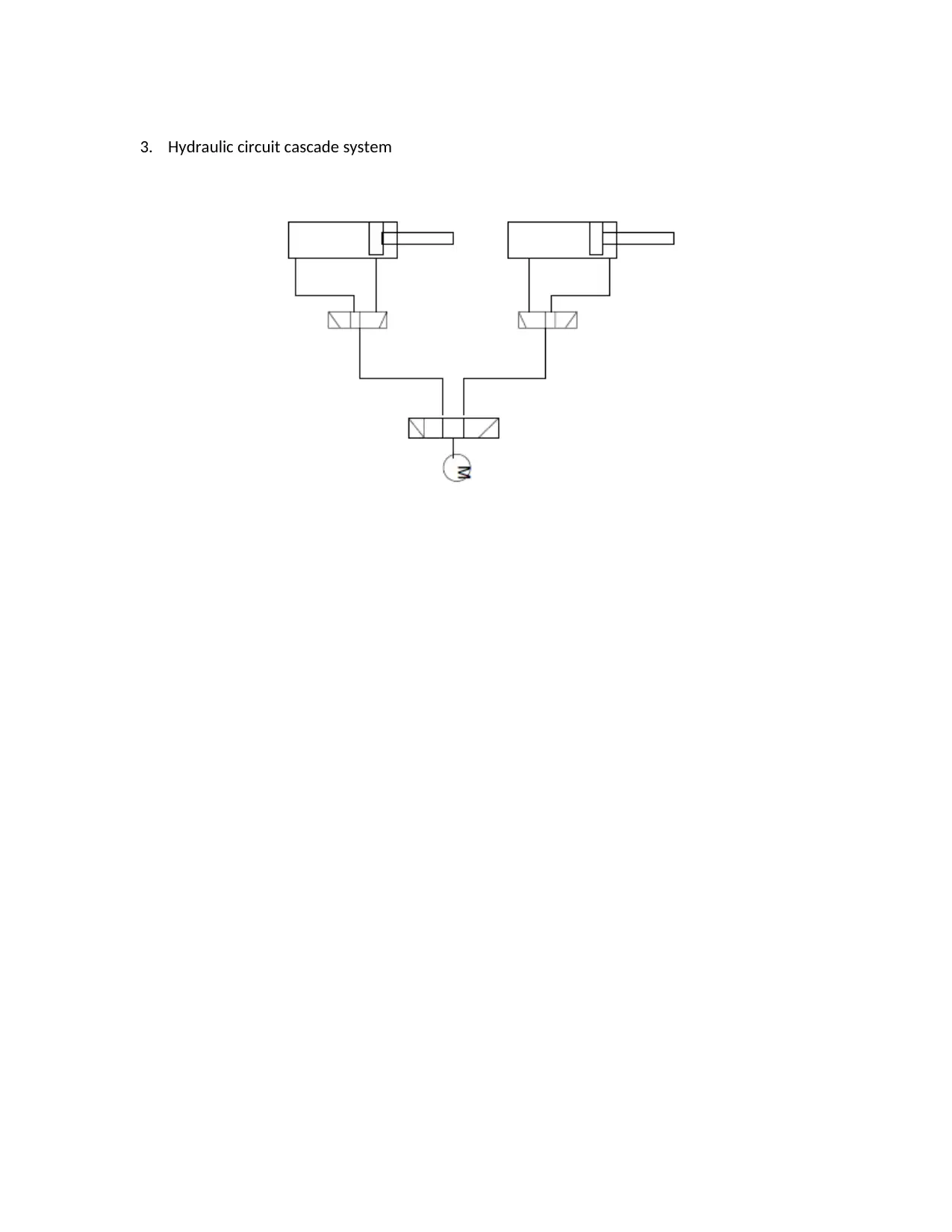
3. Hydraulic circuit cascade system
Document Page
Document Page
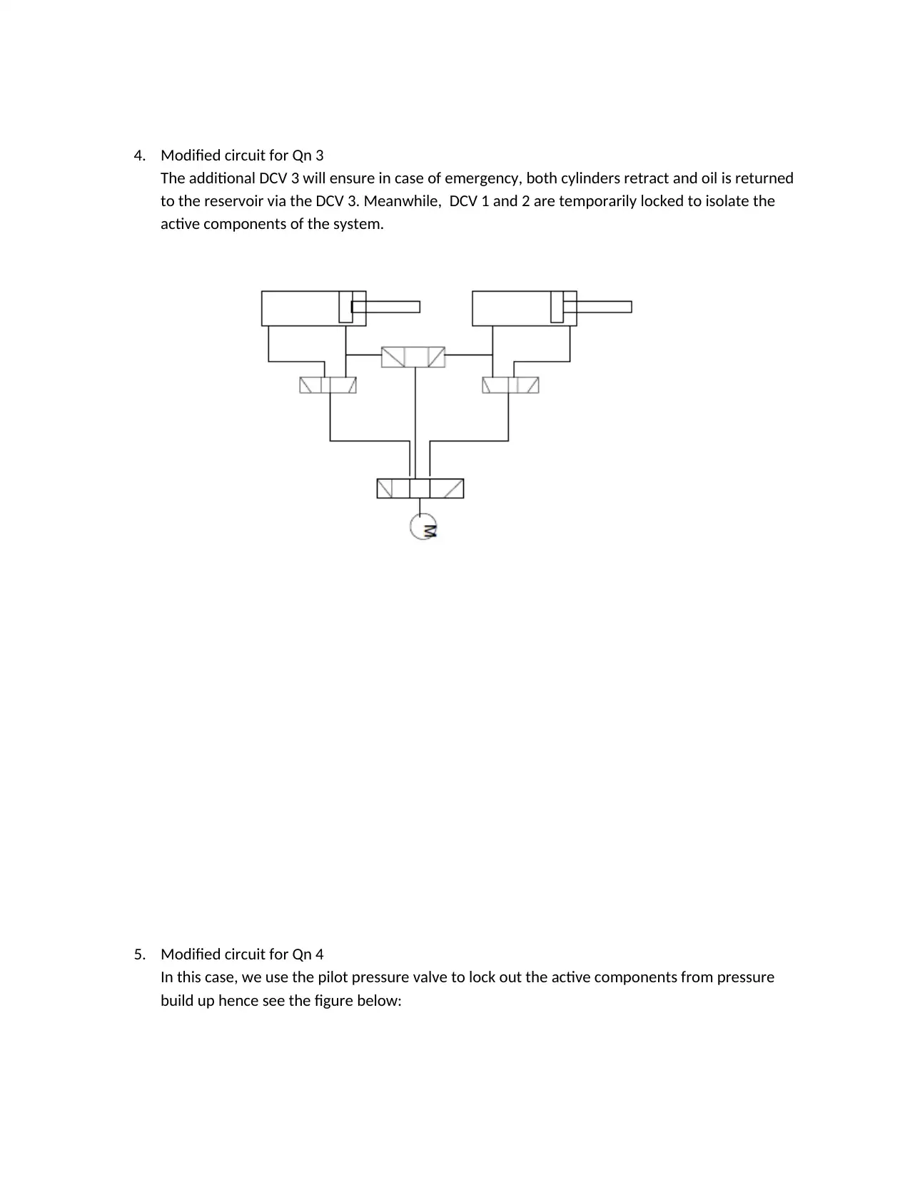
4. Modified circuit for Qn 3
The additional DCV 3 will ensure in case of emergency, both cylinders retract and oil is returned
to the reservoir via the DCV 3. Meanwhile, DCV 1 and 2 are temporarily locked to isolate the
active components of the system.
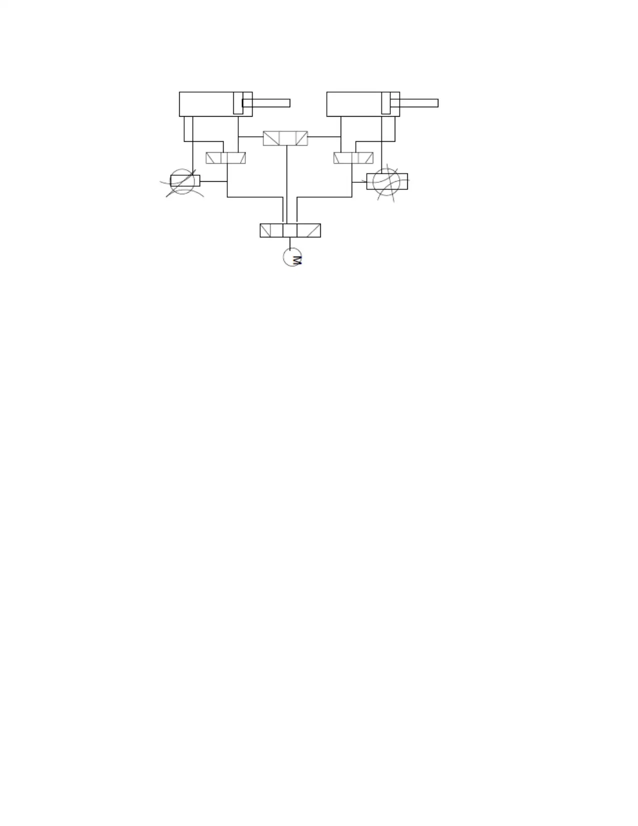
5. Modified circuit for Qn 4
In this case, we use the pilot pressure valve to lock out the active components from pressure
build up hence see the figure below:
tabler-icon-diamond-filled.svg

Paraphrase This Document

Need a fresh take? Get an instant paraphrase of this document with our AI Paraphraser
Document Page
Document Page
Document Page
6. (a) A-Rotary actuator: Provides a means of driving the system in a rotational manner
B-3-way, 4port DCV: Regulates flow of oil in the main supply circuit
C-3-way, 4port DCV: Regulates flow of oil in the return line circuit
D- Gate valve: Determines the amount of oil allowable in the system from the reservoir
E- motor: Converts power to mechanical from electrical hence the pressure energy is derived
F- Sequence valves: For drive sequencing be it extension or retraction.
(b) The rotary actuator receives controlled actions from the motor drive via the sequence and
DCV valves. It operates two sets of drive functions of compression such that actuator delivers
power to either of the two. The valves regulate flow and pressure.
The limitation is that since the circuit has no speed control mechanism such that the actuation
speed is wholly transferred to either of the design drive points without speed regulation
tabler-icon-diamond-filled.svg

Paraphrase This Document

Need a fresh take? Get an instant paraphrase of this document with our AI Paraphraser
Document Page
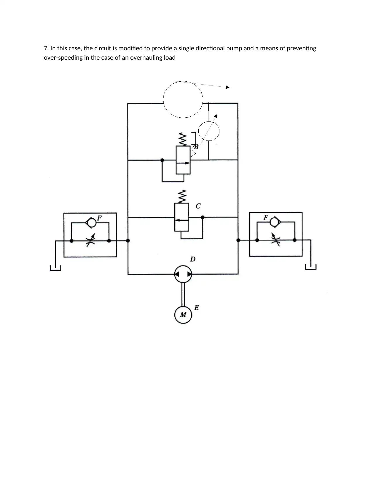
7. In this case, the circuit is modified to provide a single directional pump and a means of preventing
over-speeding in the case of an overhauling load
Document Page
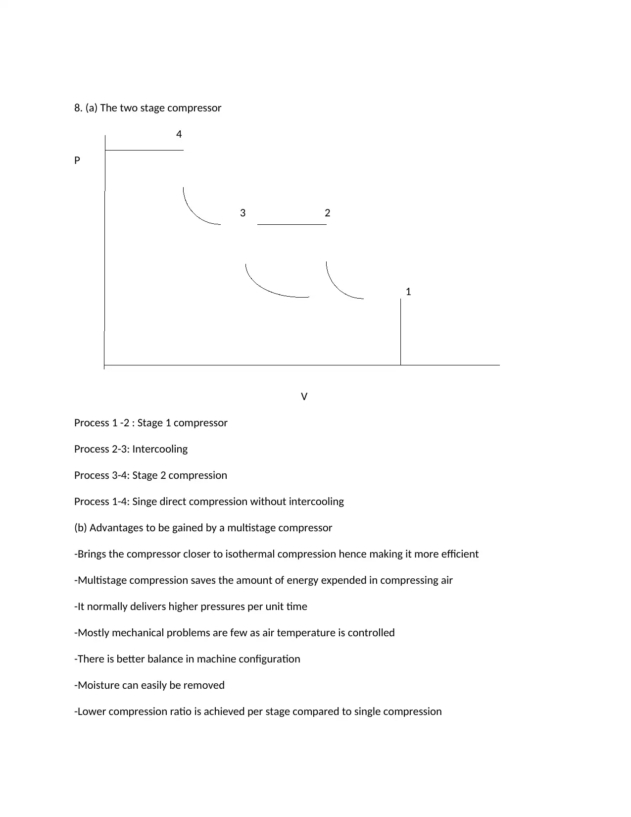
8. (a) The two stage compressor
4
P
3 2
1
V
Process 1 -2 : Stage 1 compressor
Process 2-3: Intercooling
Process 3-4: Stage 2 compression
Process 1-4: Singe direct compression without intercooling
(b) Advantages to be gained by a multistage compressor
-Brings the compressor closer to isothermal compression hence making it more efficient
-Multistage compression saves the amount of energy expended in compressing air
-It normally delivers higher pressures per unit time
-Mostly mechanical problems are few as air temperature is controlled
-There is better balance in machine configuration
-Moisture can easily be removed
-Lower compression ratio is achieved per stage compared to single compression
chevron_up_icon
1 out of 20
circle_padding
hide_on_mobile
zoom_out_icon
[object Object]