Power Electronic Applications for Energy Systems Solutions

Verified

Added on  2020/05/16

|3
|729
|162
Homework Assignment
AI Summary
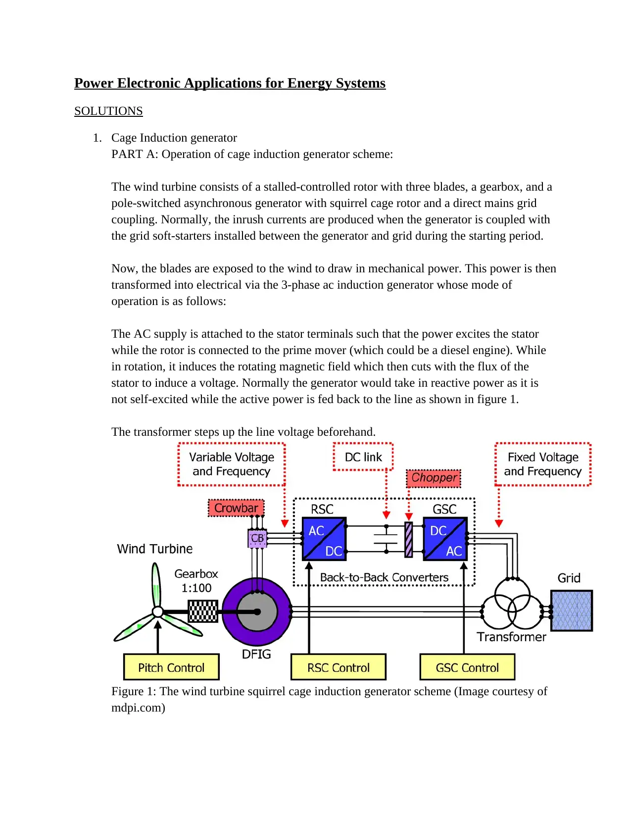
This document presents solutions to a power electronics assignment focused on energy systems. Part A explains the operation of a cage induction generator scheme, including the role of soft-starters and the transformation of mechanical power to electrical power in a wind turbine setup. It details the stator and rotor interactions, the rotating magnetic field, and the advantages of varying the generator's speed. Part B delves into self-excited induction generators, outlining their operational mechanism without external sources and their application in wind turbines, both in fixed-speed and variable-speed systems. It includes a calculation for the minimum capacitance required per phase in a delta-connected machine. The document also explains the generating mode of operation of a wound-rotor doubly-fed induction generator (DFIG) with the aid of power flow diagrams and equations, covering sub-synchronous and super-synchronous speeds and the role of voltage source converters.
tabler-icon-diamond-filled.svg

Contribute Materials

Your contribution can guide someone’s learning journey. Share your documents today.
Document Page
Power Electronic Applications for Energy Systems
SOLUTIONS
1. Cage Induction generator
PART A: Operation of cage induction generator scheme:
The wind turbine consists of a stalled-controlled rotor with three blades, a gearbox, and a
pole-switched asynchronous generator with squirrel cage rotor and a direct mains grid
coupling. Normally, the inrush currents are produced when the generator is coupled with
the grid soft-starters installed between the generator and grid during the starting period.
Now, the blades are exposed to the wind to draw in mechanical power. This power is then
transformed into electrical via the 3-phase ac induction generator whose mode of
operation is as follows:
The AC supply is attached to the stator terminals such that the power excites the stator
while the rotor is connected to the prime mover (which could be a diesel engine). While
in rotation, it induces the rotating magnetic field which then cuts with the flux of the
stator to induce a voltage. Normally the generator would take in reactive power as it is
not self-excited while the active power is fed back to the line as shown in figure 1.
The transformer steps up the line voltage beforehand.
Figure 1: The wind turbine squirrel cage induction generator scheme (Image courtesy of
mdpi.com)
tabler-icon-diamond-filled.svg

Secure Best Marks with AI Grader

Need help grading? Try our AI Grader for instant feedback on your assignments.
Document Page
In the above case, the generator has got both the rotating and stationary portions, such that the
rotor turns to cut the flux of the magnetic fields. The rotating magnetizing field would move at
the synchronous speed with respect to the stator. Meanwhile, the induced voltage is directly
proportional to the magnetic field strength, speed w of the rotor neglecting the losses through the
field leakage and winding losses.
In most cases, the stator is normally connected to the grid directly and the rotor is connected to
the power electronic system. For a full-rated power, this becomes more advantageous given the
nominal speed of the generator can be varied accordingly to supply more active power.
PART B:
(a) (i) Explanation of the self-excited induction generator
In self-excited induction generator, normally the system does not need an external
source starter instead they are controlled using a self-directed capacitive mechanism
where during generator turning, the capacitors get charged and once the DC source is
removed, the capacitors supply charge to restart the machine.
(ii) Its practical application for wind turbines
In Fixed-speed system where generator is attached to the main source grid
In variable speed system, it is connected to the power electronic system from which
power to the grid can be relayed.
(b) A 400V 3-phase cage induction machine has a rated current of 35A and a full load
power factor of 0.86lagging. The machine is to be run as a self-excited generator.
Calculate the minimum capacitance required per phase if the machine is connected in
delta
Firstly, we obtain the current per single line, Is= I/(3)0.5= 35/(3)0.5= 20.21A
Note that Cos ϕ= pf= 0.86, ϕ= Cos-1(0.86)= 30.7
Next, we get the total impedance Z(given the capacitor is in parallel with other active
elements combined) hence : Z= V/I
But for delta connection, the supply voltage is equivalent to the line voltage hence
V1= Vs= 400v
Z= 400<0/20.21<30.7= 19.79<-30.7
In rectangular form: 17.01-j10.104
The equivalent impedance Z= 1/R+1/jwC
Therefore 1/jwc= -j10.104
1/wc= 10.104
Hence C= 0.09897/wF
Document Page
2. Wound-rotor doubly –fed induction generator (DFIG) in which the voltage source
converters are deployed. With the aid of power flow diagrams, appropriate equations,
explain the generating mode of operation at:
DFIG has its stator connected directly to the power grid while the frequency converter
provides the connection with the rotor. This is normally configured with a back to back
capacitor to provide starter functionality.
(a) Sub-synchronous speeds
The rotor speed is very low compared in this case. A constant excitation voltage is
normally applied to keep the speed low
(b) Super-synchronous speeds
The rotor moves at a higher speed. Variable frequency drive facilitates higher speed
movements of the rotor.
chevron_up_icon
1 out of 3
circle_padding
hide_on_mobile
zoom_out_icon
logo.png

Your All-in-One AI-Powered Toolkit for Academic Success.

Available 24*7 on WhatsApp / Email

[object Object]