Power Factor Correction in RLC Circuit Fundamentals: Detailed Report

Verified

Added on  2022/08/21

|3
|687
|24
Report
AI Summary
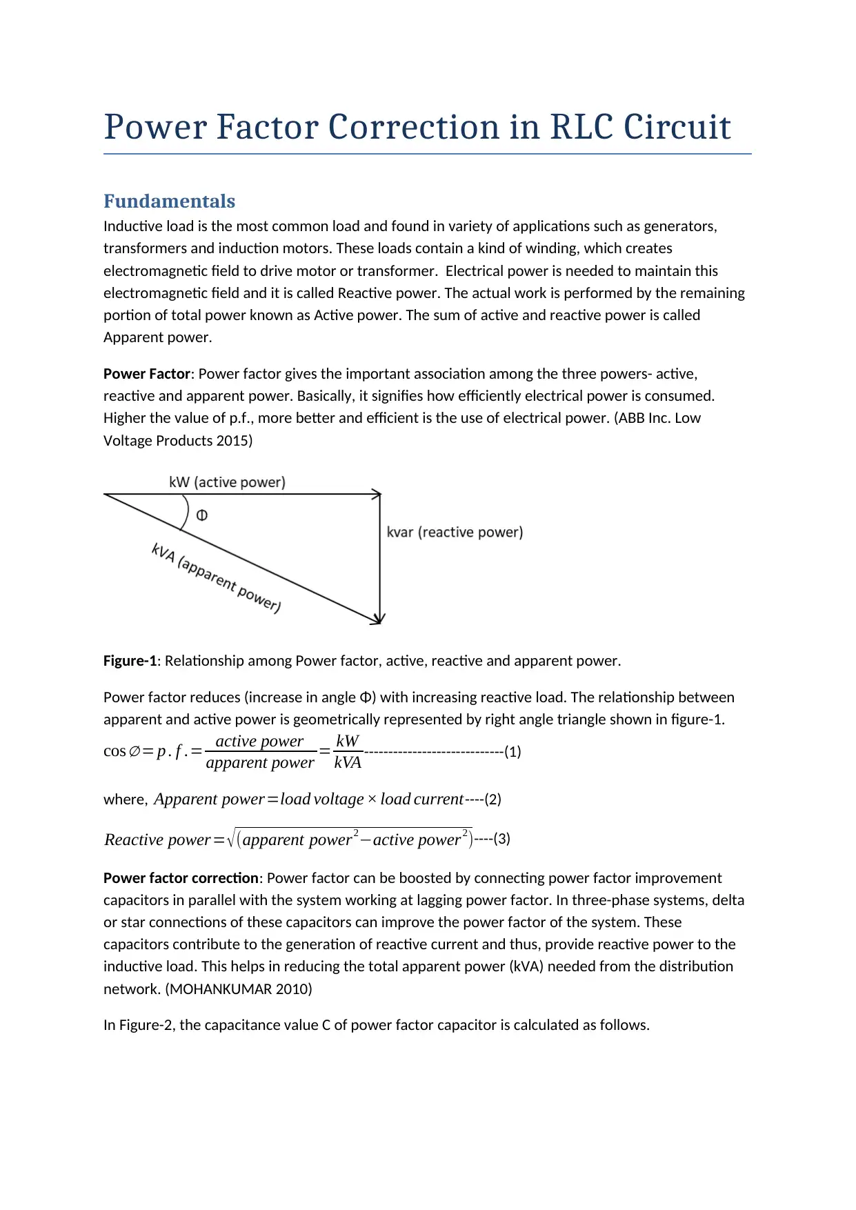
This report provides a comprehensive overview of power factor correction in RLC circuits. It begins by explaining the fundamentals of inductive loads, reactive power, and the relationship between active, reactive, and apparent power. The concept of power factor and its significance in electrical power consumption is then discussed. The report details the method of power factor correction using capacitors, including the calculation of capacitance values. Furthermore, it highlights the benefits of power factor correction, such as avoiding penalties, reducing electricity bills, enhancing load carrying capability, improving voltage, and reducing power system losses. The report also addresses the potential issue of power factor overcorrection and its consequences. The content is supported by references to relevant sources, offering a well-rounded understanding of the topic.
Document Page
Power Factor Correction in RLC Circuit
Fundamentals
Inductive load is the most common load and found in variety of applications such as generators,
transformers and induction motors. These loads contain a kind of winding, which creates
electromagnetic field to drive motor or transformer. Electrical power is needed to maintain this
electromagnetic field and it is called Reactive power. The actual work is performed by the remaining
portion of total power known as Active power. The sum of active and reactive power is called
Apparent power.
Power Factor: Power factor gives the important association among the three powers- active,
reactive and apparent power. Basically, it signifies how efficiently electrical power is consumed.
Higher the value of p.f., more better and efficient is the use of electrical power. (ABB Inc. Low
Voltage Products 2015)
Figure-1: Relationship among Power factor, active, reactive and apparent power.
Power factor reduces (increase in angle Φ) with increasing reactive load. The relationship between
apparent and active power is geometrically represented by right angle triangle shown in figure-1.
cos = p . f .= active power
apparent power = kW
kVA -----------------------------(1)
where, Apparent power=load voltage × load current----(2)
Reactive power= (apparent power2active power2)----(3)
Power factor correction: Power factor can be boosted by connecting power factor improvement
capacitors in parallel with the system working at lagging power factor. In three-phase systems, delta
or star connections of these capacitors can improve the power factor of the system. These
capacitors contribute to the generation of reactive current and thus, provide reactive power to the
inductive load. This helps in reducing the total apparent power (kVA) needed from the distribution
network. (MOHANKUMAR 2010)
In Figure-2, the capacitance value C of power factor capacitor is calculated as follows.
tabler-icon-diamond-filled.svg

Secure Best Marks with AI Grader

Need help grading? Try our AI Grader for instant feedback on your assignments.
Document Page
Figure-2: Power factor correction
PC ap= V 2
X =ωC V 2 where, PCap is reactive power by capacitor , V isthe load voltage
¿>C= Pcap
ω V 2
Benefits of power factor correction
1. Avoiding Power Factor Penalties
Power distribution companies usually put penalty on industrial users if the p.f. is below the threshold
(0.80 to 0.85); power factor correction can be used to avoid this penalty.
2. Reduced Electricity Bill
Many electric utility companies charge on the basis of ratio between highest apparent power and
active power. Obviously a low p.f. will lead to higher apparent power and thus high cost. Power
factor correction will help reducing the apparent power and also the cost of electricity bill.
3. Enhanced Load Carrying Capability
Load using reactive power needs reactive current as well. Correcting the Power factor reduces this
current. This arrangement can help in allowing circuit to add new loads. This addition of new load of
course, requires more handling capacity.
4. Improved Voltage
Better power factor results into lower current in the conductors and therefore lower voltage drop.
This essentially means the voltage of the electrical equipment gets better and improved.
5. Reduction of Power System Losses
Power factor correction results into lower current and lower conductor loss. (INTERSTATES 2017)
Power Factor Overcorrection
If, instead of power factor capacitor being connected across the inductive load, it is connected close
to the supply, then, overcorrection of power factor occurs. This condition might cause a very high
current to flow through the load, causing damage to the load equipment (MOHANKUMAR 2010)
Document Page
References:
ABB Inc. Low Voltage Products (2015) ‘Power factor improvement: Application guide’, 3-4. Accessed
23 January 2020 <https://library.e.abb.com/public/7b6d7029fb4e477b85909310dc2ef239/
CAABB%20PFI%20App%20Guide%20Jun%202015.pdf>
INTERSTATES (2017) ‘5 Benefits of Power Factor Correction That Can Impact Your Utility Bill’.
Accessed 23 January 2020 <https://www.interstates.com/power-factor-correction/>
MOHANKUMAR, D. (2010) ‘Power Factor Correction’. Accessed 23 January 2020
<https://www.electroschematics.com/power-factor-correction/>
chevron_up_icon
1 out of 3
circle_padding
hide_on_mobile
zoom_out_icon
logo.png

Your All-in-One AI-Powered Toolkit for Academic Success.

Available 24*7 on WhatsApp / Email

[object Object]